EP0490123A2 - Circuit de détection de courant de défaut - Google Patents
Circuit de détection de courant de défaut Download PDFInfo
- Publication number
- EP0490123A2 EP0490123A2 EP91119623A EP91119623A EP0490123A2 EP 0490123 A2 EP0490123 A2 EP 0490123A2 EP 91119623 A EP91119623 A EP 91119623A EP 91119623 A EP91119623 A EP 91119623A EP 0490123 A2 EP0490123 A2 EP 0490123A2
- Authority
- EP
- European Patent Office
- Prior art keywords
- sensor circuit
- fault current
- residual current
- switching
- voltage
- Prior art date
- Legal status (The legal status is an assumption and is not a legal conclusion. Google has not performed a legal analysis and makes no representation as to the accuracy of the status listed.)
- Ceased
Links
- 238000004804 winding Methods 0.000 claims abstract description 6
- 239000004065 semiconductor Substances 0.000 claims abstract 2
- 230000006870 function Effects 0.000 description 4
- 230000004044 response Effects 0.000 description 4
- 239000003990 capacitor Substances 0.000 description 3
- 239000004020 conductor Substances 0.000 description 3
- 230000001681 protective effect Effects 0.000 description 2
- 241001499740 Plantago alpina Species 0.000 description 1
- 239000000853 adhesive Substances 0.000 description 1
- 230000001070 adhesive effect Effects 0.000 description 1
- 230000007423 decrease Effects 0.000 description 1
- 238000010586 diagram Methods 0.000 description 1
- 238000004519 manufacturing process Methods 0.000 description 1
- 238000000034 method Methods 0.000 description 1
- 238000012806 monitoring device Methods 0.000 description 1
- 238000012544 monitoring process Methods 0.000 description 1
- 230000007935 neutral effect Effects 0.000 description 1
- 230000011664 signaling Effects 0.000 description 1
Images

Classifications
-
- H—ELECTRICITY
- H02—GENERATION; CONVERSION OR DISTRIBUTION OF ELECTRIC POWER
- H02H—EMERGENCY PROTECTIVE CIRCUIT ARRANGEMENTS
- H02H3/00—Emergency protective circuit arrangements for automatic disconnection directly responsive to an undesired change from normal electric working condition with or without subsequent reconnection ; integrated protection
- H02H3/26—Emergency protective circuit arrangements for automatic disconnection directly responsive to an undesired change from normal electric working condition with or without subsequent reconnection ; integrated protection responsive to difference between voltages or between currents; responsive to phase angle between voltages or between currents
- H02H3/32—Emergency protective circuit arrangements for automatic disconnection directly responsive to an undesired change from normal electric working condition with or without subsequent reconnection ; integrated protection responsive to difference between voltages or between currents; responsive to phase angle between voltages or between currents involving comparison of the voltage or current values at corresponding points in different conductors of a single system, e.g. of currents in go and return conductors
- H02H3/33—Emergency protective circuit arrangements for automatic disconnection directly responsive to an undesired change from normal electric working condition with or without subsequent reconnection ; integrated protection responsive to difference between voltages or between currents; responsive to phase angle between voltages or between currents involving comparison of the voltage or current values at corresponding points in different conductors of a single system, e.g. of currents in go and return conductors using summation current transformers
-
- H—ELECTRICITY
- H02—GENERATION; CONVERSION OR DISTRIBUTION OF ELECTRIC POWER
- H02H—EMERGENCY PROTECTIVE CIRCUIT ARRANGEMENTS
- H02H3/00—Emergency protective circuit arrangements for automatic disconnection directly responsive to an undesired change from normal electric working condition with or without subsequent reconnection ; integrated protection
- H02H3/02—Details
- H02H3/04—Details with warning or supervision in addition to disconnection, e.g. for indicating that protective apparatus has functioned
Definitions
- the invention relates to a residual current sensor circuit according to the preamble of claim 1.
- Residual current sensors only serve to report that an upper limit value of the residual current has been exceeded, and this message is automatically deleted again when a lower limit value is undershot.
- the object of the invention is to develop a sensor circuit which avoids the need for an auxiliary voltage from the network, batteries or other sources, while avoiding the aforementioned disadvantages.
- a further embodiment of the invention consists in that in the embodiment a MOS enrichment transistor is used as a make contact and in the embodiment as a breaker a MOS depletion transistor is used as an output switching transistor.
- circuits according to the invention consist essentially in the fact that auxiliary voltage-independent fault current sensors are available, in which the power required to operate the circuits is taken from the fault current.
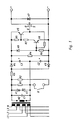
- an AC voltage induced by the fault current in the secondary winding N2 is limited by the Z-diode chain V1 / V2 and via the charging resistor R3 that consisting of the diodes V3 / V4 and the capacitors C2 / C3 , voltage doubling rectifier supplied.
- the resistor R4 represents a basic load for the direct voltage obtained in this way.
- the positive feedback via the PNP transistor V5 causes not only clear switching states and steep switching edges, but also a switching hysteresis.
- the NPN transistor V6 is initially kept conductive via the conductive transistor V5 and the voltage divider R8 / R6. Only when the response fault current is significantly undershot does the voltage drop at R6 drop below approx. 0.5 volts, causing V6 and thus also V5 to switch to the blocked state. The positive feedback is thus eliminated, the switching stage suddenly tilts back to the "OFF" state.
- the MOS transistor V9 acting as an output contact according to FIG. 1 is controlled directly by this switching stage.
- the Zener diode V7 protects the MOS transistor V9 against too high voltages and against voltages of wrong polarity.
- a bridge rectifier can be connected downstream to switch AC voltages.
- a self-conducting MOS depletion transistor V10 can be used as an output contact. This enables quiescent current outputs to be implemented.
- the resistor R1 is used for the basic setting of the response values for AC and pulsating DC fault currents.
- the Message from the sensor with a time delay that depends on the level of the flowing fault current.
- the delay characteristic can also be set by suitable dimensioning of the diodes V1 / V2, the charging resistor R3 and the capacitors C2 / C3.
- both sensor circuits offer the possibility of increasing the response threshold by inserting a short-circuit bridge X in each circuit. By closing the respective short-circuit bridge, a resistor R2 is switched on, which increases the response threshold.
Landscapes
- Engineering & Computer Science (AREA)
- Power Engineering (AREA)
- Protection Of Static Devices (AREA)
- Emergency Protection Circuit Devices (AREA)
- Electronic Switches (AREA)
- Hydraulic Clutches, Magnetic Clutches, Fluid Clutches, And Fluid Joints (AREA)
- Dc-Dc Converters (AREA)
Applications Claiming Priority (2)
| Application Number | Priority Date | Filing Date | Title |
|---|---|---|---|
| DE4039921 | 1990-12-14 | ||
| DE19904039921 DE4039921A1 (de) | 1990-12-14 | 1990-12-14 | Fehlerstrom-sensorschaltung |
Publications (2)
| Publication Number | Publication Date |
|---|---|
| EP0490123A2 true EP0490123A2 (fr) | 1992-06-17 |
| EP0490123A3 EP0490123A3 (en) | 1993-03-10 |
Family
ID=6420297
Family Applications (1)
| Application Number | Title | Priority Date | Filing Date |
|---|---|---|---|
| EP19910119623 Ceased EP0490123A3 (en) | 1990-12-14 | 1991-11-18 | Fault current sensor circuit |
Country Status (3)
| Country | Link |
|---|---|
| EP (1) | EP0490123A3 (fr) |
| DE (1) | DE4039921A1 (fr) |
| NO (1) | NO914532L (fr) |
Cited By (2)
| Publication number | Priority date | Publication date | Assignee | Title |
|---|---|---|---|---|
| EP0590435B1 (fr) * | 1992-10-01 | 1997-02-19 | Siemens Aktiengesellschaft | Dispositif d'acquisition de courant de défaut, répondant à tout courant avec acquisition de courant de défaut alternatif ou pulsatoire, indifférents aux courants de défaut continus |
| EP1046920A3 (fr) * | 1999-04-20 | 2004-01-28 | Alcatel | Circuit pour la détection de seuils de courant |
Families Citing this family (4)
| Publication number | Priority date | Publication date | Assignee | Title |
|---|---|---|---|---|
| DE19526435B4 (de) * | 1995-06-01 | 2004-07-22 | Continental Teves Ag & Co. Ohg | Schaltungsanordnung zur Fehlerstromerkennung |
| DE19735743A1 (de) | 1997-08-18 | 1999-02-25 | Siemens Ag | Fehlerstrom-Schutzeinrichtung |
| DE102019117103A1 (de) | 2019-06-25 | 2020-12-31 | Doepke Schaltgeräte GmbH | Vorrichtung zur Erfassung von Differenzströmen in gleichstromgespeisten elektrischen Anlagen |
| DE102020102689A1 (de) | 2020-02-04 | 2021-08-05 | Doepke Schaltgeräte GmbH | Schutzschalteinrichtung |
Family Cites Families (7)
| Publication number | Priority date | Publication date | Assignee | Title |
|---|---|---|---|---|
| US3737726A (en) * | 1972-03-28 | 1973-06-05 | Heinemann Electric Ltd | Earth leakage detector for operating circuit interrupting means |
| US4034267A (en) * | 1975-12-12 | 1977-07-05 | Westinghouse Electric Corporation | Indicating apparatus |
| DE2855228A1 (de) * | 1978-12-21 | 1980-07-03 | Insta Elektro Gmbh & Co Kg | Schaltungsanordnung fuer ein netzausfallmeldegeraet |
| DE2856316C3 (de) * | 1978-12-27 | 1983-11-03 | Felten & Guilleaume Energietechnik GmbH, 5000 Köln | Elektronisches Auslösesystem für Schutzschalter, insbesondere für Fehlerstrom-Schutzschalter |
| DE3014644A1 (de) * | 1980-04-16 | 1981-10-22 | S. Siedle & Söhne Telefon- und Telegrafenwerke GmbH, 7743 Furtwangen | Netzgeraet |
| DE3543948A1 (de) * | 1985-12-12 | 1987-06-19 | Siemens Ag | Anordnung zum erfassen von fehlerstroemen |
| DE3543985A1 (de) * | 1985-12-12 | 1987-06-19 | Siemens Ag | Anordnung zum erfassen von fehlerstroemen |
-
1990
- 1990-12-14 DE DE19904039921 patent/DE4039921A1/de not_active Withdrawn
-
1991
- 1991-11-18 EP EP19910119623 patent/EP0490123A3/de not_active Ceased
- 1991-11-20 NO NO91914532A patent/NO914532L/no unknown
Cited By (2)
| Publication number | Priority date | Publication date | Assignee | Title |
|---|---|---|---|---|
| EP0590435B1 (fr) * | 1992-10-01 | 1997-02-19 | Siemens Aktiengesellschaft | Dispositif d'acquisition de courant de défaut, répondant à tout courant avec acquisition de courant de défaut alternatif ou pulsatoire, indifférents aux courants de défaut continus |
| EP1046920A3 (fr) * | 1999-04-20 | 2004-01-28 | Alcatel | Circuit pour la détection de seuils de courant |
Also Published As
| Publication number | Publication date |
|---|---|
| EP0490123A3 (en) | 1993-03-10 |
| DE4039921A1 (de) | 1992-06-17 |
| NO914532D0 (no) | 1991-11-20 |
| NO914532L (no) | 1992-06-15 |
Similar Documents
| Publication | Publication Date | Title |
|---|---|---|
| DE2638178C2 (de) | Schutzvorrichtung für integrierte Schaltungen gegen Überspannungen | |
| WO1997036373A1 (fr) | Appareil de commutation electronique de derivation | |
| EP0208065A2 (fr) | Disposition de circuit pour enclencher des transistors de puissance haute tension | |
| EP0490123A2 (fr) | Circuit de détection de courant de défaut | |
| EP0183108A1 (fr) | Dispositif de surveillance de court-circuit pour moteurs à courant triphasé régularisés en vitesse ainsi que de leurs câbles d'alimentation | |
| CH625917A5 (fr) | ||
| EP0339598A2 (fr) | Circuit de protection pour charges inductives | |
| DE1911202B2 (de) | Elektronische ueberstromausloesung fuer elektrische schalter | |
| DE3885703T2 (de) | Zusatzmodul zur erdschlussermittlung. | |
| EP0160235B1 (fr) | Dispositif de surveillance pour le circuit de déclenchement d'un interrupteur à puissance et procédé de surveillance | |
| DE3828428C1 (en) | Voltage supply for proximity switches | |
| DE3738493A1 (de) | Fehlerortungseinrichtung | |
| DE2624252B2 (de) | Überlastschutz-Schaltung für eine Lautsprecheranordnung | |
| DE3407311A1 (de) | Schaltungsanordnung zur ueberwachung einer spannung | |
| DE715476C (de) | Schaltung fuer langsam arbeitende Relaisselbstunterbrecher | |
| DE2635763A1 (de) | Brandmeldeanlage mit mehreren ueber eine meldeschleife betreibbaren meldern | |
| DE1092967B (de) | Schaltungsanordnung fuer einen kurzschlussfesten Wechselspannungsgenerator | |
| DE1763618A1 (de) | Fehlerdetektor fuer Doppelleitung oder zweiadriges Kabel | |
| DE1588405B1 (de) | Stromversorgungseinrichtung zum Aufladen einer Kraftfahrzeugbatterie | |
| AT207899B (de) | Elektrische Schaltungsanordnung zur Lieferung einer Ausgangsspannung in Abhängigkeit von einer bestimmten Eingangsspannung, vorzugsweise für Fernmeldeanlagen | |
| DE1956733C3 (de) | Schaltungsanordnung zur Spannungsbegrenzung an Schalttransistoren beim Abschalten von Gleichstromkreisen mit einer Induktivität | |
| DE1933942C (de) | Anordnung zur elektronischen Über wachung der Sicherungselemente von paral lelgeschalteten Verbraucherstromkreisen | |
| DE426299C (de) | Selbsttaetige Wiedereinschaltvorrichtung fuer selbsttaetige Schalter | |
| DE1064123B (de) | Fuer zwei stark unterschiedliche Netzspannungen bestimmtes elektrisches Geraet | |
| DE1172754B (de) | Steuergeraet fuer Synchronschalter |
Legal Events
| Date | Code | Title | Description |
|---|---|---|---|
| PUAI | Public reference made under article 153(3) epc to a published international application that has entered the european phase |
Free format text: ORIGINAL CODE: 0009012 |
|
| AK | Designated contracting states |
Kind code of ref document: A2 Designated state(s): AT BE DE DK ES FR IT NL SE |
|
| PUAL | Search report despatched |
Free format text: ORIGINAL CODE: 0009013 |
|
| AK | Designated contracting states |
Kind code of ref document: A3 Designated state(s): AT BE DE DK ES FR IT NL SE |
|
| 17P | Request for examination filed |
Effective date: 19930805 |
|
| 17Q | First examination report despatched |
Effective date: 19940203 |
|
| STAA | Information on the status of an ep patent application or granted ep patent |
Free format text: STATUS: THE APPLICATION HAS BEEN REFUSED |
|
| 18R | Application refused |
Effective date: 19940714 |