EP0490133A2 - Manchon pour zone de dérivation ou de jonction de câbles - Google Patents
Manchon pour zone de dérivation ou de jonction de câbles Download PDFInfo
- Publication number
- EP0490133A2 EP0490133A2 EP91119811A EP91119811A EP0490133A2 EP 0490133 A2 EP0490133 A2 EP 0490133A2 EP 91119811 A EP91119811 A EP 91119811A EP 91119811 A EP91119811 A EP 91119811A EP 0490133 A2 EP0490133 A2 EP 0490133A2
- Authority
- EP
- European Patent Office
- Prior art keywords
- sleeve
- cables
- molded part
- cable
- branch
- Prior art date
- Legal status (The legal status is an assumption and is not a legal conclusion. Google has not performed a legal analysis and makes no representation as to the accuracy of the status listed.)
- Granted
Links
Images

Classifications
-
- H—ELECTRICITY
- H02—GENERATION; CONVERSION OR DISTRIBUTION OF ELECTRIC POWER
- H02G—INSTALLATION OF ELECTRIC CABLES OR LINES, OR OF COMBINED OPTICAL AND ELECTRIC CABLES OR LINES
- H02G15/00—Cable fittings
- H02G15/08—Cable junctions
- H02G15/10—Cable junctions protected by boxes, e.g. by distribution, connection or junction boxes
- H02G15/117—Cable junctions protected by boxes, e.g. by distribution, connection or junction boxes for multiconductor cables
-
- G—PHYSICS
- G02—OPTICS
- G02B—OPTICAL ELEMENTS, SYSTEMS OR APPARATUS
- G02B6/00—Light guides; Structural details of arrangements comprising light guides and other optical elements, e.g. couplings
- G02B6/44—Mechanical structures for providing tensile strength and external protection for fibres, e.g. optical transmission cables
- G02B6/4439—Auxiliary devices
- G02B6/444—Systems or boxes with surplus lengths
-
- H—ELECTRICITY
- H02—GENERATION; CONVERSION OR DISTRIBUTION OF ELECTRIC POWER
- H02G—INSTALLATION OF ELECTRIC CABLES OR LINES, OR OF COMBINED OPTICAL AND ELECTRIC CABLES OR LINES
- H02G15/00—Cable fittings
- H02G15/013—Sealing means for cable inlets
Definitions
- the invention relates to a sleeve for a branch or connection point of cables, in particular communication cables with optical fibers, consisting of a sleeve surrounding the branch point or connection point, which is connected at the end in a liquid-tight manner to one end body penetrating into the sleeve, each of which has at least one Has passage opening for inserting a cable into the sleeve or for leading the cable out of the sleeve.
- Such a sleeve is known from DE-OS 38 17 795.
- the sleeve and the front body each consist of two half-shells.
- Each end body has a central bore through which the main cable enters and exits and a through opening arranged at a radial distance therefrom through which the branching cable passes.
- the half-shells are glued together for the purpose of sealing. Both the central passage opening and the second passage opening are sealed off from the respective cable by a shrink tube.
- the annular gap between the sleeve and the end body penetrating into it is sealed by a tensioning element.
- this sleeve is that after releasing the tensioning elements, the sleeve can be moved over one of the end bodies, making the interior of the sleeve accessible. New cables can be connected by not going through them yet occupied openings are introduced. The sleeve can then be moved back to its original position and the clamping elements can be actuated again.
- a disadvantage of this sleeve is that it is difficult to keep the seams between the half-shell permanently tight. Because of the considerable forces that have to be applied by the tensioning elements for a good seal, the seal can be damaged at the seams. Water can then penetrate and the sleeve and possibly make the cable unusable.
- the present invention is therefore based on the object of improving the known sleeve in such a way that a secure seal against the ingress of moisture is achieved while maintaining the advantageous properties.
- manufacture of the sleeve i.e. the arrangement of the cables is simplified, in particular the subsequent arrangement of branch cables is to be improved.
- the sleeve should be usable equally with cut as well as with uncut cables.
- the sleeve according to the teaching of the invention is very stable and easy to assemble through the sleeve and the front body.
- the relatively rigid plastic such as Polyethylene
- existing sleeve has a good resilience and easily reforms into a tube with a narrow slot.
- the heat-shrunk sleeve provides an absolutely secure seal against the ingress of moisture.
- the sleeve is easy to reopen and can accordingly be used for the subsequent setting of another branch.
- the entry area is bonded and sealed by means of a hot-melt adhesive, which is located on the inner surface of the sleeve and the surface of the molded part and becomes liquid at the shrinking temperature and runs. Between the cables, the cuff is removed using a tool, e.g. a pair of pliers, clamps etc. held together during the shrinking process. After cooling, the hot melt adhesive has solidified and holds the area between the cables together.
- the molded part is particularly advantageously designed such that a plurality of blind holes are made in the outwardly facing end face of the molded part, into which at least one part defining the sleeve between itself and the molded part surface, such as a clamp, spring, pin, etc., is inserted.
- the clamps, springs or pins essentially serve to bring the sleeve into contact with most of the surface of the cable.
- the molded part can be designed in almost any way. However, it has proven to be advantageous for the molded part to be designed as a cylindrical part and for the cables that exit or enter to rest on the peripheral surface of the molded part.
- the molded part can be solid or as a cup.
- the molded part essentially has the task of making the relatively large jump in diameter between the sleeve and e.g. to bridge an optical fiber cable, and to make sealing possible by means of the heat-shrinking sleeve.
- the molded part can be made of plastic or another material. However, it has proven to be advantageous to use the molded part made of metal, e.g. To produce aluminum or an aluminum alloy or from metal-coated plastic. In this way, the heat applied during the shrinking heat is transported into the interior of the casing formed by the sleeve, whereby a particularly secure and simple seal is achieved. If the molded part and the end body are formed in one piece, a stable design of the end regions of the sleeve is obtained. On the end bodies, namely on their inwardly facing surface, there are pegs to which the cables are attached.
- openings can be provided on the molded part, through which a tension band is passed and which is placed around the cables.
- the end bodies are held in a particularly expedient manner at a distance from one another and connected to one another by means of at least one rail. This is advantageous because it means the distance between the forehead bodies is fixed, whereby the laying around of the sleeve leads to an exact contact of the ends of the sleeve with the flanges of the end bodies.
- This rail is also used to attach cassettes for the optical fiber splice.
- both the longitudinal slot of the sleeve and the circumferential gap between the sleeve and the end body are covered, e.g. with an adhesive strip to prevent hot melt adhesive from entering the gaps.
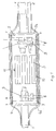
- FIG. 1 shows a side view of the partially cut sleeve.
- the cable entering the sleeve is denoted by 1, from which a branch cable 2 branches.
- Both the cable 1 and the branch cable 2 are intended to be optical waveguide cables in the exemplary embodiment, although the invention can also be used for electrical cables.
- the connections of the optical fibers of the cables 1 and 2, not shown in more detail, are located in a so-called splice cassette 3, which is arranged within the sleeve.
- the sleeve consists of two end bodies 4 and 5, on the circumferential surface of which a longitudinally slotted plastic tube 6 rests. A flange 4a or 5a protrudes from the peripheral surface of the end bodies 4 and 5, on which the slotted plastic tube 6 is supported with its ends.
- the front bodies 4 and 5 have radial slots for inserting the cables 1 and 2.
- pins 8 are provided which mechanically with the support bodies 4 and 5 are firmly connected, advantageously part of these, to which the cables 1 and 2 are fastened with clamps 9 for the purpose of strain relief of the connection point.
- the end bodies 4 and 5 are connected to a rail 10 which is embedded in the peripheral surface and is screwed there as shown at 7.
- the rail 10 defines the distance between the end bodies 4 and 5 and ensures that the slotted plastic tube 6 bears against the flanges 4a and 5a.
- the outer end of the sleeve is formed by a heat-shrunk sleeve 11, which consists of a band made of cross-linked plastic, the longitudinal edges of which are held together by a flexible rail, not shown.
- the length of the sleeve 11 is dimensioned such that it covers the plastic tube 6 and the end bodies 4 and 5 and is shrunk onto the incoming and outgoing cables 1 and 2.
- the longitudinal slot of the plastic tube 6 and the circumferential gaps between the plastic tube 6 and the end bodies 4 and 5 are covered with an adhesive tape in a manner not shown.
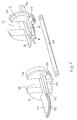
- FIG. 2 shows the two end bodies 4 and 5 before they are assembled.
- the front bodies 4 and 5 have a plurality of radial slots 12 to 15, into which the cables 1 and 2 or further cables are inserted.
- a molded part 16 protrudes from the outwardly facing surface of the end bodies 4 and 5, which is expediently part of the end body 4 and 5, respectively.
- Blind holes 17 are made in the end face of the molded part 16. These blind bores 17 serve, as described later, to seal the socket end.
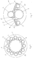
- Figures 3 to 5 show views of different end bodies 4 and 5.
- the front body 4 and 5 of Figure 3 has a plurality of radial slots 18 for receiving a plurality of relatively thin branch cables.
- the molded part 16 is cylindrical. There are a number of blind holes on its outer periphery.
- the end bodies 4 and 5 have two large radial slots 20 and four small radial slots 19.
- the molded part 16 is cuboid and shows the blind holes on its end face.
- Figures 6 and 7 show views of the sealed end portion of the sleeve.
- a plurality of relatively thin branch cables 2 emerge from the sleeve according to FIG.
- the front body 4 is similar to that shown in Figure 3 and has a cylindrical shape.
- the sleeve 11 is formed around the branch cable 2 by means of the plug-in elements 21 before shrinking. As in the earlier patent application P 40 29 515.8, the plug elements 21 are inserted into the blind holes 17.
- One arm of the plug element 21 lies on the outer surface of the sleeve 11.
- the gussets 22 located between the sleeve 11 and the branch cables 2 are filled and sealed during the shrinking process by the hot-melt adhesive provided on the surface of the sleeve 11.
- FIG. 7 shows a further embodiment of the invention.
- the branch cables 2 branched off from the cable 1 lie like the cable 1 on the molded part 16, which is slightly curved and essentially shows the shape of a cuboid.
- a branch cable 2 is also arranged on the side opposite the cable 1.
- the main advantage achieved by the invention is to be seen in the fact that the cuff can completely seal the end region through the molded part, which would be impossible because of the large diameter difference between the cable and the sleeve, since degrees of stretching of more than 400% are hardly possible.
- the diameter of the sleeve in optical fiber cables can be up to 100 mm because of the fiber supply to be provided and its winding diameter, while the cable diameter is of the order of 10 mm.
Landscapes
- Physics & Mathematics (AREA)
- General Physics & Mathematics (AREA)
- Optics & Photonics (AREA)
- Cable Accessories (AREA)
- Mechanical Coupling Of Light Guides (AREA)
- Insulated Conductors (AREA)
- Connections Effected By Soldering, Adhesion, Or Permanent Deformation (AREA)
- Insulating Bodies (AREA)
Applications Claiming Priority (2)
| Application Number | Priority Date | Filing Date | Title |
|---|---|---|---|
| DE4039242 | 1990-12-08 | ||
| DE4039242A DE4039242A1 (de) | 1990-12-08 | 1990-12-08 | Muffe fuer eine abzweig- oder verbindungsstelle von kabeln |
Publications (3)
| Publication Number | Publication Date |
|---|---|
| EP0490133A2 true EP0490133A2 (fr) | 1992-06-17 |
| EP0490133A3 EP0490133A3 (en) | 1993-03-24 |
| EP0490133B1 EP0490133B1 (fr) | 1994-08-31 |
Family
ID=6419901
Family Applications (1)
| Application Number | Title | Priority Date | Filing Date |
|---|---|---|---|
| EP91119811A Expired - Lifetime EP0490133B1 (fr) | 1990-12-08 | 1991-11-21 | Manchon pour zone de dérivation ou de jonction de câbles |
Country Status (8)
| Country | Link |
|---|---|
| US (1) | US5204933A (fr) |
| EP (1) | EP0490133B1 (fr) |
| JP (1) | JPH04274403A (fr) |
| AT (1) | ATE110894T1 (fr) |
| CA (1) | CA2057119A1 (fr) |
| DE (2) | DE4039242A1 (fr) |
| DK (1) | DK0490133T3 (fr) |
| ES (1) | ES2064861T3 (fr) |
Cited By (2)
| Publication number | Priority date | Publication date | Assignee | Title |
|---|---|---|---|---|
| EP0650239A1 (fr) * | 1993-10-22 | 1995-04-26 | Kabelmetal Electro GmbH | Manchon recevant des emplacements de dérivations ou de jonctions de câbles à fibres optiques ou de câbles électriques |
| US5753861A (en) * | 1995-02-10 | 1998-05-19 | Minnesota Mining And Manufacturing | Covering device |
Families Citing this family (5)
| Publication number | Priority date | Publication date | Assignee | Title |
|---|---|---|---|---|
| DE59813727D1 (de) * | 1997-02-14 | 2006-11-02 | Nexans Deutschland Ind Ag & Co | Anordnung zur Abzweigung an einem mehrere Verseilelemente mit optischen Fasern enthaltenden Fernmeldekabel |
| GB2343261B (en) * | 1998-10-29 | 2002-12-11 | Bowthorpe Plc | Optical fibre storage apparatus with movable stacks |
| GB2452780B (en) * | 2007-09-17 | 2012-05-30 | David Frederick Hawkins | A cable duct restraining device |
| US9240261B2 (en) * | 2013-07-19 | 2016-01-19 | Alcatel-Lucent Shanghai Bell Co., Ltd | Multi-conductor cables with spacers for conductors |
| GB2585377B (en) * | 2019-07-05 | 2023-09-06 | British Telecomm | Protective Apparatus |
Family Cites Families (8)
| Publication number | Priority date | Publication date | Assignee | Title |
|---|---|---|---|---|
| US3455336A (en) * | 1965-11-03 | 1969-07-15 | Raychem Corp | Heat recoverable article and process |
| DE2263419A1 (de) * | 1972-12-27 | 1974-07-11 | Siemens Ag | Kabelgarnitur |
| DE2343764A1 (de) * | 1973-08-28 | 1975-03-06 | Siemens Ag | Kabelgarnitur, insbesondere muffen fuer nachrichtenkabel, mit einem laengsgeteilten gehaeuse |
| GB2095926B (en) * | 1979-01-09 | 1983-03-09 | Raychem Sa Nv | Branch-off method |
| DE3817795A1 (de) * | 1987-12-22 | 1989-12-07 | Kabelmetal Electro Gmbh | Muffe fuer eine abzweig- oder verbindungsstelle von kabeln |
| US4891640A (en) * | 1988-11-03 | 1990-01-02 | Halliburton Logging Services, Inc. | High temperature and pressure fiber optic feedthrough for borehole usage |
| US5119457A (en) * | 1990-08-15 | 1992-06-02 | University Research Engineers & Associates, Inc. | High-performance electric power cable and connector system |
| US5099399A (en) * | 1991-04-08 | 1992-03-24 | Miller Jack V | High efficiency fiber optics illuminator with thermally controlled light guide bushing |
-
1990
- 1990-12-08 DE DE4039242A patent/DE4039242A1/de not_active Withdrawn
-
1991
- 1991-11-21 DE DE59102736T patent/DE59102736D1/de not_active Expired - Fee Related
- 1991-11-21 EP EP91119811A patent/EP0490133B1/fr not_active Expired - Lifetime
- 1991-11-21 DK DK91119811.7T patent/DK0490133T3/da active
- 1991-11-21 ES ES91119811T patent/ES2064861T3/es not_active Expired - Lifetime
- 1991-11-21 AT AT91119811T patent/ATE110894T1/de active
- 1991-12-04 US US07/802,209 patent/US5204933A/en not_active Expired - Fee Related
- 1991-12-05 CA CA002057119A patent/CA2057119A1/fr not_active Abandoned
- 1991-12-06 JP JP3323407A patent/JPH04274403A/ja active Pending
Cited By (2)
| Publication number | Priority date | Publication date | Assignee | Title |
|---|---|---|---|---|
| EP0650239A1 (fr) * | 1993-10-22 | 1995-04-26 | Kabelmetal Electro GmbH | Manchon recevant des emplacements de dérivations ou de jonctions de câbles à fibres optiques ou de câbles électriques |
| US5753861A (en) * | 1995-02-10 | 1998-05-19 | Minnesota Mining And Manufacturing | Covering device |
Also Published As
| Publication number | Publication date |
|---|---|
| ES2064861T3 (es) | 1995-02-01 |
| ATE110894T1 (de) | 1994-09-15 |
| DE4039242A1 (de) | 1992-06-11 |
| EP0490133B1 (fr) | 1994-08-31 |
| DE59102736D1 (de) | 1994-10-06 |
| CA2057119A1 (fr) | 1992-06-09 |
| JPH04274403A (ja) | 1992-09-30 |
| EP0490133A3 (en) | 1993-03-24 |
| DK0490133T3 (da) | 1995-01-30 |
| US5204933A (en) | 1993-04-20 |
Similar Documents
| Publication | Publication Date | Title |
|---|---|---|
| EP0522387B1 (fr) | Dispositif pour rendre étanche la partie terminale d'une manchette thermorétractable | |
| DE69010530T2 (de) | Verbinden von faseroptischen Kabeln. | |
| EP0650239A1 (fr) | Manchon recevant des emplacements de dérivations ou de jonctions de câbles à fibres optiques ou de câbles électriques | |
| DE9211419U1 (de) | Lichtleitfaser-Spleißvorrichtung | |
| DE2512330A1 (de) | Verbindungsglied fuer optische fasern | |
| DE69223518T2 (de) | Mehrfacher-spleiss für optische fasern | |
| DE2413623B2 (de) | Flüssigkeitsdichte, eingangsseitige Abdichtung von mindestens zwei in ein Muffengehäuse parallel einmündenden Kabeln | |
| DE60219183T2 (de) | Verfahren und vorrichtung zum spleissen von glasfasern | |
| DE69503195T2 (de) | Dichter Durchgang für Fernmeldekabel | |
| EP0537487B1 (fr) | Dispositif pour rendre étanche la partie terminale d'une manchette thermorétractable | |
| EP0490133B1 (fr) | Manchon pour zone de dérivation ou de jonction de câbles | |
| DE3736792C2 (de) | Verfahren zum Herstellen eines Endanschlusses eines faseroptischen Kabels | |
| DE69014859T2 (de) | Spleissverschlüsse. | |
| EP0051109A1 (fr) | Dispositif pour connecter et pour envelopper des connexions de câbles, notamment de câbles de communication à large bande | |
| EP0309677B1 (fr) | Elément de connexion pour guides d'ondes lumineuses | |
| DE69933954T2 (de) | Verbindungsdose für ein Kabel, insbesondere für ein faseroptisches Kabel | |
| DE2718027A1 (de) | Verbinder fuer lichtleitkabel | |
| EP0532980B1 (fr) | Manchon à chapeau pour la réception de jonctions de câbles | |
| EP0268180A2 (fr) | Dispositif pour fixer les câbles à fibres optiques dans une boîte de fiches | |
| DE4406154A1 (de) | Aufnahme mit Knickschutz für einen Faserspleiß | |
| DE4240170C2 (de) | Spleißgehäuse für ein Starkstromkabel mit integrierten Lichtwellenleitern | |
| DE3824648C2 (fr) | ||
| DE3301723C2 (fr) | ||
| DE69115467T2 (de) | Verfahren zum einschliessen eines substrates | |
| DE4006799A1 (de) | Verfahren zur herstellung einer schweissverbindungsstelle zwischen zwei gruppen von lichtwellenleitern und vorrichtung zur ausuebung des verfahrens |
Legal Events
| Date | Code | Title | Description |
|---|---|---|---|
| PUAI | Public reference made under article 153(3) epc to a published international application that has entered the european phase |
Free format text: ORIGINAL CODE: 0009012 |
|
| AK | Designated contracting states |
Kind code of ref document: A2 Designated state(s): AT BE CH DE DK ES FR GB GR IT LI NL SE |
|
| PUAL | Search report despatched |
Free format text: ORIGINAL CODE: 0009013 |
|
| AK | Designated contracting states |
Kind code of ref document: A3 Designated state(s): AT BE CH DE DK ES FR GB GR IT LI NL SE |
|
| 17P | Request for examination filed |
Effective date: 19930302 |
|
| 17Q | First examination report despatched |
Effective date: 19940204 |
|
| GRAA | (expected) grant |
Free format text: ORIGINAL CODE: 0009210 |
|
| AK | Designated contracting states |
Kind code of ref document: B1 Designated state(s): AT BE CH DE DK ES FR GB GR IT LI NL SE |
|
| REF | Corresponds to: |
Ref document number: 110894 Country of ref document: AT Date of ref document: 19940915 Kind code of ref document: T |
|
| ITF | It: translation for a ep patent filed | ||
| REF | Corresponds to: |
Ref document number: 59102736 Country of ref document: DE Date of ref document: 19941006 |
|
| GBT | Gb: translation of ep patent filed (gb section 77(6)(a)/1977) |
Effective date: 19940926 |
|
| ET | Fr: translation filed | ||
| REG | Reference to a national code |
Ref country code: GR Ref legal event code: FG4A Free format text: 3013600 |
|
| REG | Reference to a national code |
Ref country code: DK Ref legal event code: T3 |
|
| EAL | Se: european patent in force in sweden |
Ref document number: 91119811.7 |
|
| REG | Reference to a national code |
Ref country code: ES Ref legal event code: FG2A Ref document number: 2064861 Country of ref document: ES Kind code of ref document: T3 |
|
| PLBE | No opposition filed within time limit |
Free format text: ORIGINAL CODE: 0009261 |
|
| STAA | Information on the status of an ep patent application or granted ep patent |
Free format text: STATUS: NO OPPOSITION FILED WITHIN TIME LIMIT |
|
| 26N | No opposition filed | ||
| PGFP | Annual fee paid to national office [announced via postgrant information from national office to epo] |
Ref country code: SE Payment date: 19951114 Year of fee payment: 5 Ref country code: DK Payment date: 19951114 Year of fee payment: 5 Ref country code: AT Payment date: 19951114 Year of fee payment: 5 |
|
| PGFP | Annual fee paid to national office [announced via postgrant information from national office to epo] |
Ref country code: ES Payment date: 19951115 Year of fee payment: 5 |
|
| PGFP | Annual fee paid to national office [announced via postgrant information from national office to epo] |
Ref country code: NL Payment date: 19951123 Year of fee payment: 5 |
|
| PG25 | Lapsed in a contracting state [announced via postgrant information from national office to epo] |
Ref country code: DK Effective date: 19961121 Ref country code: AT Effective date: 19961121 |
|
| REG | Reference to a national code |
Ref country code: DK Ref legal event code: EBP |
|
| PG25 | Lapsed in a contracting state [announced via postgrant information from national office to epo] |
Ref country code: SE Effective date: 19961122 Ref country code: ES Free format text: LAPSE BECAUSE OF NON-PAYMENT OF DUE FEES Effective date: 19961122 |
|
| PG25 | Lapsed in a contracting state [announced via postgrant information from national office to epo] |
Ref country code: NL Effective date: 19970601 |
|
| NLV4 | Nl: lapsed or anulled due to non-payment of the annual fee |
Effective date: 19970601 |
|
| EUG | Se: european patent has lapsed |
Ref document number: 91119811.7 |
|
| PGFP | Annual fee paid to national office [announced via postgrant information from national office to epo] |
Ref country code: GB Payment date: 19981012 Year of fee payment: 8 Ref country code: FR Payment date: 19981012 Year of fee payment: 8 |
|
| PGFP | Annual fee paid to national office [announced via postgrant information from national office to epo] |
Ref country code: DE Payment date: 19981022 Year of fee payment: 8 |
|
| PGFP | Annual fee paid to national office [announced via postgrant information from national office to epo] |
Ref country code: CH Payment date: 19981023 Year of fee payment: 8 |
|
| PGFP | Annual fee paid to national office [announced via postgrant information from national office to epo] |
Ref country code: BE Payment date: 19981030 Year of fee payment: 8 |
|
| PGFP | Annual fee paid to national office [announced via postgrant information from national office to epo] |
Ref country code: GR Payment date: 19981130 Year of fee payment: 8 |
|
| PG25 | Lapsed in a contracting state [announced via postgrant information from national office to epo] |
Ref country code: GB Free format text: LAPSE BECAUSE OF NON-PAYMENT OF DUE FEES Effective date: 19991121 |
|
| PG25 | Lapsed in a contracting state [announced via postgrant information from national office to epo] |
Ref country code: LI Free format text: LAPSE BECAUSE OF NON-PAYMENT OF DUE FEES Effective date: 19991130 Ref country code: GR Free format text: LAPSE BECAUSE OF NON-PAYMENT OF DUE FEES Effective date: 19991130 Ref country code: CH Free format text: LAPSE BECAUSE OF NON-PAYMENT OF DUE FEES Effective date: 19991130 Ref country code: BE Free format text: LAPSE BECAUSE OF NON-PAYMENT OF DUE FEES Effective date: 19991130 |
|
| BERE | Be: lapsed |
Owner name: KABELMETAL ELECTRO G.M.B.H. Effective date: 19991130 |
|
| GBPC | Gb: european patent ceased through non-payment of renewal fee |
Effective date: 19991121 |
|
| REG | Reference to a national code |
Ref country code: CH Ref legal event code: PL |
|
| PG25 | Lapsed in a contracting state [announced via postgrant information from national office to epo] |
Ref country code: FR Free format text: LAPSE BECAUSE OF NON-PAYMENT OF DUE FEES Effective date: 20000731 |
|
| PG25 | Lapsed in a contracting state [announced via postgrant information from national office to epo] |
Ref country code: DE Free format text: LAPSE BECAUSE OF NON-PAYMENT OF DUE FEES Effective date: 20000901 |
|
| REG | Reference to a national code |
Ref country code: FR Ref legal event code: ST |
|
| REG | Reference to a national code |
Ref country code: ES Ref legal event code: FD2A Effective date: 19971213 |
|
| PG25 | Lapsed in a contracting state [announced via postgrant information from national office to epo] |
Ref country code: IT Free format text: LAPSE BECAUSE OF NON-PAYMENT OF DUE FEES;WARNING: LAPSES OF ITALIAN PATENTS WITH EFFECTIVE DATE BEFORE 2007 MAY HAVE OCCURRED AT ANY TIME BEFORE 2007. THE CORRECT EFFECTIVE DATE MAY BE DIFFERENT FROM THE ONE RECORDED. Effective date: 20051121 |