EP0490194A1 - Ecrou avec filetage autobloquant - Google Patents
Ecrou avec filetage autobloquant Download PDFInfo
- Publication number
- EP0490194A1 EP0490194A1 EP91120567A EP91120567A EP0490194A1 EP 0490194 A1 EP0490194 A1 EP 0490194A1 EP 91120567 A EP91120567 A EP 91120567A EP 91120567 A EP91120567 A EP 91120567A EP 0490194 A1 EP0490194 A1 EP 0490194A1
- Authority
- EP
- European Patent Office
- Prior art keywords
- thread
- screw
- offset
- axially offset
- rolling jaw
- Prior art date
- Legal status (The legal status is an assumption and is not a legal conclusion. Google has not performed a legal analysis and makes no representation as to the accuracy of the status listed.)
- Withdrawn
Links
- 238000005096 rolling process Methods 0.000 claims description 20
- 238000004519 manufacturing process Methods 0.000 claims description 5
- 238000000034 method Methods 0.000 claims description 3
- 230000015572 biosynthetic process Effects 0.000 description 1
- 230000005764 inhibitory process Effects 0.000 description 1
- 230000002093 peripheral effect Effects 0.000 description 1
- 230000036316 preload Effects 0.000 description 1
- 230000007704 transition Effects 0.000 description 1
Images

Classifications
-
- F—MECHANICAL ENGINEERING; LIGHTING; HEATING; WEAPONS; BLASTING
- F16—ENGINEERING ELEMENTS AND UNITS; GENERAL MEASURES FOR PRODUCING AND MAINTAINING EFFECTIVE FUNCTIONING OF MACHINES OR INSTALLATIONS; THERMAL INSULATION IN GENERAL
- F16B—DEVICES FOR FASTENING OR SECURING CONSTRUCTIONAL ELEMENTS OR MACHINE PARTS TOGETHER, e.g. NAILS, BOLTS, CIRCLIPS, CLAMPS, CLIPS OR WEDGES; JOINTS OR JOINTING
- F16B39/00—Locking of screws, bolts or nuts
- F16B39/22—Locking of screws, bolts or nuts in which the locking takes place during screwing down or tightening
- F16B39/28—Locking of screws, bolts or nuts in which the locking takes place during screwing down or tightening by special members on, or shape of, the nut or bolt
- F16B39/30—Locking exclusively by special shape of the screw-thread
-
- B—PERFORMING OPERATIONS; TRANSPORTING
- B21—MECHANICAL METAL-WORKING WITHOUT ESSENTIALLY REMOVING MATERIAL; PUNCHING METAL
- B21H—MAKING PARTICULAR METAL OBJECTS BY ROLLING, e.g. SCREWS, WHEELS, RINGS, BARRELS, BALLS
- B21H3/00—Making helical bodies or bodies having parts of helical shape
- B21H3/02—Making helical bodies or bodies having parts of helical shape external screw-threads ; Making dies for thread rolling
- B21H3/025—Rolling locking screws
Definitions
- Screws that are screwed into an existing nut thread can loosen, especially if vibrations act on the screw connection. This is the case, for example, with machine screws which are arranged on parts suffering from vibrations, for example in automobiles.
- the unwanted self-loosening is caused by a relative movement, since the thread cannot normally be made without play.
- Unintentional loosening of a screw is not only annoying, it is also often associated with dangers. There are therefore many constructive proposals to prevent screws from being loosened unintentionally.
- a group of securing means provides elements on the screw head or below the screw head in the upper region of the shaft, which create an inhibition between the head and / or shaft on the one hand and the workpiece on the other.
- the invention has for its object to provide a screw with a self-locking thread that is easy to manufacture and reliably prevents relative movement in a screw connection.
- the invention belongs to the last-mentioned category.
- the thread In at least one thread flank of the area in engagement with a nut thread, the thread extends over a limited circumferential length axially offset section.
- several thread flanks are provided with axially offset sections which can be offset from one another in the circumferential direction.
- the axially offset flank sections of a plurality of turns are preferably arranged in a row, preferably parallel to the screw axis.
- the safety region which has the axially offset flank sections preferably extends over the entire screw length. In the case of axially offset flank sections arranged in a row, these can have the same circumferential length over the circumference.
- the circumferential length of the axially offset flank sections can gradually increase from the screw tip to the screw head.
- the offset of the thread flank on the screw thread means that forming work is carried out, so that a thread free of play is generated and thus a relative movement in the screw connection is prevented. If a relative movement is no longer possible, the connection can no longer be unintentionally released.
- the axially offset flank section can be 1/4 to 1/5 of the Extend the circumference of the screw.
- such a thread is more difficult to manufacture.
- the axial offset of the thread flank must have a minimum so that the desired deformation work is achieved. On the other hand, it must not be too large, since otherwise the effort required to screw the screw into the nut thread will be too great. If the offset is too large, the tightening torque is impermissible, while the preload torque is reduced. According to one embodiment of the invention, the offset dimension is 15 to 50% of the thread pitch. An offset of more than 50% is inappropriate for the reasons mentioned.
- the screw according to the invention expediently has an otherwise fully profiled thread, the securing region having the offset flanks not causing a substantial change in the thread profile.
- the screw according to the invention can be used with conventional Rolling jaws are manufactured.
- a method according to the invention provides that first a thread rolling jaw with the shaped profile for the screw thread is produced without offset flank sections, with a locking section of the rolling jaw having the size of the offset portions being approximately displaced by the offset dimension approximately perpendicular to the thread flanks and then the screw thread is formed. With the offset section of the rolling jaw, the securing area is formed during thread rolling.
- the rolling jaw for carrying out the method has at least one insert which can be accommodated by a recess in the rolling jaw and which can be displaced approximately perpendicular to the thread flanks. Means can be provided for at least one-end fixing of the insert after being moved in the rolling jaw before the screw thread is formed.
- the shaft 10 has a thread 14, for example a conventional metric thread, which is also fully profiled in the shaft.
- the free end of the shaft 10 has a conical section 16.
- the area surrounded by the dash-dotted circle 2 is shown in perspective in FIG. 2. It can be seen that the flanks 18 of the thread 14 are deformed in a peripheral region, as can be seen at 20.
- the deformation 20 consists in an axial offset Pv of the flanks 18 by one certain amount, where Pv can be 15 to 50% of the pitch P of the thread 14. Between the transition sections 22, the axially offset sections 20 run like the flanks of the rest of the thread 14, only shifted by the mentioned axial offset.
- the extent of the sections 20 in the circumferential direction of the screw can be 1/4 to 1/5 of the circumference.
- the axially offset sections 20 can extend over the entire thread, as indicated in FIG. 1.
- a securing area which consists of a series of axially offset flank sections, are shown.
- all axially offset flank sections 20 are of the same length, and the securing area extends parallel to the screw axis.
- the row of flank sections also extends axially parallel, but the length gradually increases in the direction of the screw head 12 (wedge shape).
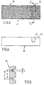
- a rolling jaw 30 is shown with which the thread 14 can be formed.
- the rolling jaw 30 is manufactured in the usual way. However, it has an insert 32 which can have a slightly wedge-shaped cross-section (FIG. 4) and which is received in a correspondingly shaped recess 34.
- the shaped thread of the rolling jaw 30 is produced in the usual way, the thread being simultaneously shaped in the insert 32 in the same way.
- the stake is then shifted by the amount Pv and preferably only fixed at one end (not shown).
- the thread 14 is then rolled, so that the thread 14 in the A design results in the rolling jaw 30.
- 3 shows the state of the rolling jaw 30 after the insert 32 has been displaced. This also results from the sectional view according to FIG. 5.
Landscapes
- Engineering & Computer Science (AREA)
- General Engineering & Computer Science (AREA)
- Mechanical Engineering (AREA)
- Forging (AREA)
- Transmission Devices (AREA)
Applications Claiming Priority (2)
| Application Number | Priority Date | Filing Date | Title |
|---|---|---|---|
| DE19904039402 DE4039402A1 (de) | 1990-12-10 | 1990-12-10 | Schraube mit selbstsicherndem gewinde |
| DE4039402 | 1990-12-10 |
Publications (1)
| Publication Number | Publication Date |
|---|---|
| EP0490194A1 true EP0490194A1 (fr) | 1992-06-17 |
Family
ID=6419997
Family Applications (1)
| Application Number | Title | Priority Date | Filing Date |
|---|---|---|---|
| EP91120567A Withdrawn EP0490194A1 (fr) | 1990-12-10 | 1991-11-29 | Ecrou avec filetage autobloquant |
Country Status (2)
| Country | Link |
|---|---|
| EP (1) | EP0490194A1 (fr) |
| DE (1) | DE4039402A1 (fr) |
Cited By (1)
| Publication number | Priority date | Publication date | Assignee | Title |
|---|---|---|---|---|
| CN107702666A (zh) * | 2017-08-30 | 2018-02-16 | 北京航天控制仪器研究所 | 一种螺纹与基准轴同轴度的测量方法 |
Families Citing this family (3)
| Publication number | Priority date | Publication date | Assignee | Title |
|---|---|---|---|---|
| DE102008027297A1 (de) | 2008-06-06 | 2009-12-10 | Pee-Wee Kaltwalz- Und Rohrbearbeitungsmaschinen Gmbh | Verbindungselement für eine Schraubverbindung sowie eine solche Schraubverbindung |
| DE102010037757A1 (de) | 2010-09-24 | 2012-03-29 | Pee-Wee Kaltwalz- Und Rohrbearbeitungsmaschinen Gmbh | Gewinde mit zumindest einem Klemmabschnitt |
| DE102014214788A1 (de) * | 2014-07-28 | 2016-01-28 | Robert Bosch Gmbh | Hochdruckanschlussvorrichtung, Verfahren und Werkzeug zur Herstellung einer Hochdruckanschlussvorrichtung und Kraftstoffeinspritzventil mit einer Hochdruckanschlussvorrichtung |
Citations (5)
| Publication number | Priority date | Publication date | Assignee | Title |
|---|---|---|---|---|
| CH471978A (de) * | 1967-04-14 | 1969-04-30 | Burdsall & Ward Co | Sicherungsschraube |
| US3452375A (en) * | 1967-05-10 | 1969-07-01 | Eric G Gabbey | Process for producing self-locking screw threads |
| US3481380A (en) * | 1967-05-18 | 1969-12-02 | Lamson & Sessions Co | Thread forming fastener |
| LU67373A1 (fr) * | 1972-04-09 | 1973-06-18 | ||
| DE3804291A1 (de) * | 1988-02-12 | 1989-08-24 | Bergner Richard Gmbh Co | Klemmschraube |
-
1990
- 1990-12-10 DE DE19904039402 patent/DE4039402A1/de not_active Withdrawn
-
1991
- 1991-11-29 EP EP91120567A patent/EP0490194A1/fr not_active Withdrawn
Patent Citations (5)
| Publication number | Priority date | Publication date | Assignee | Title |
|---|---|---|---|---|
| CH471978A (de) * | 1967-04-14 | 1969-04-30 | Burdsall & Ward Co | Sicherungsschraube |
| US3452375A (en) * | 1967-05-10 | 1969-07-01 | Eric G Gabbey | Process for producing self-locking screw threads |
| US3481380A (en) * | 1967-05-18 | 1969-12-02 | Lamson & Sessions Co | Thread forming fastener |
| LU67373A1 (fr) * | 1972-04-09 | 1973-06-18 | ||
| DE3804291A1 (de) * | 1988-02-12 | 1989-08-24 | Bergner Richard Gmbh Co | Klemmschraube |
Cited By (1)
| Publication number | Priority date | Publication date | Assignee | Title |
|---|---|---|---|---|
| CN107702666A (zh) * | 2017-08-30 | 2018-02-16 | 北京航天控制仪器研究所 | 一种螺纹与基准轴同轴度的测量方法 |
Also Published As
| Publication number | Publication date |
|---|---|
| DE4039402A1 (de) | 1992-06-11 |
Similar Documents
| Publication | Publication Date | Title |
|---|---|---|
| DE3610392C2 (de) | Schraube für verunreinigte Gewindebohrungen | |
| DE19900791B4 (de) | Verbindungselement für zwei Maschinen- oder Bauteile insbesondere Paß-Dehnschraube, Paß-Gewindebolzen o. dgl. | |
| DE2538139C2 (de) | Schraube | |
| DE2907360C2 (de) | Gewindeformende Schraube und Rohling zu deren Herstellung | |
| DE2617136A1 (de) | Gewindebauteil, insbesondere schraube | |
| DE4333791A1 (de) | Gewindeschneidschraube | |
| DE1400883B1 (de) | Spanlos gewindeherstellende Schraube | |
| DE19902461A1 (de) | Mutter mit T-förmigem Querschnitt | |
| WO2003011508A2 (fr) | Outil de formage de filet ou taraud | |
| DE1750617A1 (de) | Befestigungsmittel und Verfahren zu seiner Herstellung | |
| DE3703031A1 (de) | Befestigungsvorrichtung mit einer u-mutter | |
| DE102007036733A1 (de) | Gewindebolzen und Verfahren zu seiner Herstellung | |
| DE3803149A1 (de) | Schraube | |
| DE69607462T2 (de) | Selbstsichernde Mutter | |
| EP0408492B1 (fr) | Ecrou avec filetage | |
| DE2521684A1 (de) | Erschuetterungssicheres befestigungselement | |
| DE2365132C3 (fr) | ||
| EP2224143A1 (fr) | Ecrou, raccordement de vis, connexion de profilé, ainsi que procédé de fabrication d'un écrou | |
| EP0292734B1 (fr) | Vis formant des filets | |
| EP1248003A2 (fr) | Vis autotaraudeuse | |
| DE2625997A1 (de) | Sicherheitsgewinde | |
| EP0490194A1 (fr) | Ecrou avec filetage autobloquant | |
| DE102009005336A1 (de) | Schraubenelement, Schraubverbindung sowie Verfahren zum Herstellen eines Schraubenelementes | |
| EP3519708B1 (fr) | Elément à filetage intérieur de fixation, raccord fileté ainsi que procédé de production et outil | |
| DE4316808C2 (de) | Spannstück für Rohrelemente |
Legal Events
| Date | Code | Title | Description |
|---|---|---|---|
| PUAI | Public reference made under article 153(3) epc to a published international application that has entered the european phase |
Free format text: ORIGINAL CODE: 0009012 |
|
| AK | Designated contracting states |
Kind code of ref document: A1 Designated state(s): DE ES FR GB NL |
|
| 17P | Request for examination filed |
Effective date: 19920921 |
|
| 17Q | First examination report despatched |
Effective date: 19930929 |
|
| STAA | Information on the status of an ep patent application or granted ep patent |
Free format text: STATUS: THE APPLICATION IS DEEMED TO BE WITHDRAWN |
|
| 18D | Application deemed to be withdrawn |
Effective date: 19940210 |