EP0490314A2 - Protection réglable contre surcharge pour dispositif de pesage - Google Patents
Protection réglable contre surcharge pour dispositif de pesage Download PDFInfo
- Publication number
- EP0490314A2 EP0490314A2 EP91121079A EP91121079A EP0490314A2 EP 0490314 A2 EP0490314 A2 EP 0490314A2 EP 91121079 A EP91121079 A EP 91121079A EP 91121079 A EP91121079 A EP 91121079A EP 0490314 A2 EP0490314 A2 EP 0490314A2
- Authority
- EP
- European Patent Office
- Prior art keywords
- load
- pin
- base
- holes
- pin support
- Prior art date
- Legal status (The legal status is an assumption and is not a legal conclusion. Google has not performed a legal analysis and makes no representation as to the accuracy of the status listed.)
- Granted
Links
- 238000005303 weighing Methods 0.000 title claims abstract description 22
- 238000005266 casting Methods 0.000 claims description 16
- 238000005495 investment casting Methods 0.000 claims description 6
- 238000004519 manufacturing process Methods 0.000 claims description 5
- 238000000034 method Methods 0.000 claims description 4
- 230000000007 visual effect Effects 0.000 claims description 2
- 238000004513 sizing Methods 0.000 claims 2
- 238000003754 machining Methods 0.000 description 4
- 239000002184 metal Substances 0.000 description 2
- 230000006978 adaptation Effects 0.000 description 1
- 230000002950 deficient Effects 0.000 description 1
- 238000001514 detection method Methods 0.000 description 1
- 230000005484 gravity Effects 0.000 description 1
- 230000004048 modification Effects 0.000 description 1
- 238000012986 modification Methods 0.000 description 1
- 230000001681 protective effect Effects 0.000 description 1
- 239000004616 structural foam Substances 0.000 description 1
Images
Classifications
-
- G—PHYSICS
- G01—MEASURING; TESTING
- G01G—WEIGHING
- G01G23/00—Auxiliary devices for weighing apparatus
- G01G23/005—Means for preventing overload
-
- G—PHYSICS
- G01—MEASURING; TESTING
- G01G—WEIGHING
- G01G7/00—Weighing apparatus wherein the balancing is effected by magnetic, electromagnetic, or electrostatic action, or by means not provided for in the preceding groups
- G01G7/06—Weighing apparatus wherein the balancing is effected by magnetic, electromagnetic, or electrostatic action, or by means not provided for in the preceding groups by electrostatic action
Definitions
- the present invention relates to a load cell weighing apparatus. More particularly, it relates to a weighing apparatus having adjustable load arrestors that can protect various capacity load cells against excessive loads.
- Load cells are commonly used in scales because they offer many advantages in comparison to spring and balance scales. For instance, they provide an electrical output which is readily adaptable to the electronics of computing scales. Typically, an electrical detection of the deformation of the load cell is used to determine the weight of the load placed on the scale. Load cells, however, have a disadvantage in that they are easily damaged by overloads and shockloads. Thus, it is necessary to provide overload and shockload protection for load cells in the form of stops, or load arrestors, which limit the deflection of the load cell under a load.
- the present invention provides a weighing apparatus comprising a base and load plate either one, or both, of which are associated with adjustable load arrestors capable of precise adjustment.
- Each load arrestor includes a pin and a pin support having at least two vertical holes of different effective depths in which the pin is placed.
- the pin supports may project from the surface of the base or load plate; alternatively, the pin supports may be substantially flush with the surface.
- each hole has a different effective depth so that the load arrestor can be precisely adjusted.
- the term "effective depth" refers to the actual depth of the surface which supports the pin placed in the hole. The full depth of the pin may be greater, if, for instance, the hole comprises a shoulder on which the pin rests.
- each hole is preferably counterbored, the counterbored region for each hole being of a different size so that the depth of each hole can be easily ascertained.
- the deepest hole has the largest counterbored region and the shallowest hole has the smallest counterbored region.
- Other means for quick and easy visual effective depth indicating the relative effective depths of the holes may be used as well.
- the pins used with the load arrestors to adjust the maximum travel of the load plate are typically conventional dowels, which are commonly available, inexpensive and of accurate lengths.
- the cross-sectional dimensions and shape of the pins is not critical to the invention. They may have, for instance, a square, rectangular or circular cross section. Obviously, the shape of the holes need not correspond to the cross-sectional shape of the pin; for example, a round hole can be used with a triangular pin if desired. For instance, standard 1/8" x 1" dowel pins may be conveniently used. Thus, replacement of lost or defective pins is not a serious concern because of their low cost and wide availability.
- the height of the load arrestor is quickly and easily adjusted by moving the pin from hole to hole, according to the desired degree of protection of the load cell. In addition, height of the load arrestor can be easily adjusted by using pins of different lengths in the same or different holes.
- both the load plate and the base will comprise a pin support at each corner.
- the pin supports on the base include a pin in one of the holes, but those on the load plate may also include pins, if desired. Any pins in the load plate must fit snugly so that they do not fall or move in the hole due to gravity. It should be noted, however, that so long as the effective depth of the hole is greater than the distance between the end of the pin and the corresponding pin support, the pin will not be lost from a hole in either the load plate or the base. Thus, pins cannot be dislodged or lost during shipping.
- the pin supports on the load plate are oriented downwardly and are placed such that each overlies the corresponding upwardly oriented pin support on the base.
- the holes in the load plate pin supports are preferably arranged such that they do not coincide with the holes of the corresponding base pin support. Thus, each pin is aligned with one of the lands between the holes and contacts this portion of the corresponding pin support when an excessive load is placed on the scale.
- the base and load plate may be formed according to any method known in the art such as machining, stamping, casting and the like.
- the pieces are preferably formed by precision casting so that they may be manufactured inexpensively, without the necessity of further machining.
- the base and load plate are preferably formed from identical castings. The identical casting should be designed such that the holes of opposing load arrestors do not coincide.
- the base and load plate can be formed of die cast metal, sheet metal, structural foam, or the like.
- the base and load plate are typically formed to accommodate standard sized load cells.
- the primary advantage of the preferred embodiment of the present invention is the extreme simplicity of the manufacturing steps required to produce the functional pieces. Since load cells of different weight ranges typically have the same dimensions, the bases and load plates can be used in a variety of products without further adaptation. The only adjustment required is the placement of the pin in the hole of the desired depth. Essentially the only manufacturing step required is the precision casting of a single piece, which functions as the base in one orientation and the load plate in an other. The other components, the load cell and pins, are readily available and can be used without modification in the form in which they are purchased.
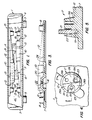
- Fig. 1 is a longitudinally sectional view of a complete weighing apparatus of an embodiment of the present invention.
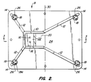
- Fig. 2 is an enlarged top view of precision casting used as both the base and the load plate in the weighing apparatus of Fig. 1.
- Fig. 3 is a cross section of the casting of Fig. 2, taken along line 3-3.
- Fig. 4 is a top view of a load arrestor of Fig. 1.
- Fig. 5 is a cross section of the load arrestor of Fig. 3, taken along line 5-5.
- a weighing apparatus 1 made according to the present invention includes a rectangular base platform 4, to which four feet 5 are attached adjacent each corner.
- a base 7 is mounted on the base platform 4 using, for example, screws (not shown).
- a load cell 9 is mounted to the base 7 by pair of fasteners 13, preferably screws.
- the load cell 9 is typically load cell Model No. 1015F15-505 manufactured by Tedla, Inc. (Canoga Park, CA).
- a load plate 11 is placed on the load cell 9 and is mounted to the load cell 9 by a pair of fasteners 13 in the same manner as the base 4 and load cell 9 are mounted together.
- the load plate 9 and base 7 are preferably identical precision castings which require no further machining.
- a protective cover 3 is then placed over the assembly comprising the base 9, load cell 9, and load plate 11.
- the cover 3 includes a load bearing surface 15, which is associated with the load plate 11, and on which the object to be weighed is placed.
- Figs. 2 and 3 show a precision casting 8 that can be used for both base 7 and load plate 11.
- the casting 8 can be seen to comprise a raised ridge 10 which forms a cavity 20 in which the load cell 9 is mounted by fasteners 13 which pass through fastener holes 16.
- the load cell 9 When the load cell 9 is mounted on the casting it rests on raised surface 22 and not on main surface 24 of the casting 8.
- Structural ridges 12 provided added strength to the casting 8.
- a pin support 18 is positioned adjacent each corner 14 of the casting 8.
- the castings 8 are formed such that the casting is simply rotated 180° along its transverse axis 30 to be used as both a base 7 and load plate 11.
- the longitudinal symmetry of the casting is exploited to allow coincidence of the pin supports.
- Asymmetry of the pin supports prevents coincidence of the holes in overlying pin supports.
- each load arrestor 17 comprises a pin support 18 having three holes 19, 19a, and 19b, each hole having a different effective depth. Between the holes 19, 19a and 19b are lands 26, 26a, and 26b that contact the pin 21 of the corresponding pin support 18. In particular, a pin 21 placed in hole 19 of pin support 18 on base 7 will contact land 26 on the overlylng pin support 18 on the load plate 11. Similarly, a pin 21 placed in holes 19a or 19b will contact lands 26a or 26b, respectively. The holes are cast so as to accept a standard 1/8" x 1" dowel pin. Each hole 19 has a counterbored region 23, the size of which varies with the depth of the hole 19. Typically, the deepest hole will have the largest counterbored region whereas the shallowest hole 19 will have no counterbored region.
- a pin 21 is placed in one of the holes 19, 19a or 19b of the pin support 18 of each of the four load arrestors 17 in the base 7.
- the effective depth of the holes 19, 19a or 19b determines the degree of movement of the load plate 11 with respect to the base 9. If the maximum travel of load plate 11 is to be changed, pins 21 are simply placed in a different hole. Alternatively, different length pins 21 can be placed in the same or a different hole.
Landscapes
- Physics & Mathematics (AREA)
- General Physics & Mathematics (AREA)
- Electromagnetism (AREA)
- Measurement Of Force In General (AREA)
Applications Claiming Priority (2)
| Application Number | Priority Date | Filing Date | Title |
|---|---|---|---|
| US07/628,302 US5048624A (en) | 1990-12-14 | 1990-12-14 | Adjustable load arrestor for weighing apparatus |
| US628302 | 1990-12-14 |
Publications (3)
| Publication Number | Publication Date |
|---|---|
| EP0490314A2 true EP0490314A2 (fr) | 1992-06-17 |
| EP0490314A3 EP0490314A3 (en) | 1992-11-25 |
| EP0490314B1 EP0490314B1 (fr) | 1996-02-28 |
Family
ID=24518320
Family Applications (1)
| Application Number | Title | Priority Date | Filing Date |
|---|---|---|---|
| EP91121079A Expired - Lifetime EP0490314B1 (fr) | 1990-12-14 | 1991-12-09 | Protection réglable contre surcharge pour dispositif de pesage |
Country Status (3)
| Country | Link |
|---|---|
| US (1) | US5048624A (fr) |
| EP (1) | EP0490314B1 (fr) |
| DE (1) | DE69117459T2 (fr) |
Cited By (1)
| Publication number | Priority date | Publication date | Assignee | Title |
|---|---|---|---|---|
| EP0603912A1 (fr) * | 1992-12-24 | 1994-06-29 | Pitney Bowes Inc. | Mécanisme pour prévenir la surcharge d'une balance |
Families Citing this family (4)
| Publication number | Priority date | Publication date | Assignee | Title |
|---|---|---|---|---|
| US5646376A (en) * | 1994-06-09 | 1997-07-08 | Intercomp Company | Aircraft weighing scale with improved base, platform and load cell mounting assembly |
| US6900398B1 (en) * | 2004-08-04 | 2005-05-31 | Lanny R. Lee | Floor scales |
| DE102015010418B4 (de) * | 2015-08-11 | 2024-06-06 | Fresenius Medical Care Deutschland Gmbh | Peritonealdialysegerät |
| CN111244926B (zh) * | 2020-01-15 | 2021-12-24 | 许继集团有限公司 | 一种可用于混合直流输电的可控避雷器 |
Family Cites Families (12)
| Publication number | Priority date | Publication date | Assignee | Title |
|---|---|---|---|---|
| US4055227A (en) * | 1975-10-03 | 1977-10-25 | The A. H. Emery Company | Heavy duty hydraulic weighing apparatus |
| US4361199A (en) * | 1980-07-01 | 1982-11-30 | Gse, Inc. | Overload protection for a weigh scale having a flexure beam |
| US4319652A (en) * | 1980-08-11 | 1982-03-16 | Guertin Joseph R | Weigh scale |
| US4313510A (en) * | 1980-11-24 | 1982-02-02 | General Electric Company | Weighing scale with dynamic zero error correction |
| US4396079A (en) * | 1981-07-29 | 1983-08-02 | Sensor Developments, Inc. | Weighing system |
| US4420054A (en) * | 1981-10-23 | 1983-12-13 | Interface, Inc. | Weighing apparatus with overload protection for off-center loading |
| CH656711A5 (de) * | 1982-07-16 | 1986-07-15 | Mettler Instrumente Ag | Waegezelle. |
| US4515232A (en) * | 1983-11-07 | 1985-05-07 | Hottinger Baldwin Measurements, Inc. | Platform transducer beams |
| US4540057A (en) * | 1984-06-07 | 1985-09-10 | Pitney Bowes Inc. | Adjustable inclined plane downstop for a load cell |
| US4574898A (en) * | 1984-06-07 | 1986-03-11 | Pitney Bowes Inc. | Scale having an overload protection means for attaching a platform to a load transducer and for protecting against excessive torsion loads |
| JPS61262621A (ja) * | 1985-05-16 | 1986-11-20 | Tokyo Electric Co Ltd | ロ−ドセル秤 |
| US4724914A (en) * | 1987-08-17 | 1988-02-16 | Pelouze Scale Company | Weighing scale having a shock-absorbing transducer support |
-
1990
- 1990-12-14 US US07/628,302 patent/US5048624A/en not_active Expired - Fee Related
-
1991
- 1991-12-09 EP EP91121079A patent/EP0490314B1/fr not_active Expired - Lifetime
- 1991-12-09 DE DE69117459T patent/DE69117459T2/de not_active Expired - Fee Related
Cited By (1)
| Publication number | Priority date | Publication date | Assignee | Title |
|---|---|---|---|---|
| EP0603912A1 (fr) * | 1992-12-24 | 1994-06-29 | Pitney Bowes Inc. | Mécanisme pour prévenir la surcharge d'une balance |
Also Published As
| Publication number | Publication date |
|---|---|
| US5048624A (en) | 1991-09-17 |
| EP0490314A3 (en) | 1992-11-25 |
| EP0490314B1 (fr) | 1996-02-28 |
| DE69117459D1 (de) | 1996-04-04 |
| DE69117459T2 (de) | 1996-07-18 |
Similar Documents
| Publication | Publication Date | Title |
|---|---|---|
| CA1216868A (fr) | Compensateur de desaxement sur couteau de charge | |
| CA1108197A (fr) | Bas-cule a couteaux de charge | |
| CA1043318A (fr) | Isolateur antivibrations reagissant aux charges | |
| US4261429A (en) | Unitized weighing apparatus and method for making such an apparatus | |
| US5824897A (en) | Blade static balancing fixture | |
| US6365847B1 (en) | Weight sensor | |
| US5190117A (en) | Load cell supporting member and weighing scale incorporating the same | |
| US5923000A (en) | Shock protection device for a force measuring apparatus | |
| US4540057A (en) | Adjustable inclined plane downstop for a load cell | |
| EP0490314B1 (fr) | Protection réglable contre surcharge pour dispositif de pesage | |
| US4420054A (en) | Weighing apparatus with overload protection for off-center loading | |
| US4419902A (en) | Constant strain load cell | |
| US4453607A (en) | Weight scale with side load protection | |
| US4453606A (en) | Low profile weigh scale | |
| US4479561A (en) | Weighing cell | |
| US4778017A (en) | Weighing scale having a shock-absorbing platform support | |
| US4088015A (en) | Force measuring apparatus with mounting arrangement | |
| JP3534905B2 (ja) | ヘルスメータ用ロードセル | |
| US5072799A (en) | Load cell supporting member and weighing scale incorporating the same | |
| JPH09196284A (ja) | 荷重を指示する機械類取付け用パッド | |
| JP3243025B2 (ja) | 2ビーム型ロードセルの製造方法 | |
| US7091428B2 (en) | Weighing apparatus with Roberval mechanism | |
| US5119896A (en) | Load cell supporting member and weighing scale incorporating the same | |
| JPS6311611Y2 (fr) | ||
| US4368792A (en) | Weighing system |
Legal Events
| Date | Code | Title | Description |
|---|---|---|---|
| PUAI | Public reference made under article 153(3) epc to a published international application that has entered the european phase |
Free format text: ORIGINAL CODE: 0009012 |
|
| AK | Designated contracting states |
Kind code of ref document: A2 Designated state(s): DE FR GB |
|
| PUAL | Search report despatched |
Free format text: ORIGINAL CODE: 0009013 |
|
| AK | Designated contracting states |
Kind code of ref document: A3 Designated state(s): DE FR GB |
|
| RAP1 | Party data changed (applicant data changed or rights of an application transferred) |
Owner name: NEOPOST INDUSTRIE |
|
| 17P | Request for examination filed |
Effective date: 19930518 |
|
| 17Q | First examination report despatched |
Effective date: 19940718 |
|
| GRAA | (expected) grant |
Free format text: ORIGINAL CODE: 0009210 |
|
| AK | Designated contracting states |
Kind code of ref document: B1 Designated state(s): DE FR GB |
|
| REF | Corresponds to: |
Ref document number: 69117459 Country of ref document: DE Date of ref document: 19960404 |
|
| ET | Fr: translation filed | ||
| PLBE | No opposition filed within time limit |
Free format text: ORIGINAL CODE: 0009261 |
|
| STAA | Information on the status of an ep patent application or granted ep patent |
Free format text: STATUS: NO OPPOSITION FILED WITHIN TIME LIMIT |
|
| 26N | No opposition filed | ||
| REG | Reference to a national code |
Ref country code: GB Ref legal event code: IF02 |
|
| PGFP | Annual fee paid to national office [announced via postgrant information from national office to epo] |
Ref country code: DE Payment date: 20051212 Year of fee payment: 15 |
|
| PGFP | Annual fee paid to national office [announced via postgrant information from national office to epo] |
Ref country code: FR Payment date: 20051219 Year of fee payment: 15 |
|
| PGFP | Annual fee paid to national office [announced via postgrant information from national office to epo] |
Ref country code: GB Payment date: 20051222 Year of fee payment: 15 |
|
| PG25 | Lapsed in a contracting state [announced via postgrant information from national office to epo] |
Ref country code: DE Free format text: LAPSE BECAUSE OF NON-PAYMENT OF DUE FEES Effective date: 20070703 |
|
| GBPC | Gb: european patent ceased through non-payment of renewal fee |
Effective date: 20061209 |
|
| REG | Reference to a national code |
Ref country code: FR Ref legal event code: ST Effective date: 20070831 |
|
| PG25 | Lapsed in a contracting state [announced via postgrant information from national office to epo] |
Ref country code: GB Free format text: LAPSE BECAUSE OF NON-PAYMENT OF DUE FEES Effective date: 20061209 |
|
| PG25 | Lapsed in a contracting state [announced via postgrant information from national office to epo] |
Ref country code: FR Free format text: LAPSE BECAUSE OF NON-PAYMENT OF DUE FEES Effective date: 20070102 |