EP0490329A1 - Système de contrôle de l'intensité lumineuse et du comportement de lampes à décharge - Google Patents
Système de contrôle de l'intensité lumineuse et du comportement de lampes à décharge Download PDFInfo
- Publication number
- EP0490329A1 EP0490329A1 EP91121150A EP91121150A EP0490329A1 EP 0490329 A1 EP0490329 A1 EP 0490329A1 EP 91121150 A EP91121150 A EP 91121150A EP 91121150 A EP91121150 A EP 91121150A EP 0490329 A1 EP0490329 A1 EP 0490329A1
- Authority
- EP
- European Patent Office
- Prior art keywords
- lamp
- voltage
- control
- brightness
- circuit
- Prior art date
- Legal status (The legal status is an assumption and is not a legal conclusion. Google has not performed a legal analysis and makes no representation as to the accuracy of the status listed.)
- Granted
Links
Images



Classifications
-
- H—ELECTRICITY
- H05—ELECTRIC TECHNIQUES NOT OTHERWISE PROVIDED FOR
- H05B—ELECTRIC HEATING; ELECTRIC LIGHT SOURCES NOT OTHERWISE PROVIDED FOR; CIRCUIT ARRANGEMENTS FOR ELECTRIC LIGHT SOURCES, IN GENERAL
- H05B41/00—Circuit arrangements or apparatus for igniting or operating discharge lamps
- H05B41/14—Circuit arrangements
- H05B41/36—Controlling
- H05B41/38—Controlling the intensity of light
- H05B41/39—Controlling the intensity of light continuously
- H05B41/392—Controlling the intensity of light continuously using semiconductor devices, e.g. thyristor
- H05B41/3921—Controlling the intensity of light continuously using semiconductor devices, e.g. thyristor with possibility of light intensity variations
- H05B41/3922—Controlling the intensity of light continuously using semiconductor devices, e.g. thyristor with possibility of light intensity variations and measurement of the incident light
-
- H—ELECTRICITY
- H05—ELECTRIC TECHNIQUES NOT OTHERWISE PROVIDED FOR
- H05B—ELECTRIC HEATING; ELECTRIC LIGHT SOURCES NOT OTHERWISE PROVIDED FOR; CIRCUIT ARRANGEMENTS FOR ELECTRIC LIGHT SOURCES, IN GENERAL
- H05B47/00—Circuit arrangements for operating light sources in general, i.e. where the type of light source is not relevant
- H05B47/10—Controlling the light source
- H05B47/17—Operational modes, e.g. switching from manual to automatic mode or prohibiting specific operations
- H05B47/172—Emergency operational modes
-
- H—ELECTRICITY
- H05—ELECTRIC TECHNIQUES NOT OTHERWISE PROVIDED FOR
- H05B—ELECTRIC HEATING; ELECTRIC LIGHT SOURCES NOT OTHERWISE PROVIDED FOR; CIRCUIT ARRANGEMENTS FOR ELECTRIC LIGHT SOURCES, IN GENERAL
- H05B41/00—Circuit arrangements or apparatus for igniting or operating discharge lamps
- H05B41/14—Circuit arrangements
- H05B41/26—Circuit arrangements in which the lamp is fed by power derived from DC by means of a converter, e.g. by high-voltage DC
- H05B41/28—Circuit arrangements in which the lamp is fed by power derived from DC by means of a converter, e.g. by high-voltage DC using static converters
-
- H—ELECTRICITY
- H05—ELECTRIC TECHNIQUES NOT OTHERWISE PROVIDED FOR
- H05B—ELECTRIC HEATING; ELECTRIC LIGHT SOURCES NOT OTHERWISE PROVIDED FOR; CIRCUIT ARRANGEMENTS FOR ELECTRIC LIGHT SOURCES, IN GENERAL
- H05B41/00—Circuit arrangements or apparatus for igniting or operating discharge lamps
- H05B41/14—Circuit arrangements
- H05B41/26—Circuit arrangements in which the lamp is fed by power derived from DC by means of a converter, e.g. by high-voltage DC
- H05B41/28—Circuit arrangements in which the lamp is fed by power derived from DC by means of a converter, e.g. by high-voltage DC using static converters
- H05B41/282—Circuit arrangements in which the lamp is fed by power derived from DC by means of a converter, e.g. by high-voltage DC using static converters with semiconductor devices
- H05B41/2825—Circuit arrangements in which the lamp is fed by power derived from DC by means of a converter, e.g. by high-voltage DC using static converters with semiconductor devices by means of a bridge converter in the final stage
- H05B41/2827—Circuit arrangements in which the lamp is fed by power derived from DC by means of a converter, e.g. by high-voltage DC using static converters with semiconductor devices by means of a bridge converter in the final stage using specially adapted components in the load circuit, e.g. feed-back transformers, piezoelectric transformers; using specially adapted load circuit configurations
-
- H—ELECTRICITY
- H05—ELECTRIC TECHNIQUES NOT OTHERWISE PROVIDED FOR
- H05B—ELECTRIC HEATING; ELECTRIC LIGHT SOURCES NOT OTHERWISE PROVIDED FOR; CIRCUIT ARRANGEMENTS FOR ELECTRIC LIGHT SOURCES, IN GENERAL
- H05B41/00—Circuit arrangements or apparatus for igniting or operating discharge lamps
- H05B41/14—Circuit arrangements
- H05B41/26—Circuit arrangements in which the lamp is fed by power derived from DC by means of a converter, e.g. by high-voltage DC
- H05B41/28—Circuit arrangements in which the lamp is fed by power derived from DC by means of a converter, e.g. by high-voltage DC using static converters
- H05B41/295—Circuit arrangements in which the lamp is fed by power derived from DC by means of a converter, e.g. by high-voltage DC using static converters with semiconductor devices and specially adapted for lamps with preheating electrodes, e.g. for fluorescent lamps
-
- H—ELECTRICITY
- H05—ELECTRIC TECHNIQUES NOT OTHERWISE PROVIDED FOR
- H05B—ELECTRIC HEATING; ELECTRIC LIGHT SOURCES NOT OTHERWISE PROVIDED FOR; CIRCUIT ARRANGEMENTS FOR ELECTRIC LIGHT SOURCES, IN GENERAL
- H05B41/00—Circuit arrangements or apparatus for igniting or operating discharge lamps
- H05B41/14—Circuit arrangements
- H05B41/26—Circuit arrangements in which the lamp is fed by power derived from DC by means of a converter, e.g. by high-voltage DC
- H05B41/28—Circuit arrangements in which the lamp is fed by power derived from DC by means of a converter, e.g. by high-voltage DC using static converters
- H05B41/295—Circuit arrangements in which the lamp is fed by power derived from DC by means of a converter, e.g. by high-voltage DC using static converters with semiconductor devices and specially adapted for lamps with preheating electrodes, e.g. for fluorescent lamps
- H05B41/298—Arrangements for protecting lamps or circuits against abnormal operating conditions
- H05B41/2981—Arrangements for protecting lamps or circuits against abnormal operating conditions for protecting the circuit against abnormal operating conditions
- H05B41/2983—Arrangements for protecting lamps or circuits against abnormal operating conditions for protecting the circuit against abnormal operating conditions against abnormal power supply conditions
-
- H—ELECTRICITY
- H05—ELECTRIC TECHNIQUES NOT OTHERWISE PROVIDED FOR
- H05B—ELECTRIC HEATING; ELECTRIC LIGHT SOURCES NOT OTHERWISE PROVIDED FOR; CIRCUIT ARRANGEMENTS FOR ELECTRIC LIGHT SOURCES, IN GENERAL
- H05B41/00—Circuit arrangements or apparatus for igniting or operating discharge lamps
- H05B41/14—Circuit arrangements
- H05B41/36—Controlling
-
- H—ELECTRICITY
- H05—ELECTRIC TECHNIQUES NOT OTHERWISE PROVIDED FOR
- H05B—ELECTRIC HEATING; ELECTRIC LIGHT SOURCES NOT OTHERWISE PROVIDED FOR; CIRCUIT ARRANGEMENTS FOR ELECTRIC LIGHT SOURCES, IN GENERAL
- H05B41/00—Circuit arrangements or apparatus for igniting or operating discharge lamps
- H05B41/14—Circuit arrangements
- H05B41/36—Controlling
- H05B41/38—Controlling the intensity of light
- H05B41/39—Controlling the intensity of light continuously
- H05B41/392—Controlling the intensity of light continuously using semiconductor devices, e.g. thyristor
- H05B41/3921—Controlling the intensity of light continuously using semiconductor devices, e.g. thyristor with possibility of light intensity variations
-
- H—ELECTRICITY
- H05—ELECTRIC TECHNIQUES NOT OTHERWISE PROVIDED FOR
- H05B—ELECTRIC HEATING; ELECTRIC LIGHT SOURCES NOT OTHERWISE PROVIDED FOR; CIRCUIT ARRANGEMENTS FOR ELECTRIC LIGHT SOURCES, IN GENERAL
- H05B41/00—Circuit arrangements or apparatus for igniting or operating discharge lamps
- H05B41/14—Circuit arrangements
- H05B41/36—Controlling
- H05B41/38—Controlling the intensity of light
- H05B41/39—Controlling the intensity of light continuously
- H05B41/392—Controlling the intensity of light continuously using semiconductor devices, e.g. thyristor
- H05B41/3921—Controlling the intensity of light continuously using semiconductor devices, e.g. thyristor with possibility of light intensity variations
- H05B41/3925—Controlling the intensity of light continuously using semiconductor devices, e.g. thyristor with possibility of light intensity variations by frequency variation
-
- H—ELECTRICITY
- H05—ELECTRIC TECHNIQUES NOT OTHERWISE PROVIDED FOR
- H05B—ELECTRIC HEATING; ELECTRIC LIGHT SOURCES NOT OTHERWISE PROVIDED FOR; CIRCUIT ARRANGEMENTS FOR ELECTRIC LIGHT SOURCES, IN GENERAL
- H05B47/00—Circuit arrangements for operating light sources in general, i.e. where the type of light source is not relevant
- H05B47/10—Controlling the light source
- H05B47/175—Controlling the light source by remote control
- H05B47/18—Controlling the light source by remote control via data-bus transmission
Definitions
- the invention relates generally to an electronic ballast (EVG) for fluorescent lamps.
- EMG electronic ballast
- circuit arrangements within the electronic ballast and a method for controlling the brightness and the operating behavior of fluorescent lamps.
- Modern electronic ballasts are used to control fluorescent lamps. On the one hand the fluorescent lamps are operated more gently and on the other hand the efficiency of such lamp types can be increased.
- An electronic ballast regularly has the features specified in the preamble of claim 1.
- a supply voltage which can be a direct or alternating voltage, is fed to a rectifier and an intermediate circuit capacitor via a mains input filter. If the device is operated exclusively with DC voltage, the latter rectifier can be omitted.
- a high intermediate circuit voltage U0 is formed on the intermediate circuit capacitor, which is of the order of magnitude of approximately 300 V with a conventional mains voltage supply of 220 V.
- An AC voltage generator is connected to the DC link, which is formed by a half-bridge or full-bridge inverter. It outputs a frequency-variable output voltage to an output load circuit which, unless a half-bridge circuit with an artificial voltage means tap is provided, has a series resonance circuit. The discharge path of the gas discharge lamp or fluorescent lamp to be controlled is in series with the series resonance circuit.
- the output frequency of the inverter is approximately 10 kHz - 50 kHz.
- the efficiency of the connected fluorescent lamps is increased compared to operation on the 50 Hz supply network.
- An increased luminous efficiency is achieved with the same electrical power consumption.
- the inductance of the series resonant circuit on the output side of the inverter can be kept small.
- the variable frequency control allows brightness control of the fluorescent lamp, which is difficult to regulate (dimmable) on the normal network.
- An ignition of the fluorescent lamp can also be prepared and initiated via the frequency control.
- the aforementioned ignition process also includes a so-called warm start, in which the heating filaments of the fluorescent lamp are preheated before the lamp is subjected to a high ignition voltage due to resonance phenomena, which leads to ignition and thus to the operation of the gas discharge lamp.
- the variation of the frequency, which controls the ignition allows an almost infinitely variable brightness control within wide limits even during operation of the gas discharge lamp. Such a continuous and continuous control of the brightness requires special measures due to the negative internal resistance of the fluorescent lamp in operation.
- An essential aspect for the development of a modern electronic ballast is therefore a control option that is as versatile as possible, in particular a brightness control. This with regard to the operating behavior and the brightness control of the fluorescent lamps connected to a respective electronic ballast.
- the method according to the invention makes it possible to handle the control functions and the brightness control particularly precisely and comfortably.
- a control and regulating device is provided, which takes over all essential control, regulating and monitoring functions for a decentralized ECG. It is assigned a transmitting and receiving device that serves as an interface to the outside. Control commands and brightness commands can be supplied here, which are executed by the control and regulating device, depending on the currently valid process variables (measured variables) of the respective decentralized ECG.
- a pair of fluorescent lamps are advantageously operated on an AC voltage generator in a respective decentralized ECG. This corresponds to a so-called two-lamp electronic ballast.
- the control and regulation device allows a targeted increase in the lifespan of the fluorescent lamps and the granting of safety interests.
- the operating behavior and the respective operating state of the fluorescent lamps supplied by an electronic ballast can be precisely controlled and monitored by means of the aforementioned control and regulating device. In this way, warm start, ignition, dimming and switch-off processes (IGNITION, DIMM, OFF, ON) are strung together with high precision and gentle on the lamp. Inadmissible operating conditions are avoided, and sufficient heating of the heating coils is ensured before each ignition.
- DIMM dimming and switch-off processes
- the entire ECG can also be shut down (SLEEP) if no brightness is required for a long period of time. In this state, the ECG consumes only a minimal amount of power. Avoidable losses are actually avoided.
- EMERGENCY emergency operation
- the lamp assumes an emergency lighting light level. This can be specified locally on the respective device. It is automatically activated under certain hazard conditions.
- the transmitting and receiving device is advantageously connected to a central control device via a bidirectional bus line (claim 4).
- a bidirectional bus line (claim 4).
- the control unit also provides operating status information. Errors that occur in the lighting system are recognized and displayed on the basis of error messages sent by the decentralized ECGs via the bidirectional bus line have been sent to the central control unit. This simplifies and speeds up maintenance work.
- a variety of monitoring functions are already provided decentrally, such as overvoltage and undervoltage monitoring (claim 6). It noticeably increases the lifespan of the fluorescent lamps.
- the brightness control of the decentralized ECGs takes place via serial digital control words which represent control commands or brightness data information (claim 13).
- serial digital control words which represent control commands or brightness data information (claim 13).
- the coupling of the transmitting and receiving devices to the bus line is advantageously effected by a differentiating element. It provides a strong attenuation of the 50 Hz network frequencies and works with very low input currents. The attenuation of the network frequencies goes so far that reverse polarity protection is also provided, the application of 220 V to the bus line remains without damage (claim 15).
- the fluorescent lamps are switched to dimmed operation after an ignition process, there may be short-term light pulses. They have their cause in the energy of the ignition process stored in the output circuit, which then manifests itself undesirably as a light pulse in dimmed operation.
- This can be remedied by extending the glow phase - which actually shortens the lifespan - between ignition and stationary operation (claim 16).
- an actual shortening of the service life is avoided by the fact that the glow area is only extended at low brightness values. The greater the brightness, the shorter the glow phase and the faster the transition from ignition to normal operation (claim 17).
- the control and regulating device is supplied with a plurality m of measured variables from the electronic ballast, a large number of operating states and possibly dangerous states can be identified and avoided therefrom. Furthermore, real power control is possible, which works regardless of the lamp type (for example, argon lamps or krypton lamps).
- the lamp brightness control is advantageously achieved by frequency modulation (claim 21) or by a combination of frequency modulation and duty cycle change (claim 12).
- Monitoring also includes checking the heating coil currents of the fluorescent lamps. They allow a precise determination of whether certain lamps are defective or possibly not installed at all (claim 23).
- the inductive balancing element effects a symmetrical operation of both fluorescent lamps (claim 28).
- the lamp-specific heat exchangers which are connected with their primary winding to the AC voltage output circuit, enable voltage-controlled coil heating (claim 31).
- the control and regulating device can draw conclusions about the nature of the heating coil at any time via primary current detection and thus identify already damaged fluorescent lamps or fluorescent lamps that will soon fail (claim 32).
- the mains voltage U N is supplied to the input circuit 20 (rectifier circuit), possibly via a switch S1. This generates the intermediate circuit voltage U0, U dc , which is fed to the AC voltage generator 30 (inverter).
- the AC voltage generator 30 outputs its high-frequency output voltage U HF to an output load circuit 40 which contains one or more fluorescent lamps LA1, LA2.
- a plurality of system measured values can be taken from both the AC voltage generator 30 and the load circuit 40. Together, the measured values are fed to a control and regulating circuit 17, which in turn generates the digital control signals for the inverter 30.
- control and regulating device 17 is also assigned a transmitting and receiving device 10, which is connected via a bus line 12 to other electronic ballasts and / or to a central control device 50.
- a plurality of electronic ballasts 60-1, 60-2, 60-3, ..., 60-i are connected to a common bus line 12. All ECGs are connected via this bus line to the central control device 50, to which a display unit 51 is assigned. Via bus line 12, it is now possible to control one or more of the aforementioned electronic ballasts and to transmit commands to them, such as switching off, switching on, igniting or the like. Brightness values can also be preset and, in return, error information can be queried from the individual devices. The control unit 50 is thus informed of the overall system status at all times, which means that a high degree of operational reliability can be guaranteed and accelerated maintenance of the decentralized ECGs or for their fluorescent lamps is possible.
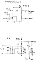
- FIG. 3 shows the control and regulating device 17 as an integrated circuit.
- the plurality of measured values m which correspond to the process signals of FIG. 1 are fed to it. It gives two digital control signals for the output stage transistors of the inverter 30, which are amplified and potential-shifted via a driver circuit 31.
- control and regulating device 17 is also supplied with n target values. These influence the predeterminable control behavior. Furthermore, a transmitting and receiving device 10 is provided as part of the control and regulating circuit 17 or separately, which is connected directly or by means of a coupling circuit to the bus line 12. It forms the serial interface, which enables the control and regulating device to transmit error and operating status information to the central control device 50.
- Setpoints can also be supplied to this transmitting and receiving device 10, which they pass on to the control and regulating circuit 17 after appropriate preparation.
- Setpoints can be, for example, the emergency lighting level (NOT), the minimum brightness level (MIN) and the maximum brightness level (MAX), within the latter of which the specifiable brightness level (DIMM) can move during operation.
- Serial digital data words are used as command and data words and as error information words. Other value lengths are possible.
- An address is assigned to each decentralized ECG, which makes it possible to address individual ECGs via the address of the transmitting and receiving device 10 and to query information from them or to issue commands to them.
- the bidirectional mode of operation of the bus line 12 enables a large number of decentralized electronic ballasts to be connected to a central control unit (50) without problems and with little effort.
- FIG. 4 shows a basic circuit diagram of an input circuit as can be used for supplying the alternating voltage generator 30 from a supply network with the voltage U N.
- the input circuit consists of capacitive input filters and possibly a harmonic choke.
- the Y-circuit capacitors are used for radio interference suppression.
- a surge arrester or a VDR is connected in parallel. This is followed by a full-wave rectifier, which can be omitted if the device is operated with direct voltage.
- Downstream of the rectifier is an intermediate circuit capacitor C4, which charges up to approx. 300 V with a residual ripple of approx. 10% at 220 V mains voltage.
- the intermediate circuit voltage U0 Due to a crest factor to be kept low, the intermediate circuit voltage U0 should be smoothed well.
- a voltage divider R18, R28 Parallel to the intermediate circuit capacitor C4 is a voltage divider R18, R28, from which a measurement signal proportional to the intermediate circuit voltage can be tapped.
- a signal which is proportional to the supply voltage is detected at a low-pass filter R21, C25 and, like the intermediate-circuit voltage-dependent measurement signal, is fed to the control and regulating device 17. Both measurement signals are used to monitor the supply voltage and thus the operational safety of the ECG.
- FIG. 5 shows an exemplary embodiment of a load circuit 40 according to the invention with a heat exchanger L5 for preheating the filaments of the fluorescent lamp LA1.
- the exemplary embodiment of the invention has a pair of these branches, that is to say two fluorescent lamps LA1, LA2 at an AC voltage output which emits the high-frequency AC voltage U HF between the series-connected power switching transistors V21 and V28.
- the AC voltage generator is supplied with an intermediate circuit voltage U dc from the input circuit 20 shown in FIG. 4. Since the fluorescent lamps have a negative internal resistance during operation, they must be supplied with high voltage peaks during the ignition process (ZÜND) and with appropriate heating energy when heating the filaments.
- a series resonance circuit L2, C15 leads via a balancing element TR1, which will be explained later, to the discharge path H2, H4 of the fluorescent lamp. Furthermore, a measuring resistor R32 is connected in series with the fluorescent tube, at which a voltage proportional to the lamp current I L1 is tapped and fed to the control and regulating circuit 17.
- An ignition capacitor C17 is connected to ground (ZERO) between coil L2 and capacitor C15.
- Parallel to the ignition capacitor C17 is also the primary winding of the heat exchanger L5 and in series with this a Zener diode V15 and a measuring resistor R10.
- a voltage proportional to the heating coil current I W1 is tapped from the latter and fed to the control and regulating circuit 17 as a further system measurement variable. Since the inverter 30 impresses an output voltage and the heat exchanger is essentially parallel to the fluorescent lamp LA1, a voltage is impressed on its secondary windings via the heat exchanger. The two secondary windings each supply one of the two heating coils H1, H2 and H3, H4 potential-free. The sum of the heating coil currents I W1 is thus measured at the primary-side measuring resistor R10.
- the Zener diode V15 which is still connected in series, generates a direct current component in the primary winding of L5, which, however, is not transmitted, but is missing in the lamp current I L1 and thus supplies the discharge of the lamp with an additional direct current component in the order of approximately 1% of the actual discharge current .
- the "running layers” consist in particular of light / dark zones which occur during dimming and run along the tube at a predetermined speed. A superimposition of low direct current accelerates this running effect in such a way that it no longer has a disturbing effect.
- the inverter 30 is operated at a high frequency f max , so that an AC voltage occurs at C17 which is not suitable for igniting the lamp LA1.
- the filaments of the lamp are heated via L5, the lamp absorbing a high and then a lower heating current due to the thermistor effect of the filaments.
- the ignition (IGNITION) of the lamp is initiated.
- the frequency f of the inverter 30 is reduced so that it comes closer to the resonance frequency f of the output series resonance circuit L2, C15. This creates a voltage surge at C17, which is of the order of approximately 750 V (peak). This will ignite a functional lamp.
- the series resonance circuit L2, C15 or L3, C16 is strongly damped. On the one hand, this causes a shift in the resonance frequencies f0 and, on the other hand, an immediate drop in the AC voltage at the respective lamp. The decrease is detected by the control and regulating circuit 17 via the voltage divider R27, R25 connected in parallel to the lamp. This then initiates the actual operating phase (DIMM) of the lamps.
- DIMM actual operating phase
- the frequency f of the inverter 30 is regulated so that the lamp output corresponds to the predetermined target value, ie the desired brightness level.
- the operating frequency of the alternating voltage generator 30 can also be shifted to values which are in the order of magnitude of the heating frequency or above.
- An output frequency can also be set at a maximum power (MAX) is below the ignition frequency, but still above the resonance frequency of the series resonance circuit L2, C15.
- MAX maximum power
- the operating state of the lamp circuit 14 can vary greatly depending on the lamp used, for example argon or krypton lamps, or depending on the lamp power selected.
- the combination of the capacitor C24 and the diodes V30, V31 results in a frequency-dependent damping of the output circuit when the voltage rises. It is particularly important when there are high frequencies and high impedances, e.g. if there is no lamp or if the filament is already warm.
- the wiring of this type helps to limit the voltage rise when the lamp is not ignited or missing when it is undesirable.
- C24 is selected so that the damping remains small enough at the time of ignition.
- Fig. 6 shows the output circuit of Fig. 5 for the two-lamp - two fluorescent lamps on an inverter - operation.
- the symmetry transformer TR1 is also shown here in full. Each winding is traversed by one of the two lamp currents. This happens in opposite directions, so that in the event of a deviation in the current amplitude, a resulting magnetization occurs, which induces a voltage in the inductive element which has a symmetrical effect.
- Such a transformer is advantageous if the two lamps would burn differently bright in the dimmed state due to component tolerances and lamp tolerances as well as different temperature conditions.
- the symmetry element TR1 avoids this in the case of two-lamp luminaires. If several arrays of lamps are operated at an AC generator output, such a balancing element TR1 must be provided for each pair.
- a signal proportional to the lamp current is obtained from them, which signal can be multiplied in the control and regulating circuit 17 by the aforementioned lamp voltage signal is. In this way it is ensured that at any time of the actual lamp power is P or E brightness proportional signal is available, which can be preset to a precise brightness control as the feedback.
- FIG. 7 shows the inverter 30 in more detail with its output power transistors V28, V21. Between them, the high-frequency AC voltage U HF is output to the load circuit 40 explained above.
- the two power transistors are controlled via a control circuit 31, which receives its control signals from the control and regulating circuit 17. Possibly. unbalanced turn-off / turn-on delays come into consideration for the respective transistors, so that a common conduction of both transistors V21, V28 can be avoided in principle.
- the upper transistor is supplied via a bootstrap circuit (not shown), the lower transistor and the system controller 10, 17, 31 receive their drive voltage via a series resistor and a smoothing capacitor C5 from the intermediate circuit voltage U0.
- the current that can be supplied to the smoothing capacitor C5 through the series resistor or a current source I q is sufficient to supply the IC31 and the control and regulating circuit 17 in the switched-off mode (SLEEP).
- the load circuit 40 of the inverter 30 is in an impermissible capacitive range. It represents a danger for the controlling inverter.
- a phase angle analysis can also be used in which the load current I L1 is set in relation to the inverter branch current I max and from this the relative phase of both currents is used to detect the operating state.
- Detection of an impermissible capacitive operating behavior is answered by the control circuit 17 by increasing the operating frequency f of the inverter 30, with which the load circuit 40 is again operated inductively.
- the above-mentioned capacitive mode of operation mainly occurs with a low supply voltage. With the branch current detection, destruction of components can be safely avoided.
- the digital interface 10 shows the transmitting and receiving device 10 and the coupling filter connected upstream of it, with which the bus coupling to the control line 12 takes place.
- the digital interface 10 is given the setpoints for minimum, maximum and emergency lighting brightness (U NOT , U MIN , U MAX ).
- a digital input DAT is provided, via which both the control signals arrive from a central control device to the decentralized ECG and the error signals are transmitted from the decentralized ECG to the central control device.
- the serial interface enables remote control of the electronic ballast by means of a digital command signal or command word.
- An 8 bit data word is provided as such a digital signal.
- FIG. 8c An advantageous further development of this circuit is shown in FIG. 8c.
- the circuit is protected against polarity reversal by using a secondary winding with center tap.
- Optical coupling can also be used, but this has an increased power consumption.
- control signals 255 (corresponding to 8 bit) brightness values are provided as control signals.
- the control signal "OFF”, represented by the binary word “zero” is also possible. With the aforementioned signal OFF, the entire ECG switches to an energy-saving shutdown mode (SLEEP) immediately or after a short period of time. In him the Measuring current consumption of the entire ballast minimal.
- the inverter 30 and the control circuit 31 are shut down and, after a slight further time delay, if necessary, the essential assemblies of the control and regulating circuit 17. Only the receiving circuit of the transmitting and receiving device 10 and the monitoring circuit for the detection of an emergency operation (EMERGENCY) remain activated. The total circuit power thus drops below 1 W.
- control and regulating circuit 17 immediately carries out the switch-on sequence, which, with preheating and ignition process (IGNITION), transfers to steady-state operation and is used for one immediate setting of the desired brightness value (DIMM) is ensured.
- IGNITION preheating and ignition process
- control and regulating circuit 17 is also responsible for extracting the information from all of the aforementioned process variables which are important for monitoring and controlling the electronic ballast.
- the various operating states of the fluorescent tube can also be distinguished by the measured variables.
- the measured process variables and those used for checking are summarized below: Supply voltage U ac , U N , Under / overvoltage U Nmin , U Nmax , Battery voltage U B , DC link voltage U0, U dc , Lamp current / operating current I L1 , I L2 , Lamp voltage U L1 , U L2 , Output voltage U HF , Output current I HF , Spiral current I W1 , I W2 , AC generator branch current I chap .
- the control and regulating circuit 17 switches off all functions when the voltage becomes too high, and can only function again when the voltage has been switched off and on again.
- An emergency mode switchover to a predeterminable emergency lighting brightness takes place, for example, when a DC voltage U N is detected by the control circuit 17 via the usual AC supply input of the switch-on circuit 20 and via the sensors R21, C25 (FIG. 4).
- a counter logic is used, which initiates emergency operation if the specified threshold value is not exceeded or undershot. This can happen after a specified dead time that bridges individual, possibly missing, half-waves.
- an emergency voltage supply U B which is obtained from batteries or a generator, is placed on the mains voltage line.
- the ECGs recognize this automatically.
- the brightness of the fluorescent lamps is no longer specified by the digitally specified brightness value DIMM, but by a trim value that can be specified locally on the device and can be specified via the input U NOT .
- the ECG is in switch-off mode (SLEEP) when this emergency operation occurs, ie the lamp and inverter are switched off, it will first carry out the normal ignition process (IGNIT) in order to subsequently switch to the emergency operating brightness.
- SLEEP switch-off mode
- the electronic ballast When the end of the emergency operating state is recognized, the electronic ballast returns to the previous state; this can be the OFF state if the electronic ballast was previously there. However, this can also be the original brightness value (DIMM), if this was available before requesting emergency operation.
- DIMM original brightness value
- the detection of the filament current detects whether either a lamp is not inserted or one of the two filaments is broken.
- the inverter 30 is operated at its maximum frequency f max , which on the one hand results in the heating current still flowing when the defective lamp has been replaced and on the other hand reduces the voltage on the defective lamp to the smallest possible extent .
- f max maximum frequency
- the inductive part of the series resonance circuit in the output becomes so high at the above-mentioned high frequency f max with respect to the capacitive resistance of the ignition capacitor C17 that the voltage at the output is limited to harmless values and there is no danger for the maintenance personnel.
- the ignition process (IGNITION) is initiated without waiting for the preheating time to elapse.
- the internal sequence control in the control and regulating circuit 17 also limits the number of start attempts to two and sets (sends) whenever there is an error, e.g. B. the lamp is missing if a filament break or a gas defect is present, an error signal via the transmitting and receiving device 10 on the bidirectional bus 12. This also applies in emergency mode, since emergency mode cannot be maintained if the lamp is defective.
- an error e.g. B. the lamp is missing if a filament break or a gas defect is present
- Wiring errors that lead to a short circuit in the discharge path of the lamp can then be detected on the basis of the process signals if the lamp voltages are monitored for a predetermined minimum value. If the value falls below this specified value, as in the case of the mains overvoltage monitoring, the entire ECG is switched off.
- the unwillingness to ignite the lamp e.g. B. by gas defect, is recognized by the control and regulating circuit 17. If the lamp cannot be ignited within a predetermined ignition timing, i. H. if the voltage across the ignition capacitor C17 does not drop within this period, the said lock is activated.
- a repeat time can also be waited for after which a new attempt to start and start is made. If no ignition success is achieved here either, the control and regulating circuit 17 reacts as in the case of a broken heating coil and sets the frequency of the inverter 30 to the maximum value f max .
- FIG. 9 shows a brightness-time diagram in which the brightness of the lamp controlled by the electronic ballast according to FIG. 1 is varied as a function of time.
- maximum brightness is provided, followed by a switch-off cycle specified via the bus line 12 and the digital interface 10.
- the brightness is acc. a predetermined slope reduced to zero, then the inverter 30, its driver circuit 31 and essential parts of the control IC 17 turn off to save electricity.
- a subsequent emergency lighting condition leads - despite switched off system - for a controlled ignition and a build-up of the brightness of the lamp to the preset emergency lighting brightness (NOT).
- NOT preset emergency lighting brightness
- This can be changed via the setpoint specification U NOT for each decentralized ECG.
- the maximum and minimum brightness value (MIN, MAX) shown in FIG. 9 can be set or adjusted via a corresponding setpoint value.
- a program-controlled "soft start” is shown schematically in FIG. 10 as a brightness-time diagram.
- the ECG 60 is initially in the switched-off state (OFF).
- the "Softstart” command now leads either to an automatic, slope-controlled increase in lamp brightness - after it has been ignited - or to a program-controlled incremental increase in lamp brightness levels. In the latter case, the central control unit 50 sends incrementally increasing brightness values in certain time segments.
- the decentralized ECGs follow the requirements almost without delay. This enables a change-rate-controlled (regulated) rise and fall of the decentralized light sources.
Landscapes
- Engineering & Computer Science (AREA)
- Power Engineering (AREA)
- Circuit Arrangements For Discharge Lamps (AREA)
- Discharge-Lamp Control Circuits And Pulse- Feed Circuits (AREA)
- Lighting Device Outwards From Vehicle And Optical Signal (AREA)
- Regulation And Control Of Combustion (AREA)
- Medicines Containing Plant Substances (AREA)
- Investigating Or Analysing Biological Materials (AREA)
- Heterocyclic Carbon Compounds Containing A Hetero Ring Having Oxygen Or Sulfur (AREA)
Priority Applications (7)
| Application Number | Priority Date | Filing Date | Title |
|---|---|---|---|
| EP95114571A EP0701390A3 (fr) | 1990-12-07 | 1991-12-09 | Circuit pour commander l'intensité lumineuse et le mode de fonctionnement de lampes à décharge |
| EP95114759A EP0706307A3 (fr) | 1990-12-07 | 1991-12-09 | Circuit pour commander l'intensité lumineuse et le mode de functionnement de lampes à décharge |
| EP99126075A EP0989787A3 (fr) | 1990-12-07 | 1991-12-09 | Procédé et circuit de commande de l' intensité lumineuse et du comportement de lampes à décharge |
| EP99126074A EP0989786B1 (fr) | 1990-12-07 | 1991-12-09 | Procédé et circuit de commande de l' intensité lumineuse et du comportement de lampes à décharge |
| EP95114483A EP0689373A3 (fr) | 1990-12-07 | 1991-12-09 | Circuits pour commander l'intensité lumineuse et le mode de fonctionnement de lampes à décharge |
| EP95114340A EP0688153A3 (fr) | 1990-12-07 | 1991-12-09 | Procédé et circuit pour commander l'intensité lumineuse et le mode de fonctionnement de lampes à décharge |
| EP95114670A EP0701389B1 (fr) | 1990-12-07 | 1991-12-09 | Circuit pour commander l'intensité lumineuse et le mode de functionnement de lampes à décharge |
Applications Claiming Priority (2)
| Application Number | Priority Date | Filing Date | Title |
|---|---|---|---|
| DE4039161A DE4039161C2 (de) | 1990-12-07 | 1990-12-07 | System zur Steuerung der Helligkeit und des Betriebsverhaltens von Leuchtstofflampen |
| DE4039161 | 1990-12-07 |
Related Child Applications (5)
| Application Number | Title | Priority Date | Filing Date |
|---|---|---|---|
| EP95114483.1 Division-Into | 1991-12-09 | ||
| EP95114571.3 Division-Into | 1991-12-09 | ||
| EP95114340.3 Division-Into | 1991-12-09 | ||
| EP95114670.3 Division-Into | 1991-12-09 | ||
| EP95114670A Division EP0701389B1 (fr) | 1990-12-07 | 1991-12-09 | Circuit pour commander l'intensité lumineuse et le mode de functionnement de lampes à décharge |
Publications (2)
| Publication Number | Publication Date |
|---|---|
| EP0490329A1 true EP0490329A1 (fr) | 1992-06-17 |
| EP0490329B1 EP0490329B1 (fr) | 1996-04-17 |
Family
ID=6419851
Family Applications (9)
| Application Number | Title | Priority Date | Filing Date |
|---|---|---|---|
| EP91121150A Revoked EP0490329B1 (fr) | 1990-12-07 | 1991-12-09 | Système de contrÔle de l'intensité lumineuse et du comportement de lampes à décharge |
| EP95114340A Withdrawn EP0688153A3 (fr) | 1990-12-07 | 1991-12-09 | Procédé et circuit pour commander l'intensité lumineuse et le mode de fonctionnement de lampes à décharge |
| EP91121151A Expired - Lifetime EP0490330B1 (fr) | 1990-12-07 | 1991-12-09 | Circuit de commande de lampes à décharge |
| EP95114571A Withdrawn EP0701390A3 (fr) | 1990-12-07 | 1991-12-09 | Circuit pour commander l'intensité lumineuse et le mode de fonctionnement de lampes à décharge |
| EP95114759A Withdrawn EP0706307A3 (fr) | 1990-12-07 | 1991-12-09 | Circuit pour commander l'intensité lumineuse et le mode de functionnement de lampes à décharge |
| EP99126074A Expired - Lifetime EP0989786B1 (fr) | 1990-12-07 | 1991-12-09 | Procédé et circuit de commande de l' intensité lumineuse et du comportement de lampes à décharge |
| EP95114670A Expired - Lifetime EP0701389B1 (fr) | 1990-12-07 | 1991-12-09 | Circuit pour commander l'intensité lumineuse et le mode de functionnement de lampes à décharge |
| EP99126075A Ceased EP0989787A3 (fr) | 1990-12-07 | 1991-12-09 | Procédé et circuit de commande de l' intensité lumineuse et du comportement de lampes à décharge |
| EP95114483A Withdrawn EP0689373A3 (fr) | 1990-12-07 | 1991-12-09 | Circuits pour commander l'intensité lumineuse et le mode de fonctionnement de lampes à décharge |
Family Applications After (8)
| Application Number | Title | Priority Date | Filing Date |
|---|---|---|---|
| EP95114340A Withdrawn EP0688153A3 (fr) | 1990-12-07 | 1991-12-09 | Procédé et circuit pour commander l'intensité lumineuse et le mode de fonctionnement de lampes à décharge |
| EP91121151A Expired - Lifetime EP0490330B1 (fr) | 1990-12-07 | 1991-12-09 | Circuit de commande de lampes à décharge |
| EP95114571A Withdrawn EP0701390A3 (fr) | 1990-12-07 | 1991-12-09 | Circuit pour commander l'intensité lumineuse et le mode de fonctionnement de lampes à décharge |
| EP95114759A Withdrawn EP0706307A3 (fr) | 1990-12-07 | 1991-12-09 | Circuit pour commander l'intensité lumineuse et le mode de functionnement de lampes à décharge |
| EP99126074A Expired - Lifetime EP0989786B1 (fr) | 1990-12-07 | 1991-12-09 | Procédé et circuit de commande de l' intensité lumineuse et du comportement de lampes à décharge |
| EP95114670A Expired - Lifetime EP0701389B1 (fr) | 1990-12-07 | 1991-12-09 | Circuit pour commander l'intensité lumineuse et le mode de functionnement de lampes à décharge |
| EP99126075A Ceased EP0989787A3 (fr) | 1990-12-07 | 1991-12-09 | Procédé et circuit de commande de l' intensité lumineuse et du comportement de lampes à décharge |
| EP95114483A Withdrawn EP0689373A3 (fr) | 1990-12-07 | 1991-12-09 | Circuits pour commander l'intensité lumineuse et le mode de fonctionnement de lampes à décharge |
Country Status (6)
| Country | Link |
|---|---|
| EP (9) | EP0490329B1 (fr) |
| AT (4) | ATE215770T1 (fr) |
| DE (5) | DE4039161C2 (fr) |
| ES (1) | ES2087222T3 (fr) |
| FI (1) | FI117464B (fr) |
| NO (1) | NO300750B1 (fr) |
Cited By (34)
| Publication number | Priority date | Publication date | Assignee | Title |
|---|---|---|---|---|
| EP0577975A1 (fr) * | 1992-07-06 | 1994-01-12 | LESTICIAN BALLAST Inc. | Ballast contrôlé avec mesure de courant |
| DE4243955A1 (de) * | 1992-12-23 | 1994-06-30 | Tridonic Bauelemente Ges Mbh D | Vorschaltgerät für mindestens ein parallel betriebenes Gasentladungslampen-Paar |
| EP0669788A1 (fr) * | 1994-02-24 | 1995-08-30 | Endo Lighting Corp. | Système gradateur de lumière pour lampes fluorescentes |
| AT499U1 (de) * | 1992-12-23 | 1995-11-27 | Tridonic Bauelemente | Schaltungsanordnung zur spannungsversorgung und helligkeitssteuerung einer niedervolt-halogenlampe |
| DE4425890A1 (de) * | 1994-07-11 | 1996-01-18 | Priamos Licht Ind & Dienstleis | Schaltungsanordnung für den Betrieb einer Entladungslampe |
| EP0773708A1 (fr) * | 1995-11-09 | 1997-05-14 | MAGNETEK S.p.A. | Adaptateur pour charge électrique, avec dispositif de contrÔle incorporé |
| EP0774198A4 (fr) * | 1995-06-01 | 1997-07-09 | M Larry Edwards | Systeme d'eclairage modulaire sans interruption |
| EP0707438A3 (fr) * | 1994-10-13 | 1997-07-30 | Tridonic Bauelemente | Ballast pour au moins une lampe à décharge |
| US5661347A (en) * | 1992-11-24 | 1997-08-26 | Tridonic Bauelemente Gmbh | Circuitry arrangement for controlling a plurality of consumers, in particular lamp ballasts |
| EP0774884A3 (fr) * | 1995-11-15 | 1997-12-10 | Delmatic Limited | Détecteur d'éclairage défaillant |
| WO1998039948A1 (fr) * | 1997-03-04 | 1998-09-11 | Tridonic Bauelemente Gmbh | Procede et dispositif de detection de l'effet de redressement dans une lampe a decharge |
| WO1999023858A1 (fr) * | 1997-10-30 | 1999-05-14 | Tridonic Bauelemente Gmbh | Interface pour dispositif de commande d'ampoule |
| WO2001024587A1 (fr) * | 1999-09-27 | 2001-04-05 | Koninklijke Philips Electronics N.V. | Unite modulaire maitre-esclave de commande/controle de puissance |
| WO2001061823A1 (fr) * | 2000-02-14 | 2001-08-23 | Zumtobel Staff Gmbh | Systeme d'eclairage |
| WO2002032196A1 (fr) * | 2000-10-09 | 2002-04-18 | Tridonicatco Gmbh & Co. Kg | Circuit pour faire fonctionner plusieurs lampes a decharge gazeuse |
| WO2002067636A1 (fr) * | 2001-02-20 | 2002-08-29 | Noontek Limited | Regulateur de lampe numerique pour fonctionnement a basse frequence |
| DE4330114B4 (de) * | 1992-11-24 | 2004-05-06 | Tridonicatco Gmbh & Co. Kg | Schaltungsanordnung zum Steuern einer Mehrzahl von Verbrauchern, insbesondere Vorschaltgerät von Lampen |
| WO2005072026A1 (fr) * | 2004-01-20 | 2005-08-04 | Koninklijke Philips Electronics, N.V. | Ballast electronique a retroaction de courant multi-pente |
| WO2006010417A1 (fr) * | 2004-07-23 | 2006-02-02 | Tridonicatco Gmbh & Co. Kg | Circuit d'interface destine a la transmission de signaux numeriques |
| EP1578176A3 (fr) * | 2004-03-19 | 2006-10-25 | Beghelli S.p.A. | Système intégré pour la supervision et le controle de tubes fluorescents |
| WO2006111422A1 (fr) * | 2005-04-22 | 2006-10-26 | Tridonicatco Gmbh & Co. Kg | Reglage numerique variable de la puissance d'un moyen d'eclairage |
| US7132785B2 (en) | 1999-11-18 | 2006-11-07 | Color Kinetics Incorporated | Illumination system housing multiple LEDs and provided with corresponding conversion material |
| US7161313B2 (en) | 1997-08-26 | 2007-01-09 | Color Kinetics Incorporated | Light emitting diode based products |
| WO2006114175A3 (fr) * | 2005-04-22 | 2007-01-11 | Tridonicatco Gmbh & Co Kg | Pfc numerique parametrable |
| CN101002507A (zh) * | 2004-07-23 | 2007-07-18 | 三多尼克爱特克两合股份有限公司 | 用于传输数字信号的接口电路 |
| US7255457B2 (en) | 1999-11-18 | 2007-08-14 | Color Kinetics Incorporated | Methods and apparatus for generating and modulating illumination conditions |
| US7274160B2 (en) | 1997-08-26 | 2007-09-25 | Color Kinetics Incorporated | Multicolored lighting method and apparatus |
| US7598686B2 (en) | 1997-12-17 | 2009-10-06 | Philips Solid-State Lighting Solutions, Inc. | Organic light emitting diode methods and apparatus |
| DE102008056814A1 (de) * | 2008-11-11 | 2010-05-27 | HÜCO Lightronic GmbH | Elektronisches Vorschaltgerät, Beleuchtungsgerät und Verfahren zum Betrieb dieser |
| US7959320B2 (en) | 1999-11-18 | 2011-06-14 | Philips Solid-State Lighting Solutions, Inc. | Methods and apparatus for generating and modulating white light illumination conditions |
| WO2012020047A1 (fr) | 2010-08-10 | 2012-02-16 | Tridonic Gmbh & Co Kg | Modulation d'un circuit de correction du facteur de puissance lors du fonctionnement en courant continu |
| DE4245092B4 (de) * | 1992-12-23 | 2012-07-26 | Tridonic Gmbh & Co Kg | Vorschaltgerät für mindestens ein parallel betriebenes Gasentladungslampen-Paar |
| CN106797689A (zh) * | 2014-09-17 | 2017-05-31 | 伊顿保护系统Ip有限两合公司 | 电子镇流器和用于驱控负载的方法 |
| DE102004051162B4 (de) | 2004-10-20 | 2019-07-18 | Tridonic Gmbh & Co Kg | Modulation eines PFC bei DC-Betrieb |
Families Citing this family (39)
| Publication number | Priority date | Publication date | Assignee | Title |
|---|---|---|---|---|
| DE59207908D1 (de) * | 1992-09-24 | 1997-02-27 | Knobel Lichttech | Schaltungsanordnung zum Betrieb einer Leuchtstofflampe und zur Messung des Lampenstroms |
| JPH06283283A (ja) * | 1993-03-26 | 1994-10-07 | Toshiba Lighting & Technol Corp | 放電灯点灯装置 |
| DE4330942C2 (de) * | 1993-09-08 | 1997-05-22 | Smi Syst Microelect Innovat | Verfahren zum Erkennen einer defekten Leuchtstofflampe bei Betrieb mit höherfrequenter Spannung |
| BE1007869A3 (nl) * | 1993-12-13 | 1995-11-07 | Koninkl Philips Electronics Nv | Schakelinrichting. |
| DE4421736C2 (de) * | 1994-06-22 | 1998-06-18 | Wolfgang Nuetzel | Steuerbare Lichtanlage |
| DE19501695B4 (de) * | 1994-10-13 | 2008-10-02 | Tridonicatco Gmbh & Co. Kg | Vorschaltgerät für mindestens eine Gasentladungslampe mit vorheizbaren Lampenwendeln |
| FI95985C (fi) * | 1994-11-24 | 1996-04-10 | Helvar Oy | Menetelmä ja piirijärjestely valaistusteknisen elektroniikkalaitteen ohjaamiseksi |
| DE59506306D1 (de) * | 1995-01-13 | 1999-08-05 | Siemens Ag | Schaltungsanordnung zur Wendelvorheizung von Leuchstofflampen |
| BE1009717A3 (nl) * | 1995-10-20 | 1997-07-01 | Philips Electronics Nv | Schakelinrichting. |
| DE29617553U1 (de) * | 1996-10-09 | 1997-01-02 | Gövert, Ulrich, 48167 Münster | Schaltung für Tastdimmer |
| DE19705985A1 (de) * | 1997-02-17 | 1998-07-02 | Bosch Gmbh Robert | Anordnung zum Betrieb und zur Steuerung von mit Steuergeräten versehenen Gasentladungslampen |
| DE19708791C5 (de) * | 1997-03-04 | 2004-12-30 | Tridonicatco Gmbh & Co. Kg | Steuerschaltung und elektronisches Vorschaltgerät mit einer derartigen Steuerschaltung |
| US6094016A (en) * | 1997-03-04 | 2000-07-25 | Tridonic Bauelemente Gmbh | Electronic ballast |
| DE29724657U1 (de) * | 1997-03-04 | 2002-09-05 | TridonicAtco GmbH & Co. KG, Dornbirn | Elektronisches Vorschaltgerät |
| DE19715028B4 (de) * | 1997-04-11 | 2008-07-03 | Insta Elektro Gmbh | Busfähige Dimmer, elektronische Transformatoren und Vorschaltgeräte zur Helligkeitssteuerung von Leuchten |
| US7038398B1 (en) | 1997-08-26 | 2006-05-02 | Color Kinetics, Incorporated | Kinetic illumination system and methods |
| EP0903966B1 (fr) * | 1997-09-18 | 2003-04-16 | CEAG Sicherheitstechnik GmbH | Système d'éclairage |
| EP0903968B1 (fr) * | 1997-09-18 | 2003-11-12 | CEAG Sicherheitstechnik GmbH | Système d'éclairage |
| US6069455A (en) * | 1998-04-15 | 2000-05-30 | Electro-Mag International, Inc. | Ballast having a selectively resonant circuit |
| DE10011306A1 (de) | 2000-03-10 | 2001-09-13 | Patent Treuhand Ges Fuer Elektrische Gluehlampen Mbh | Vorrichtung zur Steuerung von Lichtquellen mit Vorschaltgerät |
| DE10013279A1 (de) * | 2000-03-17 | 2001-09-27 | Trilux Lenze Gmbh & Co Kg | Verfahren zur Überwachung der Eingangsspannung eines elektronischen Vorschaltgerätes zum Betrieb von Leuchtstofflampen |
| DE10052826A1 (de) * | 2000-10-24 | 2002-04-25 | Wittenstein Gmbh & Co Kg | Schaltung und Verfahren zur Ansteuerung von zwei oder mehreren elektrischen Verbrauchern |
| DE10127135B4 (de) * | 2001-06-02 | 2006-07-06 | Insta Elektro Gmbh | Dimmbares elektronisches Vorschaltgerät |
| DE10145766A1 (de) * | 2001-09-17 | 2003-04-03 | Patent Treuhand Ges Fuer Elektrische Gluehlampen Mbh | Vorrichtung und Verfahren zum Vorheizen der Wendelelektroden einer Leuchtstofflampe |
| DE10163957A1 (de) * | 2001-12-23 | 2003-07-03 | Der Kluth Decke Und Licht Gmbh | Elektronisches Vorschaltgerät |
| DE10206731B4 (de) * | 2002-02-18 | 2016-12-22 | Tridonic Gmbh & Co Kg | Lampensensor für ein Vorschaltgerät zum Betrieb einer Gasentladunslampe |
| US7619539B2 (en) | 2004-02-13 | 2009-11-17 | Lutron Electronics Co., Inc. | Multiple-input electronic ballast with processor |
| US7245224B2 (en) * | 2004-08-13 | 2007-07-17 | Dell Products Lp | Methods and systems for diagnosing projection device failure |
| US7369060B2 (en) | 2004-12-14 | 2008-05-06 | Lutron Electronics Co., Inc. | Distributed intelligence ballast system and extended lighting control protocol |
| DE102005018763A1 (de) * | 2005-04-22 | 2006-10-26 | Tridonicatco Gmbh & Co. Kg | Betriebsgeräte mit Auswertung der Lampentemperatur bei der Lampenregelung |
| DE102005045618B4 (de) | 2005-09-23 | 2019-02-07 | Osram Gmbh | Notstromleuchte mit einem elektronischen Vorschaltgerät für die Ansteuerung eines Notstromleuchtmittels, sowie Notstromanlage mit derartigen Notstromleuchten |
| DE102006042954A1 (de) * | 2006-09-13 | 2008-03-27 | Tridonicatco Gmbh & Co. Kg | Zündung von Gasentladungslampen unter variablen Umgebungsbedingungen |
| EP2080423A1 (fr) * | 2006-11-07 | 2009-07-22 | Pantec Engineering AG | Procédé de fonctionnement d'une lampe à uv |
| WO2008116496A1 (fr) * | 2007-03-27 | 2008-10-02 | Patent-Treuhand-Gesellschaft für elektrische Glühlampen mbH | Appareil de commande et système d'éclairage pour des lampes à décharge basse pression à régulation de puissance en fonction de la température |
| ATE511741T1 (de) | 2008-02-04 | 2011-06-15 | Uviterno Ag | Verfahren zum betrieb einer uv-lampe |
| CN101603648B (zh) * | 2008-06-10 | 2012-05-30 | 矽诚科技股份有限公司 | 并联式单线寻址灯光装置 |
| CN101640967B (zh) * | 2008-07-30 | 2013-01-02 | 普诚科技股份有限公司 | 荧光灯驱动电路、荧光灯调光电路及方法 |
| EP2468746A1 (fr) | 2010-12-23 | 2012-06-27 | The University of Queensland | Composés benzothiazinone et leur utilisation comme anti-tuberculeux |
| DE102013107872B3 (de) * | 2013-08-07 | 2014-12-11 | Vossloh-Schwabe Deutschland Gmbh | Vorrichtung und Verfahren zum Betreiben einer Leuchtmittelanordnung |
Citations (9)
| Publication number | Priority date | Publication date | Assignee | Title |
|---|---|---|---|---|
| DE2747173A1 (de) * | 1977-10-20 | 1979-04-26 | Praezisa Ind Elektronik | Notleuchte mit lichtstromsteuerung |
| DE3025249A1 (de) * | 1980-07-03 | 1982-01-28 | Helmut Ulrich Apparatebau, 8000 München | Schaltung zur helligkeitssteurung von leuchtstofflampen |
| GB2119184A (en) * | 1982-04-21 | 1983-11-09 | Helvar Oy | High frequency current supply method and apparatus |
| US4484190A (en) * | 1981-05-26 | 1984-11-20 | General Electric Company | System for load output level control |
| EP0059064B1 (fr) * | 1981-02-21 | 1985-10-02 | THORN EMI plc | Circuit de démarrage et d'exploitation de lampes |
| EP0208083A2 (fr) * | 1985-07-11 | 1987-01-14 | TRILUX-LENZE GmbH & Co. KG | Circuit réducteur d'intensité pour circuit ballast électronique pour lampe fluorescente |
| EP0244777A2 (fr) * | 1986-05-09 | 1987-11-11 | General Electric Company | Circuit pour mettre en oeuvre des lampes fluorescentes |
| US4870327A (en) * | 1987-07-27 | 1989-09-26 | Avtech Corporation | High frequency, electronic fluorescent lamp ballast |
| EP0338109A1 (fr) * | 1988-04-20 | 1989-10-25 | Zumtobel Aktiengesellschaft | Convertisseur pour lampe à décharge |
Family Cites Families (17)
| Publication number | Priority date | Publication date | Assignee | Title |
|---|---|---|---|---|
| FR2417876A1 (fr) * | 1978-02-16 | 1979-09-14 | Aglo Sa | Dispositif de commande d'un eclairage de secours |
| US4346332A (en) * | 1980-08-14 | 1982-08-24 | General Electric Company | Frequency shift inverter for variable power control |
| US4396872A (en) * | 1981-03-30 | 1983-08-02 | General Mills, Inc. | Ballast circuit and method for optimizing the operation of high intensity discharge lamps in the growing of plants |
| US4695769A (en) * | 1981-11-27 | 1987-09-22 | Wide-Lite International | Logarithmic-to-linear photocontrol apparatus for a lighting system |
| WO1983002537A1 (fr) * | 1982-01-15 | 1983-07-21 | Vossough, Eshan | Dispositif electronique commande a haute frequence pour l'allumage de lampes a decharge gazeuse |
| US4441054A (en) * | 1982-04-12 | 1984-04-03 | Gte Products Corporation | Stabilized dimming circuit for lamp ballasts |
| US4523128A (en) * | 1982-12-10 | 1985-06-11 | Honeywell Inc. | Remote control of dimmable electronic gas discharge lamp ballasts |
| DE3729383A1 (de) * | 1987-09-03 | 1989-03-16 | Philips Patentverwaltung | Schaltungsanordnung zum starten einer hochdruckgasentladungslampe |
| GB2212995A (en) * | 1987-10-23 | 1989-08-02 | Rockwell International Corp | Fluorescent lamp dimmer |
| US4904905A (en) * | 1988-08-05 | 1990-02-27 | American Sterilizer Company | Dual resonant frequency arc lamp power supply |
| NL8900703A (nl) * | 1989-03-22 | 1990-10-16 | Nedap Nv | Hoogfrequent voorschakelapparaat. |
| DE3910738A1 (de) * | 1989-04-03 | 1990-10-04 | Zumtobel Ag | Vorschaltgeraet fuer eine direkt geheizte entladungslampe |
| ATE123914T1 (de) * | 1989-07-10 | 1995-06-15 | Philips Electronics Na | Schaltungsanordnung. |
| US5027034A (en) * | 1989-10-12 | 1991-06-25 | Honeywell Inc. | Alternating cathode florescent lamp dimmer |
| NL8902811A (nl) * | 1989-11-14 | 1991-06-03 | Arkalite B V | Verlichtingssysteem. |
| US5099176A (en) * | 1990-04-06 | 1992-03-24 | North American Philips Corporation | Fluorescent lamp ballast operable from two different power supplies |
| DE4021131A1 (de) * | 1990-07-03 | 1992-01-09 | Zumtobel Ag | Schaltungsanordnung und verfahren zum annaehern einer nichtlinearen uebertragungsfunktion |
-
1990
- 1990-12-07 DE DE4039161A patent/DE4039161C2/de not_active Expired - Lifetime
-
1991
- 1991-12-05 FI FI915757A patent/FI117464B/fi not_active IP Right Cessation
- 1991-12-06 NO NO914820A patent/NO300750B1/no not_active IP Right Cessation
- 1991-12-09 EP EP91121150A patent/EP0490329B1/fr not_active Revoked
- 1991-12-09 AT AT95114670T patent/ATE215770T1/de not_active IP Right Cessation
- 1991-12-09 EP EP95114340A patent/EP0688153A3/fr not_active Withdrawn
- 1991-12-09 DE DE59107686T patent/DE59107686D1/de not_active Expired - Fee Related
- 1991-12-09 EP EP91121151A patent/EP0490330B1/fr not_active Expired - Lifetime
- 1991-12-09 EP EP95114571A patent/EP0701390A3/fr not_active Withdrawn
- 1991-12-09 EP EP95114759A patent/EP0706307A3/fr not_active Withdrawn
- 1991-12-09 EP EP99126074A patent/EP0989786B1/fr not_active Expired - Lifetime
- 1991-12-09 AT AT99126074T patent/ATE262774T1/de not_active IP Right Cessation
- 1991-12-09 AT AT91121151T patent/ATE127312T1/de not_active IP Right Cessation
- 1991-12-09 EP EP95114670A patent/EP0701389B1/fr not_active Expired - Lifetime
- 1991-12-09 ES ES91121150T patent/ES2087222T3/es not_active Expired - Lifetime
- 1991-12-09 DE DE59109260T patent/DE59109260D1/de not_active Expired - Lifetime
- 1991-12-09 AT AT91121150T patent/ATE137078T1/de not_active IP Right Cessation
- 1991-12-09 DE DE59106372T patent/DE59106372D1/de not_active Expired - Lifetime
- 1991-12-09 EP EP99126075A patent/EP0989787A3/fr not_active Ceased
- 1991-12-09 DE DE59109232T patent/DE59109232D1/de not_active Expired - Fee Related
- 1991-12-09 EP EP95114483A patent/EP0689373A3/fr not_active Withdrawn
Patent Citations (9)
| Publication number | Priority date | Publication date | Assignee | Title |
|---|---|---|---|---|
| DE2747173A1 (de) * | 1977-10-20 | 1979-04-26 | Praezisa Ind Elektronik | Notleuchte mit lichtstromsteuerung |
| DE3025249A1 (de) * | 1980-07-03 | 1982-01-28 | Helmut Ulrich Apparatebau, 8000 München | Schaltung zur helligkeitssteurung von leuchtstofflampen |
| EP0059064B1 (fr) * | 1981-02-21 | 1985-10-02 | THORN EMI plc | Circuit de démarrage et d'exploitation de lampes |
| US4484190A (en) * | 1981-05-26 | 1984-11-20 | General Electric Company | System for load output level control |
| GB2119184A (en) * | 1982-04-21 | 1983-11-09 | Helvar Oy | High frequency current supply method and apparatus |
| EP0208083A2 (fr) * | 1985-07-11 | 1987-01-14 | TRILUX-LENZE GmbH & Co. KG | Circuit réducteur d'intensité pour circuit ballast électronique pour lampe fluorescente |
| EP0244777A2 (fr) * | 1986-05-09 | 1987-11-11 | General Electric Company | Circuit pour mettre en oeuvre des lampes fluorescentes |
| US4870327A (en) * | 1987-07-27 | 1989-09-26 | Avtech Corporation | High frequency, electronic fluorescent lamp ballast |
| EP0338109A1 (fr) * | 1988-04-20 | 1989-10-25 | Zumtobel Aktiengesellschaft | Convertisseur pour lampe à décharge |
Non-Patent Citations (1)
| Title |
|---|
| IEEE TRANSACTIONS ON APPLICATIONS AND INDUSTRY, Band IA-20, Nr. 5, September 1984, Seiten 1198-1205, New York, US; W.R. ALLING: "The integration of microcomputers and controllable output ballasts" * |
Cited By (54)
| Publication number | Priority date | Publication date | Assignee | Title |
|---|---|---|---|---|
| EP0577975A1 (fr) * | 1992-07-06 | 1994-01-12 | LESTICIAN BALLAST Inc. | Ballast contrôlé avec mesure de courant |
| USRE35994E (en) * | 1992-07-06 | 1998-12-15 | Icecap, Inc. | Variable control, current sensing ballast |
| US5661347A (en) * | 1992-11-24 | 1997-08-26 | Tridonic Bauelemente Gmbh | Circuitry arrangement for controlling a plurality of consumers, in particular lamp ballasts |
| DE4330114B4 (de) * | 1992-11-24 | 2004-05-06 | Tridonicatco Gmbh & Co. Kg | Schaltungsanordnung zum Steuern einer Mehrzahl von Verbrauchern, insbesondere Vorschaltgerät von Lampen |
| AT499U1 (de) * | 1992-12-23 | 1995-11-27 | Tridonic Bauelemente | Schaltungsanordnung zur spannungsversorgung und helligkeitssteuerung einer niedervolt-halogenlampe |
| WO1994015444A1 (fr) * | 1992-12-23 | 1994-07-07 | Tridonic Bauelemente Gmbh | Ballast pour au moins une paire de lampes luminescentes a gaz fonctionnant en parallele |
| DE4245092B4 (de) * | 1992-12-23 | 2012-07-26 | Tridonic Gmbh & Co Kg | Vorschaltgerät für mindestens ein parallel betriebenes Gasentladungslampen-Paar |
| DE4243955B4 (de) * | 1992-12-23 | 2010-11-18 | Tridonicatco Gmbh & Co. Kg | Vorschaltgerät für mindestens ein parallel betriebenes Gasentladungslampen-Paar |
| DE4243955A1 (de) * | 1992-12-23 | 1994-06-30 | Tridonic Bauelemente Ges Mbh D | Vorschaltgerät für mindestens ein parallel betriebenes Gasentladungslampen-Paar |
| EP0669788A1 (fr) * | 1994-02-24 | 1995-08-30 | Endo Lighting Corp. | Système gradateur de lumière pour lampes fluorescentes |
| DE4425890A1 (de) * | 1994-07-11 | 1996-01-18 | Priamos Licht Ind & Dienstleis | Schaltungsanordnung für den Betrieb einer Entladungslampe |
| EP0707438A3 (fr) * | 1994-10-13 | 1997-07-30 | Tridonic Bauelemente | Ballast pour au moins une lampe à décharge |
| EP0774198A4 (fr) * | 1995-06-01 | 1997-07-09 | M Larry Edwards | Systeme d'eclairage modulaire sans interruption |
| EP0773708A1 (fr) * | 1995-11-09 | 1997-05-14 | MAGNETEK S.p.A. | Adaptateur pour charge électrique, avec dispositif de contrÔle incorporé |
| EP0774884A3 (fr) * | 1995-11-15 | 1997-12-10 | Delmatic Limited | Détecteur d'éclairage défaillant |
| AU721988B2 (en) * | 1997-03-04 | 2000-07-20 | Tridonic Bauelemente Gmbh | Electronic ballast for operating at least one gas discharge lamp |
| US6140771A (en) * | 1997-03-04 | 2000-10-31 | Tridonic Bauelemente Gmbh | Method and device for detecting the rectification effect that occurs in a gas discharge lamp |
| WO1998039948A1 (fr) * | 1997-03-04 | 1998-09-11 | Tridonic Bauelemente Gmbh | Procede et dispositif de detection de l'effet de redressement dans une lampe a decharge |
| US7462997B2 (en) | 1997-08-26 | 2008-12-09 | Philips Solid-State Lighting Solutions, Inc. | Multicolored LED lighting method and apparatus |
| US7274160B2 (en) | 1997-08-26 | 2007-09-25 | Color Kinetics Incorporated | Multicolored lighting method and apparatus |
| US7161313B2 (en) | 1997-08-26 | 2007-01-09 | Color Kinetics Incorporated | Light emitting diode based products |
| WO1999023858A1 (fr) * | 1997-10-30 | 1999-05-14 | Tridonic Bauelemente Gmbh | Interface pour dispositif de commande d'ampoule |
| US7520634B2 (en) | 1997-12-17 | 2009-04-21 | Philips Solid-State Lighting Solutions, Inc. | Methods and apparatus for controlling a color temperature of lighting conditions |
| US7387405B2 (en) | 1997-12-17 | 2008-06-17 | Philips Solid-State Lighting Solutions, Inc. | Methods and apparatus for generating prescribed spectrums of light |
| US7598686B2 (en) | 1997-12-17 | 2009-10-06 | Philips Solid-State Lighting Solutions, Inc. | Organic light emitting diode methods and apparatus |
| WO2001024587A1 (fr) * | 1999-09-27 | 2001-04-05 | Koninklijke Philips Electronics N.V. | Unite modulaire maitre-esclave de commande/controle de puissance |
| US7132785B2 (en) | 1999-11-18 | 2006-11-07 | Color Kinetics Incorporated | Illumination system housing multiple LEDs and provided with corresponding conversion material |
| US8142051B2 (en) | 1999-11-18 | 2012-03-27 | Philips Solid-State Lighting Solutions, Inc. | Systems and methods for converting illumination |
| US7959320B2 (en) | 1999-11-18 | 2011-06-14 | Philips Solid-State Lighting Solutions, Inc. | Methods and apparatus for generating and modulating white light illumination conditions |
| US7255457B2 (en) | 1999-11-18 | 2007-08-14 | Color Kinetics Incorporated | Methods and apparatus for generating and modulating illumination conditions |
| US7350936B2 (en) | 1999-11-18 | 2008-04-01 | Philips Solid-State Lighting Solutions, Inc. | Conventionally-shaped light bulbs employing white LEDs |
| US6989759B2 (en) | 2000-02-14 | 2006-01-24 | Zumtobel Staff Gmbh | Lighting system |
| WO2001061823A1 (fr) * | 2000-02-14 | 2001-08-23 | Zumtobel Staff Gmbh | Systeme d'eclairage |
| US6765354B2 (en) | 2000-10-09 | 2004-07-20 | Tridonicatco Gmbh & Co. Kg | Circuitry arrangement for the operation of a plurality of gas discharge lamps |
| WO2002032196A1 (fr) * | 2000-10-09 | 2002-04-18 | Tridonicatco Gmbh & Co. Kg | Circuit pour faire fonctionner plusieurs lampes a decharge gazeuse |
| WO2002067636A1 (fr) * | 2001-02-20 | 2002-08-29 | Noontek Limited | Regulateur de lampe numerique pour fonctionnement a basse frequence |
| WO2005072026A1 (fr) * | 2004-01-20 | 2005-08-04 | Koninklijke Philips Electronics, N.V. | Ballast electronique a retroaction de courant multi-pente |
| EP1578176A3 (fr) * | 2004-03-19 | 2006-10-25 | Beghelli S.p.A. | Système intégré pour la supervision et le controle de tubes fluorescents |
| WO2006010417A1 (fr) * | 2004-07-23 | 2006-02-02 | Tridonicatco Gmbh & Co. Kg | Circuit d'interface destine a la transmission de signaux numeriques |
| CN101002507B (zh) * | 2004-07-23 | 2015-07-01 | 三多尼克爱特克两合股份有限公司 | 用于传输数字信号的接口电路 |
| CN101002507A (zh) * | 2004-07-23 | 2007-07-18 | 三多尼克爱特克两合股份有限公司 | 用于传输数字信号的接口电路 |
| EP2154935A3 (fr) * | 2004-07-23 | 2013-09-18 | Tridonic GmbH & Co KG | Circuit d'interface pour la transmission de donnée dans un appareil d'eclairage |
| US8358088B2 (en) | 2004-07-23 | 2013-01-22 | Tridonic Atco Gmbh & Co. Kg | Interface circuit for transmission of digital signals |
| AU2005266656B2 (en) * | 2004-07-23 | 2011-06-23 | Tridonicatco Gmbh & Co. Kg | Interface circuit for transmission of digital signals |
| DE102004051162B4 (de) | 2004-10-20 | 2019-07-18 | Tridonic Gmbh & Co Kg | Modulation eines PFC bei DC-Betrieb |
| EP2296449A1 (fr) * | 2005-04-22 | 2011-03-16 | Tridonic GmbH & Co KG | PFC numérique parametrable |
| WO2006111422A1 (fr) * | 2005-04-22 | 2006-10-26 | Tridonicatco Gmbh & Co. Kg | Reglage numerique variable de la puissance d'un moyen d'eclairage |
| WO2006114175A3 (fr) * | 2005-04-22 | 2007-01-11 | Tridonicatco Gmbh & Co Kg | Pfc numerique parametrable |
| AU2006237227B2 (en) * | 2005-04-22 | 2010-02-04 | Tridonicatco Gmbh & Co. Kg | Adjustable digital lighting power regulation |
| AU2006239627B2 (en) * | 2005-04-22 | 2010-02-04 | Tridonicatco Gmbh & Co.Kg | Parameterizable digital PFC (power factor correlation) |
| DE102008056814A1 (de) * | 2008-11-11 | 2010-05-27 | HÜCO Lightronic GmbH | Elektronisches Vorschaltgerät, Beleuchtungsgerät und Verfahren zum Betrieb dieser |
| WO2012020047A1 (fr) | 2010-08-10 | 2012-02-16 | Tridonic Gmbh & Co Kg | Modulation d'un circuit de correction du facteur de puissance lors du fonctionnement en courant continu |
| CN106797689A (zh) * | 2014-09-17 | 2017-05-31 | 伊顿保护系统Ip有限两合公司 | 电子镇流器和用于驱控负载的方法 |
| CN106797689B (zh) * | 2014-09-17 | 2019-05-10 | 伊顿保护系统Ip有限两合公司 | 电子镇流器和用于驱控负载的方法 |
Also Published As
Similar Documents
| Publication | Publication Date | Title |
|---|---|---|
| EP0490329B1 (fr) | Système de contrÔle de l'intensité lumineuse et du comportement de lampes à décharge | |
| EP0338109B1 (fr) | Convertisseur pour lampe à décharge | |
| DE60122727T2 (de) | Intregrierte schaltung zur lampenerwärmung und dimmersteuerung | |
| DE69628739T2 (de) | Steuerung und überwachung von dimmbaren vorschaltgeräten mit breitem beleuchtungshub | |
| DE69626603T2 (de) | Vorschaltgerät | |
| EP0264765B1 (fr) | Disposition de circuit pour la mise en oeuvre de lampe à incandescence halogène basse tension | |
| EP0801881B1 (fr) | Procede permettant de faire fonctionner au moins une lampe a fluorescence au moyen d'un ballast electronique et ballast electronique utilise a cet effet | |
| EP0669789B1 (fr) | Circuit pour alimenter au moins une lampe à décharge basse-pression | |
| EP0707438A2 (fr) | Ballast pour au moins une lampe à décharge | |
| DE19923945A1 (de) | Elektronisches Vorschaltgerät für mindestens eine Niederdruck-Entladungslampe | |
| DE3432266A1 (de) | Elektronisches vorschaltgeraet fuer fluoreszenzlampen sowie verfahren zu dessen betrieb | |
| EP0957662B1 (fr) | Circuit pour alimenter des lampes électriques | |
| DE3829388A1 (de) | Schaltungsanordnung zum betrieb einer last | |
| EP0439240B1 (fr) | Ballast électronique | |
| DE3235197C2 (fr) | ||
| DE69928445T2 (de) | Digitale leistungssteuerung | |
| EP0862844B1 (fr) | Transformateur electronique | |
| WO2009046914A1 (fr) | Appareil de commande pour commander le processus d'amorçage d'une lampe | |
| EP1635620B1 (fr) | Ballast électronique de pompe a charge pour lampes a décharge avec électrodes de préchauffage | |
| DE3636186C2 (fr) | ||
| EP1860925B1 (fr) | Appareil de montage de lampe électronique à connexion à chaud | |
| EP0165893B2 (fr) | Dispositif de commande de luminosité pour une lampe fluorescente | |
| DE19501695A1 (de) | Vorschaltgerät für mindestens eine Gasentladungslampe | |
| DE102012215786A1 (de) | Schaltungsanordnung zum betreiben mindestens einer led und system aus einem vorschaltgerät und einer retrofit-lampe | |
| DE102011000441A1 (de) | Betriebssteuergerät und Verfahren zum Dimmen eines Leuchtmittels über die Versorgungsspannung und die Spannungsfrequenz |
Legal Events
| Date | Code | Title | Description |
|---|---|---|---|
| PUAI | Public reference made under article 153(3) epc to a published international application that has entered the european phase |
Free format text: ORIGINAL CODE: 0009012 |
|
| AK | Designated contracting states |
Kind code of ref document: A1 Designated state(s): AT BE CH DE DK ES FR GB IT LI LU NL SE |
|
| 17P | Request for examination filed |
Effective date: 19920706 |
|
| 17Q | First examination report despatched |
Effective date: 19940104 |
|
| GRAH | Despatch of communication of intention to grant a patent |
Free format text: ORIGINAL CODE: EPIDOS IGRA |
|
| GRAA | (expected) grant |
Free format text: ORIGINAL CODE: 0009210 |
|
| AK | Designated contracting states |
Kind code of ref document: B1 Designated state(s): AT BE CH DE DK ES FR GB IT LI LU NL SE |
|
| PG25 | Lapsed in a contracting state [announced via postgrant information from national office to epo] |
Ref country code: DK Effective date: 19960417 Ref country code: BE Effective date: 19960417 |
|
| REF | Corresponds to: |
Ref document number: 137078 Country of ref document: AT Date of ref document: 19960515 Kind code of ref document: T |
|
| XX | Miscellaneous (additional remarks) |
Free format text: TEILANMELDUNG 95114340.3 EINGEREICHT AM 12/09/95. |
|
| REG | Reference to a national code |
Ref country code: CH Ref legal event code: NV Representative=s name: A. BRAUN, BRAUN, HERITIER, ESCHMANN AG PATENTANWAE |
|
| REF | Corresponds to: |
Ref document number: 59107686 Country of ref document: DE Date of ref document: 19960523 |
|
| REG | Reference to a national code |
Ref country code: ES Ref legal event code: BA2A Ref document number: 2087222 Country of ref document: ES Kind code of ref document: T3 |
|
| ITF | It: translation for a ep patent filed | ||
| REG | Reference to a national code |
Ref country code: ES Ref legal event code: FG2A Ref document number: 2087222 Country of ref document: ES Kind code of ref document: T3 |
|
| ET | Fr: translation filed | ||
| GBT | Gb: translation of ep patent filed (gb section 77(6)(a)/1977) |
Effective date: 19960723 |
|
| PG25 | Lapsed in a contracting state [announced via postgrant information from national office to epo] |
Ref country code: LU Free format text: LAPSE BECAUSE OF NON-PAYMENT OF DUE FEES Effective date: 19961231 |
|
| PLBI | Opposition filed |
Free format text: ORIGINAL CODE: 0009260 |
|
| PLBQ | Unpublished change to opponent data |
Free format text: ORIGINAL CODE: EPIDOS OPPO |
|
| PLBI | Opposition filed |
Free format text: ORIGINAL CODE: 0009260 |
|
| PLAV | Examination of admissibility of opposition |
Free format text: ORIGINAL CODE: EPIDOS OPEX |
|
| PLBQ | Unpublished change to opponent data |
Free format text: ORIGINAL CODE: EPIDOS OPPO |
|
| PLBI | Opposition filed |
Free format text: ORIGINAL CODE: 0009260 |
|
| 26 | Opposition filed |
Opponent name: OY HELVAR Effective date: 19970114 |
|
| PLAV | Examination of admissibility of opposition |
Free format text: ORIGINAL CODE: EPIDOS OPEX |
|
| PLBF | Reply of patent proprietor to notice(s) of opposition |
Free format text: ORIGINAL CODE: EPIDOS OBSO |
|
| 26 | Opposition filed |
Opponent name: SIEMENS AG Effective date: 19970117 Opponent name: OY HELVAR Effective date: 19970114 |
|
| 26 | Opposition filed |
Opponent name: PRAEZISA INDUSTRIEELEKTRONIK GMBH Effective date: 19970117 Opponent name: SIEMENS AG Effective date: 19970117 Opponent name: OY HELVAR Effective date: 19970114 |
|
| NLR1 | Nl: opposition has been filed with the epo |
Opponent name: SIEMENS AG Opponent name: OY HELVAR |
|
| NLR1 | Nl: opposition has been filed with the epo |
Opponent name: PRAEZISA INDUSTRIEELEKTRONIK GMBH Opponent name: SIEMENS AG Opponent name: OY HELVAR |
|
| PLBF | Reply of patent proprietor to notice(s) of opposition |
Free format text: ORIGINAL CODE: EPIDOS OBSO |
|
| RDAH | Patent revoked |
Free format text: ORIGINAL CODE: EPIDOS REVO |
|
| APAC | Appeal dossier modified |
Free format text: ORIGINAL CODE: EPIDOS NOAPO |
|
| APAE | Appeal reference modified |
Free format text: ORIGINAL CODE: EPIDOS REFNO |
|
| APAC | Appeal dossier modified |
Free format text: ORIGINAL CODE: EPIDOS NOAPO |
|
| PLBQ | Unpublished change to opponent data |
Free format text: ORIGINAL CODE: EPIDOS OPPO |
|
| PLAB | Opposition data, opponent's data or that of the opponent's representative modified |
Free format text: ORIGINAL CODE: 0009299OPPO |
|
| PLAB | Opposition data, opponent's data or that of the opponent's representative modified |
Free format text: ORIGINAL CODE: 0009299OPPO |
|
| R26 | Opposition filed (corrected) |
Opponent name: OY HELVAR * 19970117 PRAEZISA INDUSTRIEELEKTRONIK Effective date: 19970114 |
|
| R26 | Opposition filed (corrected) |
Opponent name: HELVAR OY AB * 19970117 PRAEZISA INDUSTRIEELEKTRON Effective date: 19970114 |
|
| NLR1 | Nl: opposition has been filed with the epo |
Opponent name: PRAEZISA INDUSTRIEELEKTRONIK GMBH Opponent name: OY HELVAR |
|
| NLR1 | Nl: opposition has been filed with the epo |
Opponent name: PRAEZISA INDUSTRIEELEKTRONIK GMBH Opponent name: HELVAR OY AB |
|
| REG | Reference to a national code |
Ref country code: GB Ref legal event code: IF02 |
|
| PGFP | Annual fee paid to national office [announced via postgrant information from national office to epo] |
Ref country code: GB Payment date: 20021122 Year of fee payment: 12 |
|
| PGFP | Annual fee paid to national office [announced via postgrant information from national office to epo] |
Ref country code: NL Payment date: 20021217 Year of fee payment: 12 Ref country code: FR Payment date: 20021217 Year of fee payment: 12 |
|
| PGFP | Annual fee paid to national office [announced via postgrant information from national office to epo] |
Ref country code: AT Payment date: 20021223 Year of fee payment: 12 |
|
| PGFP | Annual fee paid to national office [announced via postgrant information from national office to epo] |
Ref country code: ES Payment date: 20021224 Year of fee payment: 12 Ref country code: CH Payment date: 20021224 Year of fee payment: 12 |
|
| PGFP | Annual fee paid to national office [announced via postgrant information from national office to epo] |
Ref country code: SE Payment date: 20021227 Year of fee payment: 12 |
|
| PGFP | Annual fee paid to national office [announced via postgrant information from national office to epo] |
Ref country code: DE Payment date: 20030227 Year of fee payment: 12 |
|
| APBU | Appeal procedure closed |
Free format text: ORIGINAL CODE: EPIDOSNNOA9O |
|
| RDAG | Patent revoked |
Free format text: ORIGINAL CODE: 0009271 |
|
| STAA | Information on the status of an ep patent application or granted ep patent |
Free format text: STATUS: PATENT REVOKED |
|
| REG | Reference to a national code |
Ref country code: CH Ref legal event code: PL |
|
| 27W | Patent revoked |
Effective date: 20000820 |
|
| GBPR | Gb: patent revoked under art. 102 of the ep convention designating the uk as contracting state |
Free format text: 20000820 |
|
| NLR2 | Nl: decision of opposition |
Effective date: 20000820 |
|
| REG | Reference to a national code |
Ref country code: SE Ref legal event code: ECNC |
|
| APAH | Appeal reference modified |
Free format text: ORIGINAL CODE: EPIDOSCREFNO |