EP0490647A2 - Méthode pour réamorcer à chaud des lampes à forte décharge sans électrodes - Google Patents
Méthode pour réamorcer à chaud des lampes à forte décharge sans électrodes Download PDFInfo
- Publication number
- EP0490647A2 EP0490647A2 EP91311497A EP91311497A EP0490647A2 EP 0490647 A2 EP0490647 A2 EP 0490647A2 EP 91311497 A EP91311497 A EP 91311497A EP 91311497 A EP91311497 A EP 91311497A EP 0490647 A2 EP0490647 A2 EP 0490647A2
- Authority
- EP
- European Patent Office
- Prior art keywords
- lamp
- microwave power
- power
- signal
- coupled
- Prior art date
- Legal status (The legal status is an assumption and is not a legal conclusion. Google has not performed a legal analysis and makes no representation as to the accuracy of the status listed.)
- Granted
Links
Images




Classifications
-
- H—ELECTRICITY
- H05—ELECTRIC TECHNIQUES NOT OTHERWISE PROVIDED FOR
- H05B—ELECTRIC HEATING; ELECTRIC LIGHT SOURCES NOT OTHERWISE PROVIDED FOR; CIRCUIT ARRANGEMENTS FOR ELECTRIC LIGHT SOURCES, IN GENERAL
- H05B41/00—Circuit arrangements or apparatus for igniting or operating discharge lamps
- H05B41/14—Circuit arrangements
- H05B41/36—Controlling
- H05B41/38—Controlling the intensity of light
- H05B41/382—Controlling the intensity of light during the transitional start-up phase
- H05B41/384—Controlling the intensity of light during the transitional start-up phase in case of hot-restriking
-
- H—ELECTRICITY
- H05—ELECTRIC TECHNIQUES NOT OTHERWISE PROVIDED FOR
- H05B—ELECTRIC HEATING; ELECTRIC LIGHT SOURCES NOT OTHERWISE PROVIDED FOR; CIRCUIT ARRANGEMENTS FOR ELECTRIC LIGHT SOURCES, IN GENERAL
- H05B41/00—Circuit arrangements or apparatus for igniting or operating discharge lamps
- H05B41/14—Circuit arrangements
- H05B41/24—Circuit arrangements in which the lamp is fed by high frequency AC, or with separate oscillator frequency
-
- Y—GENERAL TAGGING OF NEW TECHNOLOGICAL DEVELOPMENTS; GENERAL TAGGING OF CROSS-SECTIONAL TECHNOLOGIES SPANNING OVER SEVERAL SECTIONS OF THE IPC; TECHNICAL SUBJECTS COVERED BY FORMER USPC CROSS-REFERENCE ART COLLECTIONS [XRACs] AND DIGESTS
- Y02—TECHNOLOGIES OR APPLICATIONS FOR MITIGATION OR ADAPTATION AGAINST CLIMATE CHANGE
- Y02B—CLIMATE CHANGE MITIGATION TECHNOLOGIES RELATED TO BUILDINGS, e.g. HOUSING, HOUSE APPLIANCES OR RELATED END-USER APPLICATIONS
- Y02B20/00—Energy efficient lighting technologies, e.g. halogen lamps or gas discharge lamps
Definitions
- This invention relates to restarting electrodeless high intensity discharge (HID) lamps and more particularly, to a method and apparatus for shutting down electrodeless HID lamps so that they may be restarted instantaneously.
- HID high intensity discharge
- electrodeless HID lamp During normal operation of an electrodeless HID lamp, continuous microwave power is supplied to the lamp.
- electrodeless discharge lamps are operated by a microwave field with a constant power level. Breakdown of the hot gas within the electrodeless discharge vessel is achieved by capacitively coupling high voltage pulses through the quartz wall. Under fixed microwave power and high voltage pulse conditions, the discharge will fail to restart during well defined intervals in the cooling phase even though gaseous breakdown occurs within the vessel.
- the present invention discloses a method and apparatus for restarting hot electrodeless lamps without using high voltages.
- the present invention describes a method and apparatus for shutting off an electrodeless lamp in a manner that allows for instantaneous restart.
- the method involves reducing the applied microwave power in a controlled way when the lamp is turned off. The reduction in power results in continually reduced light output and lamp cooling while maintaining ionization of the lamp fill.
- the circuitry to accomplish this controlled shut down comprises a photodiode which senses visible radiation from the electrodeless lamp and provides an output signal.
- the output signal is amplified by an inverting operational amplifier and subsequently coupled to a second inverting operational amplifier.
- a current source is also coupled to the second operational amplifier which provides a steadily increasing negative current.
- the output of this second operational amplifier is coupled to a switch means which controls the microwave power applied to the electrodeless lamp.
- One way to control the power reduction is to modulate the microwave power between on and off states at megahertz frequencies with a decreasing duty factor.
- a significant initial drop in light intensity can be obtained, followed by a more gradual reduction as the lamp cools.
- With the proper power reduction rate a discharge is maintained during the entire cooling period and is returned to its fully conducting state each time the microwave power is restored.
- the rate of power reduction and therefore time required to fully extinguish the lamp, will depend on the cooling rates of the quartz vessel and interior gas. If the duty factor is reduced too abruptly during cool down the lamp will extinguish.
- An alternative approach to controlled power reduction is to use optical sensing and electrical feedback to an analog microwave power switch to maintain the light output at a desired level.
- This pre-programmed desired light level is arranged to have an initial rapid drop followed by a gradual reduction to the level typical for the glow discharge.
- the power level will be reduced in a way consistent with the required reduction in light level.
- the microwave power is switched off.
- the circuit can provide power at a level to maintain an arc permanently; albeit at a low light level. The lamp is then started when full power is applied. This method has the advantage of avoiding the transition from the arc to the glow which is the region of instability in some lamps.
- Fig. 1 shows a block diagram for electrodeless lamp operation and hot restart capability for the present invention.
- a pin diode switch (not shown) within the microwave power source 10 is used to interrupt the microwave signal provided to the amplifier by the microwave oscillator 12.
- the pin diode switch could be eliminated and interrupt modulation could be applied to the oscillator power source. In either case, microwave power delivered to the lamp is zero, during the interruption.
- a Wavetek function generator is used in the experimental setup to switch the pin diode during lamp cooling. During normal operation the pin diode switch is always closed.
- the output from the function generator was set up to provide a constant period (e.g. 240 ns.) with interrupted power over a wide frequency range.
- a constant period e.g. 240 ns.
- the duty factor was varied by changing the waveform frequency output from the function generator.
- the power delivered to the lamp decreases and the lamp cools.
- the lamp was brought down from full arc operation at 26 W to a diffuse cool discharge operating at 70 mW in approximately 60 seconds. The lamp restarts to full power at any point during the shut down phase if continuous microwave power output is reestablished.
- the lamp may be completely extinguished and subsequently restarted at any moment thereafter as a cold start perhaps with the assistance of UV illumination.
- High voltage pulses are not required for cold lamps due to the low pressure buffer gas mixture used in these lamps.
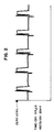
- Figs. 2 and 3 show the power delivered to the lamp at different duty factors during a lamp shutdown.
- the high level represents the amount of time the power is off (this is 240 nanoseconds for both cases) and the lower levels represent the period of time power is being delivered to the lamp.
- the on time is 690 nanoseconds and for Fig. 3 the on time is 96 nanoseconds.
- the lamp dims considerably in comparison to the continuous power operating mode.
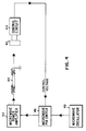
- FIG. 4 A block diagram of the system is shown in Fig. 4. This consists of a lamp 40, a photocell 42 to sense the light level, an electronic control circuit 44 which amplifies the photocell output and provides a DC voltage to a PIN diode switch 48, and the microwave power source or amplifier 50.
- the PIN diode switch 48 is placed between the microwave oscillator 49 and power amplifier 50.
- the output of the switch 48 is a sufficiently gradual function of the input control voltage to allow, it to function satisfactorily as an analog power control device.
- This switch is such that maximum power is supplied if a control voltage of -7 volts is applied. The power falls slowly at first as the control voltage is increased, then more rapidly as the control voltage exceeds -4 volts. The power becomes essentially zero above -2.5 volts.
- the lamp used in the experiments had a length of 10 mm, an outer diameter of 4 mm and an inner diameter of 3 mm.
- the mercury content within the lamp was 0.89 mg.
- the buffer gas within the lamp was neon at 20 torr pressure.
- .26 mg of NaScI4 was added to the fill which was comprised of a 12:1 molar ratio of NaI and ScI3. The dimensions and fill characteristics of the lamp affect its response to the electronic control circuit described below.
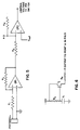
- the important features of the electronic control circuit can be understood with reference to Fig. 5.
- the output from the photocell is supplied to the inverting input of the operational amplifier OP1, with the non-inverting input connected to ground.
- the gain of this amplifier stage is determined by the ratio of resistors R2/R1.
- the output from this first stage is fed to the inverting input of a second stage of amplification OP2.
- the non-inverting input is connected to a negative reference potential -V ref .
- the gain of this second stage is the ratio R4/R3.
- the output from OP1 will be zero, while that from OP2 will be -V ref multiplied by (R4/R3). This is arranged to be about -7 volts.
- the light level is initially at its maximum value and is not under the control of this circuit.
- the circuit is put into control. Since it senses a high light level its output voltage rises to a positive value, thereby cutting off microwave power to the lamp. As the light level drops, the output voltage from the circuit becomes increasingly negative.
- the PIN diode switch allows microwave power to be re-applied to the lamp, which now is controlled at the desired light level.
- This light level which applies to the situation immediately after turn-off, is set as low as is practicable subject to constraints to be discussed later.
- a typical value is 10% of the continuous level before switch-off.
- the negative current supplied to point A is generated by the circuit shown in Fig. 6.
- This consists of a simple capacitor charging circuit with a time constant given by R5 and C1, which supplies a potential to the gate of the P-channel FET T1.
- This is operated as a source-follower with the output supplied through resistor R6 to point A in Fig. 5. Too rapid cooldown can result in lamp instability. A cooling time of about 2 minutes is adequate to ensure successful operation. Since the insulated gate of transistor T1 will store charge for long periods of time, it is necessary for the timer circuit to discharge this capacitor before subsequent use.
- Fig. 7(a) and 7(b) shows the short-term response of the control circuit.
- the upper trace (Fig. 7(a)) represents the microwave power applied to the lamp with zero at the top and power increasing in the downwards direction.
- the scale is in arbitrary units.
- the expanded scale shows that power is re-applied about 2.5 ms after turn-off in this case.
- the lower trace (Fig. 7(b)) represents the light level, which is brought under control at about 13% of the initial level after about 2.5 ms.
- the traces labeled a and b on each trace of Fig. 7(a) and (b) refer to the time scale used.
- Fig. 8(a) and 8(b) show the microwave power decreasing (Fig. 8(a)) and the light level decreasing (Fig.8(b)) over a period of two minutes, after which the lamp is in the glow state.
- Deionization time is defined here to be the maximum time that the microwave power may be removed while ensuring that the lamp will re-ignite when the power is re-applied. This is critical since, as explained previously, the circuit initially removes microwave power and then restores it when the light level has fallen to the predetermined value. However, the decay time of the light is not negligible and has a noticeable tail as the light is reduced to a low value. The consequence is that, for a given deionization time, the initial controllable light level after turn-off is limited to values such that the decay time is shorter.
- the deionization time is a function of the mercury pressure and chemical additives within the lamp, and of the effectiveness of the structure that couples microwave power into the lamp, in addition to the power level and frequency output of the power source. Typical times range from 0.5 ms to 3 ms.
- the decay time of the full spectrum of visible light is in the region of 2 ms.
- switch SW1 When the lamp is in its fully on state, switch SW1 is closed, which connects the PIN switch directly to -10 volts. Diode D1 protects the output of OP2 from this negative voltage. In this condition, transistors T3 and T5 are off, transistors T4 and T2 are on and resistor R2b is shorted.
- SW1 When the lamp is to be turned off, SW1 is opened and the lamp is placed under the control of the circuit. The output of OP2 swings positive, temporarily cutting off power to the lamp. Co-incident with this, transistor T3 is turned on. After a delay set by the time constant R8 multiplied by C2, T4 is turned off, T5 on and T2 off. This latter step inserts resistor R2b into the circuit and initiates the second stage of the light reduction as previously described.
Landscapes
- Circuit Arrangements For Discharge Lamps (AREA)
- Discharge Lamps And Accessories Thereof (AREA)
Applications Claiming Priority (2)
| Application Number | Priority Date | Filing Date | Title |
|---|---|---|---|
| US626365 | 1984-06-29 | ||
| US07/626,365 US5287039A (en) | 1990-12-12 | 1990-12-12 | Method of hot restarting electrodeless HID lamps |
Publications (3)
| Publication Number | Publication Date |
|---|---|
| EP0490647A2 true EP0490647A2 (fr) | 1992-06-17 |
| EP0490647A3 EP0490647A3 (en) | 1992-10-28 |
| EP0490647B1 EP0490647B1 (fr) | 1996-07-17 |
Family
ID=24510105
Family Applications (1)
| Application Number | Title | Priority Date | Filing Date |
|---|---|---|---|
| EP91311497A Expired - Lifetime EP0490647B1 (fr) | 1990-12-12 | 1991-12-11 | Méthode pour réamorcer à chaud des lampes à forte décharge sans électrodes |
Country Status (5)
| Country | Link |
|---|---|
| US (1) | US5287039A (fr) |
| EP (1) | EP0490647B1 (fr) |
| JP (1) | JPH04277496A (fr) |
| CA (1) | CA2056225C (fr) |
| DE (1) | DE69120911T2 (fr) |
Cited By (5)
| Publication number | Priority date | Publication date | Assignee | Title |
|---|---|---|---|---|
| EP0595398A2 (fr) * | 1992-10-26 | 1994-05-04 | Koninklijke Philips Electronics N.V. | Lampe à décharge à haute pression dotée d'une protection fusille de surintensité |
| EP0794693A1 (fr) * | 1996-03-08 | 1997-09-10 | Fusion Systems Corporation | Alimentation pour magnétron permettant le redéclenchement vite d'une lampe sansélectrodes |
| GB2319406A (en) * | 1996-11-12 | 1998-05-20 | Uvp Inc | Dimming a medium pressure arc lamp; UV lamp standby mode |
| US8029151B2 (en) | 2008-03-27 | 2011-10-04 | Abl Ip Holding Llc | Back-up lighting system |
| US8845152B2 (en) | 2011-09-28 | 2014-09-30 | Abl Ip Holding Llc | Pole mounted enclosures for luminaires |
Families Citing this family (5)
| Publication number | Priority date | Publication date | Assignee | Title |
|---|---|---|---|---|
| US5373217A (en) * | 1993-03-24 | 1994-12-13 | Osram Sylvania Inc. | Method and circuit for enhancing stability during dimming of electrodeless hid lamp |
| US5723951A (en) * | 1996-06-26 | 1998-03-03 | Osram Sylvania Inc. | Method of hot restarting a high intensity discharge lamp |
| US5990627A (en) * | 1996-10-10 | 1999-11-23 | Osram Sylvania, Inc. | Hot relight system for electrodeless high intensity discharge lamps |
| EP1336326A4 (fr) | 2000-11-22 | 2004-04-14 | Fusion Uv Sys Inc | Alimentation electrique de lampe a ultraviolet et procede de fonctionnement a un niveau de puissance elevee/refroidissement reduit par etablissement de cycle |
| US6583588B2 (en) * | 2001-05-29 | 2003-06-24 | Koninklijke Philips Electronics N.V. | System and method of automatic cycling control for HID lamps |
Family Cites Families (8)
| Publication number | Priority date | Publication date | Assignee | Title |
|---|---|---|---|---|
| US4219760A (en) * | 1979-03-22 | 1980-08-26 | General Electric Company | SEF Lamp dimming |
| US4320325A (en) * | 1979-04-12 | 1982-03-16 | General Electric Company | Circuit for starting and ballasting arc discharge lamps |
| US4383203A (en) * | 1981-06-29 | 1983-05-10 | Litek International Inc. | Circuit means for efficiently driving an electrodeless discharge lamp |
| US4456891A (en) * | 1981-07-20 | 1984-06-26 | Rockwell International Corporation | Radio frequency source circuit primarily for igniting the lamp of a rubidium frequency standard |
| US4451765A (en) * | 1982-05-24 | 1984-05-29 | Moniteq Ltd. | Resonance lamp |
| US4631449A (en) * | 1984-08-06 | 1986-12-23 | General Electric Company | Integral crystal-controlled line-voltage ballast for compact RF fluorescent lamps |
| US4751434A (en) * | 1986-07-28 | 1988-06-14 | Helling James C | Self-illuminated sealed cool light display and method |
| US4739227A (en) * | 1986-09-26 | 1988-04-19 | General Electric Company | Fluorescent lamp dimming over large light output range |
-
1990
- 1990-12-12 US US07/626,365 patent/US5287039A/en not_active Expired - Lifetime
-
1991
- 1991-11-26 CA CA002056225A patent/CA2056225C/fr not_active Expired - Fee Related
- 1991-12-06 JP JP3348641A patent/JPH04277496A/ja not_active Withdrawn
- 1991-12-11 DE DE69120911T patent/DE69120911T2/de not_active Expired - Lifetime
- 1991-12-11 EP EP91311497A patent/EP0490647B1/fr not_active Expired - Lifetime
Cited By (5)
| Publication number | Priority date | Publication date | Assignee | Title |
|---|---|---|---|---|
| EP0595398A2 (fr) * | 1992-10-26 | 1994-05-04 | Koninklijke Philips Electronics N.V. | Lampe à décharge à haute pression dotée d'une protection fusille de surintensité |
| EP0794693A1 (fr) * | 1996-03-08 | 1997-09-10 | Fusion Systems Corporation | Alimentation pour magnétron permettant le redéclenchement vite d'une lampe sansélectrodes |
| GB2319406A (en) * | 1996-11-12 | 1998-05-20 | Uvp Inc | Dimming a medium pressure arc lamp; UV lamp standby mode |
| US8029151B2 (en) | 2008-03-27 | 2011-10-04 | Abl Ip Holding Llc | Back-up lighting system |
| US8845152B2 (en) | 2011-09-28 | 2014-09-30 | Abl Ip Holding Llc | Pole mounted enclosures for luminaires |
Also Published As
| Publication number | Publication date |
|---|---|
| EP0490647A3 (en) | 1992-10-28 |
| CA2056225A1 (fr) | 1992-06-13 |
| JPH04277496A (ja) | 1992-10-02 |
| CA2056225C (fr) | 2002-06-04 |
| US5287039A (en) | 1994-02-15 |
| EP0490647B1 (fr) | 1996-07-17 |
| DE69120911D1 (de) | 1996-08-22 |
| DE69120911T2 (de) | 1997-01-30 |
Similar Documents
| Publication | Publication Date | Title |
|---|---|---|
| US6075326A (en) | High intensity discharge lamp ballast and lighting system | |
| EP1209955B1 (fr) | Circuit pour l' éclairage par l' arrière d' un afficheur LCD | |
| CA1284171C (fr) | Circuit d'amorcages a froid et a chaud et d'alimentation pour une lampe | |
| US4529912A (en) | Mechanism and method for controlling the temperature and light output of a fluorescent lamp | |
| US5287039A (en) | Method of hot restarting electrodeless HID lamps | |
| WO1996020578A3 (fr) | Procede d'allumage et de fonctionnement d'une lampe a decharge a haute pression et circuit permettant d'utiliser ce procede | |
| KR940702677A (ko) | 전원 회로(Power supply circuit) | |
| EP0327537A1 (fr) | Ballast pour lampes au sodium haute pression ayant une puissance en watts secteur et lampe constante | |
| US6791281B2 (en) | High pressure discharge lamp lighting apparatus and luminaire using thereof | |
| US5373217A (en) | Method and circuit for enhancing stability during dimming of electrodeless hid lamp | |
| JP2000287035A (ja) | 光源制御装置 | |
| PL342398A1 (en) | Method of and apparatus for controlling operation of electronic ballasts for hid discharge lamps | |
| CA2208857C (fr) | Methode de reamorcage a chaud d'une lampe a decharge haute intensite | |
| JPH06243978A (ja) | 自動起動ランプ装置 | |
| US7919933B2 (en) | High intensity discharge strobe light | |
| JP3411542B2 (ja) | 高圧放電ランプの点灯方法及び点灯装置 | |
| JP2007094266A (ja) | 表示装置用の放電管点灯装置 | |
| US6285136B1 (en) | Lighting driver for discharge lamp | |
| JP2842489B2 (ja) | 高圧放電灯点灯装置 | |
| JPH07176391A (ja) | 放電ランプ点灯方法 | |
| ATE159141T1 (de) | Vorschaltgerät zum starten und betreiben von hochdruck-gasentladungslampen | |
| JP3510550B2 (ja) | 圧電トランス駆動回路 | |
| KR100499331B1 (ko) | 형광등용 전자식안정기의 저조도 점등제어장치 및 점등제어방법 | |
| JPH0696891A (ja) | 放電灯点灯装置 | |
| JP4134611B2 (ja) | 高圧放電ランプ点灯装置 |
Legal Events
| Date | Code | Title | Description |
|---|---|---|---|
| PUAI | Public reference made under article 153(3) epc to a published international application that has entered the european phase |
Free format text: ORIGINAL CODE: 0009012 |
|
| AK | Designated contracting states |
Kind code of ref document: A2 Designated state(s): DE FR GB IT NL SE |
|
| RAP1 | Party data changed (applicant data changed or rights of an application transferred) |
Owner name: GTE PRODUCTS CORPORATION |
|
| PUAL | Search report despatched |
Free format text: ORIGINAL CODE: 0009013 |
|
| AK | Designated contracting states |
Kind code of ref document: A3 Designated state(s): DE FR GB IT NL SE |
|
| 17P | Request for examination filed |
Effective date: 19930415 |
|
| 17Q | First examination report despatched |
Effective date: 19941201 |
|
| GRAH | Despatch of communication of intention to grant a patent |
Free format text: ORIGINAL CODE: EPIDOS IGRA |
|
| GRAH | Despatch of communication of intention to grant a patent |
Free format text: ORIGINAL CODE: EPIDOS IGRA |
|
| GRAA | (expected) grant |
Free format text: ORIGINAL CODE: 0009210 |
|
| AK | Designated contracting states |
Kind code of ref document: B1 Designated state(s): DE FR GB IT NL SE |
|
| ET | Fr: translation filed | ||
| REF | Corresponds to: |
Ref document number: 69120911 Country of ref document: DE Date of ref document: 19960822 |
|
| ITF | It: translation for a ep patent filed | ||
| PG25 | Lapsed in a contracting state [announced via postgrant information from national office to epo] |
Ref country code: SE Effective date: 19961017 |
|
| PLBQ | Unpublished change to opponent data |
Free format text: ORIGINAL CODE: EPIDOS OPPO |
|
| PLBI | Opposition filed |
Free format text: ORIGINAL CODE: 0009260 |
|
| PLBF | Reply of patent proprietor to notice(s) of opposition |
Free format text: ORIGINAL CODE: EPIDOS OBSO |
|
| 26 | Opposition filed |
Opponent name: FUSION UV SYSTEMS INC. Effective date: 19970416 |
|
| NLR1 | Nl: opposition has been filed with the epo |
Opponent name: FUSION UV SYSTEMS INC. |
|
| PLBF | Reply of patent proprietor to notice(s) of opposition |
Free format text: ORIGINAL CODE: EPIDOS OBSO |
|
| PLBF | Reply of patent proprietor to notice(s) of opposition |
Free format text: ORIGINAL CODE: EPIDOS OBSO |
|
| RDAH | Patent revoked |
Free format text: ORIGINAL CODE: EPIDOS REVO |
|
| APAC | Appeal dossier modified |
Free format text: ORIGINAL CODE: EPIDOS NOAPO |
|
| APAE | Appeal reference modified |
Free format text: ORIGINAL CODE: EPIDOS REFNO |
|
| APAC | Appeal dossier modified |
Free format text: ORIGINAL CODE: EPIDOS NOAPO |
|
| APAC | Appeal dossier modified |
Free format text: ORIGINAL CODE: EPIDOS NOAPO |
|
| REG | Reference to a national code |
Ref country code: GB Ref legal event code: IF02 |
|
| PLBQ | Unpublished change to opponent data |
Free format text: ORIGINAL CODE: EPIDOS OPPO |
|
| PLAB | Opposition data, opponent's data or that of the opponent's representative modified |
Free format text: ORIGINAL CODE: 0009299OPPO |
|
| R26 | Opposition filed (corrected) |
Opponent name: FUSION UV SYSTEMS INC. Effective date: 19970416 |
|
| PLBP | Opposition withdrawn |
Free format text: ORIGINAL CODE: 0009264 |
|
| PLBD | Termination of opposition procedure: decision despatched |
Free format text: ORIGINAL CODE: EPIDOSNOPC1 |
|
| PLBM | Termination of opposition procedure: date of legal effect published |
Free format text: ORIGINAL CODE: 0009276 |
|
| STAA | Information on the status of an ep patent application or granted ep patent |
Free format text: STATUS: OPPOSITION PROCEDURE CLOSED |
|
| 27C | Opposition proceedings terminated |
Effective date: 20041204 |
|
| NLR2 | Nl: decision of opposition |
Effective date: 20041204 |
|
| APAH | Appeal reference modified |
Free format text: ORIGINAL CODE: EPIDOSCREFNO |
|
| PGFP | Annual fee paid to national office [announced via postgrant information from national office to epo] |
Ref country code: FR Payment date: 20101230 Year of fee payment: 20 |
|
| PGFP | Annual fee paid to national office [announced via postgrant information from national office to epo] |
Ref country code: GB Payment date: 20101209 Year of fee payment: 20 Ref country code: NL Payment date: 20101203 Year of fee payment: 20 |
|
| PGFP | Annual fee paid to national office [announced via postgrant information from national office to epo] |
Ref country code: IT Payment date: 20101229 Year of fee payment: 20 Ref country code: DE Payment date: 20110221 Year of fee payment: 20 |
|
| REG | Reference to a national code |
Ref country code: DE Ref legal event code: R071 Ref document number: 69120911 Country of ref document: DE |
|
| REG | Reference to a national code |
Ref country code: DE Ref legal event code: R071 Ref document number: 69120911 Country of ref document: DE |
|
| REG | Reference to a national code |
Ref country code: GB Ref legal event code: PE20 Expiry date: 20111210 |
|
| PG25 | Lapsed in a contracting state [announced via postgrant information from national office to epo] |
Ref country code: GB Free format text: LAPSE BECAUSE OF EXPIRATION OF PROTECTION Effective date: 20111210 |
|
| REG | Reference to a national code |
Ref country code: NL Ref legal event code: V4 Effective date: 20111211 |
|
| PG25 | Lapsed in a contracting state [announced via postgrant information from national office to epo] |
Ref country code: DE Free format text: LAPSE BECAUSE OF EXPIRATION OF PROTECTION Effective date: 20111212 |