EP0490743A2 - Verfahren zum Steuern der Metalloxyd-Rauchentwicklung während der sauerstoffinduzierten Aufteilung eines Körpers, der Metallbestandteile enthält - Google Patents
Verfahren zum Steuern der Metalloxyd-Rauchentwicklung während der sauerstoffinduzierten Aufteilung eines Körpers, der Metallbestandteile enthält Download PDFInfo
- Publication number
- EP0490743A2 EP0490743A2 EP91403313A EP91403313A EP0490743A2 EP 0490743 A2 EP0490743 A2 EP 0490743A2 EP 91403313 A EP91403313 A EP 91403313A EP 91403313 A EP91403313 A EP 91403313A EP 0490743 A2 EP0490743 A2 EP 0490743A2
- Authority
- EP
- European Patent Office
- Prior art keywords
- oxygen
- carbon dioxide
- accordance
- gas
- subdivision
- Prior art date
- Legal status (The legal status is an assumption and is not a legal conclusion. Google has not performed a legal analysis and makes no representation as to the accuracy of the status listed.)
- Granted
Links
Images


Classifications
-
- C—CHEMISTRY; METALLURGY
- C21—METALLURGY OF IRON
- C21C—PROCESSING OF PIG-IRON, e.g. REFINING, MANUFACTURE OF WROUGHT-IRON OR STEEL; TREATMENT IN MOLTEN STATE OF FERROUS ALLOYS
- C21C5/00—Manufacture of carbon-steel, e.g. plain mild steel, medium carbon steel or cast steel or stainless steel
- C21C5/28—Manufacture of steel in the converter
- C21C5/38—Removal of waste gases or dust
-
- C—CHEMISTRY; METALLURGY
- C21—METALLURGY OF IRON
- C21B—MANUFACTURE OF IRON OR STEEL
- C21B3/00—General features in the manufacture of pig-iron
- C21B3/04—Recovery of by-products, e.g. slag
-
- C—CHEMISTRY; METALLURGY
- C22—METALLURGY; FERROUS OR NON-FERROUS ALLOYS; TREATMENT OF ALLOYS OR NON-FERROUS METALS
- C22B—PRODUCTION AND REFINING OF METALS; PRETREATMENT OF RAW MATERIALS
- C22B1/00—Preliminary treatment of ores or scrap
- C22B1/005—Preliminary treatment of scrap
-
- Y—GENERAL TAGGING OF NEW TECHNOLOGICAL DEVELOPMENTS; GENERAL TAGGING OF CROSS-SECTIONAL TECHNOLOGIES SPANNING OVER SEVERAL SECTIONS OF THE IPC; TECHNICAL SUBJECTS COVERED BY FORMER USPC CROSS-REFERENCE ART COLLECTIONS [XRACs] AND DIGESTS
- Y02—TECHNOLOGIES OR APPLICATIONS FOR MITIGATION OR ADAPTATION AGAINST CLIMATE CHANGE
- Y02P—CLIMATE CHANGE MITIGATION TECHNOLOGIES IN THE PRODUCTION OR PROCESSING OF GOODS
- Y02P10/00—Technologies related to metal processing
- Y02P10/20—Recycling
-
- Y—GENERAL TAGGING OF NEW TECHNOLOGICAL DEVELOPMENTS; GENERAL TAGGING OF CROSS-SECTIONAL TECHNOLOGIES SPANNING OVER SEVERAL SECTIONS OF THE IPC; TECHNICAL SUBJECTS COVERED BY FORMER USPC CROSS-REFERENCE ART COLLECTIONS [XRACs] AND DIGESTS
- Y02—TECHNOLOGIES OR APPLICATIONS FOR MITIGATION OR ADAPTATION AGAINST CLIMATE CHANGE
- Y02W—CLIMATE CHANGE MITIGATION TECHNOLOGIES RELATED TO WASTEWATER TREATMENT OR WASTE MANAGEMENT
- Y02W30/00—Technologies for solid waste management
- Y02W30/50—Reuse, recycling or recovery technologies
Definitions
- the present invention relates to a process and an apparatus for controlling metal oxide fume generation during the oxygen-induced subdivision of a body containing metal values, such as slag and/or scrap.
- Slag is a common by-product of metal refining. All steelmaking processes including open-hearth, basic oxygen, electric arc furnace, argon-oxygen decarburization and other processes produce slag in their respective refining processes. Other metallic refining processes such as aluminum smelting, copper smelting and blast furnace processes produce slag. Metal refining is a means of separating a particular desired metal from the undesirable or waste product (in the form of slag.)
- metal refiners have the option of recovering these metallics and they may then be used as part of an overall total metallic charge for a particular refining process.
- slag pot designs vary, their shapes are basically similar. Electric furnace slag pots look much the same as basic oxygen slag pots. Argon-oxygen decarburization slag pots (depending on the size of the furnace) are generally smaller than most basic oxygen furnace slag pots. Hence, many argonoxygen decarburization facilities spray a silicon coating on the walls of their slag pots rather than put sand in the bottom. The resulting shape of AOD slag is conical rather than that of a button. Aluminum and copper slags are skimmed from the bath and placed in a dross bucket. For the sake of simplicity, slag is in referred to in the forthcoming description of the present invention as being in the shape of a button.
- slag After slag has been loaded into a slag pot, it is usually transported outside of the furnace building to a slag preparation area. This area is commonly referred to as the "slag pits".
- the slag buttons are transported to the slag pits and dumped.
- furnace slag the slag is crushed, screened and magnetically separated according to its metallic content. Slag high in metallic content is charged back to the steelmaking furnace for iron recovery. Processed slag which does not meet the mills' criteria for contained iron is subsequently sold as construction aggregate. Buttons are frequently too thick to be broken with a drop ball. In order to prepare this large mass of ladle remains for the crusher, the button must be sectioned by a fuel gas torch while still warm.
- buttons fresh out of the mill are extremely hot and usually molten in the center. Most slag burning is preferred to be done on buttons that are still warm since it requires less fuel to cut the button into sections.
- a typical button may range in thickness from four to eight feet and weigh up to 40 tons.
- This setup is characteristic of many slag preparation operations.
- revert scrap as billets or finished mill product are also burned with oxygen and fuel gas torches.
- the scrap is torch cut into appropriate lengths, usually two to four feet long, for charging in the electric arc or basic oxygen furnace.
- Large mill torches such as the Victor HC-1500C Scrap Torch, utilize natural gas or propane as fuel gas.
- Oxygen is subsequently introduced at high flowrates to cut or oxidize the metal by self-sustaining exothermic reactions. Oxygen flowrates from 50 to 80 standard cubic feet per minute at 75 to 150 pounds per square inch (gauge) are common for mill torches.
- a method for controlling metal oxide fume generation during the oxygen-induced subdivision into smaller physical units of a body containing metal values comprising the steps of:
- an apparatus for the oxygen-induced subdivision into smaller physical units of a body containing metal values which decreasing metal oxide fume generation during said oxygen-induced subdivision, comprising means for subdividing said body with gaseous oxygen in a control gas-enriched, oxygen environment in the absence of a fuel gas, including a source of gas consisting essentially of oxygen and a control gas and a consumable lance member operatively connected to said source gas.
- the preferred method comprises a) providing a body containing metal values and b) subdividing that body with a consumable lance using gaseous oxygen in a carbon dioxide-enriched, oxygen environment in the absence of a fuel gas.
- the preferred apparatus comprises means for subdividing the body with gaseous oxygen in a carbon dioxide-enriched, oxygen environment in the absence of a fuel gas, including a consumable lance member operatively connected to source means of gas consisting essentially of oxygen and carbon dioxide.
- the method and apparatus of the present invention can be used to increase metal fume generation during the oxygen-induced subdivision of a body containing metal values into smaller physical units by replacing the carbon dioxide with nitrogen or an inert gas selected from Group 8 of the periodic Table.
- a body containing metal values such as a slag button or scrap, is subdivided by cutting or lancing with a consumable lance using gaseous oxygen in a carbon dioxide-enriched oxygen environment in the absence of a fuel gas.
- the consumable lance is a cutting lance which is provided with an outlet pipe which is consumed in a highly exothermic reaction with the gaseous oxygen.
- Desirable consumable materials for use in connection with bodies having iron as their primary desired metal values are iron and steel, preferably steel.
- Slag buttons are sectioned into "slices" using oxygen of standard purity (99.5%) through a consumable lance pipe.
- Button size and their number generally determine the size and flow rate of the lancing apparatus.
- the oxygen lance pipe generally ranges from 3/8 to 1-1/4 inches in diameter for button burning.
- Oxygen flowrates from 60 to 150 standard cubic feet per minute at 120 to 150 pounds per square inch (gauge) are generally used in this application. For instance, if a basic oxygen furnace generates 20 ton buttons (8′ dia. x 4′ thick), the following lancing apparatus is typical:
- Carbon dioxide enrichment may be provided to the gaseous oxygen environment in which subdivision occurs by
- Slag high in metallic content primarily FeO
- metallic content is less in higher lime-bearing slag
- the operator must reduce the ratio of CO2 in oxygen.
- the reduction of carbon dioxide at the lance does not change the effect of the process in regards to fume suppression.
- the initiation of a torch path while carbon dioxide is flowing hinders the burning path initiation. Therefore, the best method of initiating burning results is with straight gaseous oxygen (i.e. with carbon dioxide flow off or not present) to get the bum started. Consequently, an initial slag puddle using pure oxygen only is established before introduction of the oxygen and carbon dioxide mixture. During the time a slag puddle is initiated, the typical orange vapor is visible.
- carbon dioxide is added in ratio to the gaseous oxygen and adjusted to the appropriate rate and pressure with respect to the oxygen flow rate and pressure, slag chemistry and button temperature.
- the orange plume quickly disappears and is replaced by a clear, lightly yellow vapor.
- the lance operator continues the cutting action until the button is sectioned. The same procedure is used until the entire button is small enough for recharge to the furnace.
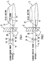
- a button 1 may be cut or burned into smaller pieces by a consumable oxygen lance 10 whose distal end 12 is consumed by the oxygen passing through it to supply the necessary heat energy to melt or burn the button 1 .
- the lance 10 is supplied at its proximal end 14 with gaseous oxygen from a suitable source.
- a valve 15 is provided to control the flow as necessary.
- a carbon dioxide-enriched, oxygen environment may be provided by supplying solid particles of carbon dioxide or carbon dioxide "snow" to the zone in which the subdivision (cutting or melting or burning)is occurring.
- a carbon dioxide snow conduit 20 is provided whose distal end 22 comprises a horn 23 from which the carbon dioxide snow is ejected into the subdivision zone.
- the horn 23 facilitates dispersion of the carbon dioxide.
- the proximal end 24 of the conduit 20 is supplied with carbon dioxide snow from a suitable source.
- Valve 26 is provided to control the flow of carbon dioxide snow and to shut off that flow as necessary.
- the operator may be protected by a suitable shield interposed between the operator and the distal end 12 of the lance 10 .
- the various elements perform as in the embodiment of Fig. 2, except that the carbon dioxide conduit 20 is supplied with gaseous carbon dioxide at its proximal end 24 and that gaseous carbon dioxide is controlled by valve 26 and dispensed as gaseous carbon dioxide to the subdivision zone by distal end 22.
- gaseous oxygen and gaseous carbon dioxide are supplied to proximal ends 14 and 24, respectively, and controlled by valves 16 and 26, respectively, as in the embodiment of Fig. 3.
- a mixing chamber 30 is provided for receiving the and mixing gaseous oxygen and gaseous carbon dioxide flows and providing carbon dioxide-enriched, oxygen flow as its output.
- the carbon dioxide-enriched oxygen flows from mixing chamber 30 down a consumable lance member 18 to distal end 12′.
- FIG. 5 illustrates on embodiment of a mixing chamber 30 for use with the present invention.
- gaseous oxygen conduit 32 has a gaseous carbon dioxide conduit 34 circumferentially enclosing its distal end 33 and coaxially aligned with it.
- Gaseous oxygen enters the proximal end 33A of the oxygen conduit 32 and is dispensed to the interior of the mixing chamber 30 by the distal end 33 of the conduit 32.
- Gaseous carbon dioxide enters the mixing chamber 30 through an inlet conduit 36 extending out from the mixing chamber 30 in a radial direction with respect to the longitudinal central axis of the chamber 30 and the oxygen and carbon dioxide conduits 32 and 34, respectively.
- the distal end 33, or exit, of the oxygen conduit 32 is disposed downstream of the carbon dioxide inlet 36 with respect to the flow of gas through the chamber.
- Figure 6 illustrates a further embodiment of a mixing chamber 30 for use with the present invention.
- the gaseous oxygen inlet 38 and the carbon dioxide-enriched environment exit 39 are the axially aligned legs of a Y-shaped connector while the longitudinal central axis of the carbon dioxide inlet 40 intersects the longitudinal central axis common to the oxygen inlet 38 and the carbon dioxide-enriched, oxygen environment outlet 39 at an acute angle.
- the longitudinal central axis of the carbon dioxide inlet 40 intersects the longitudinal axis common to the oxygen inlet 38 and the carbon dioxide-enriched environment outlet 39 radially, i.e., at an appropriate right angle.
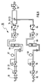
- FIG 8 schematically illustrates a preferred embodiment of a mixing means 50 for use with the present invention.
- oxygen carbon-dioxide are supplied from respective sources (not shown) to a pitot tube-type mixing chamber 70 .
- the oxygen gas supply is connected to the mixing means 50 through a union 51 for ready connection and disconnection. It then passes through a control valve 53 for controlling its flow and then pressure regulator 55 for regulating its pressure. After regulation oxygen pressure is monitored by a pressure gauge 57 and them its flow rate by a flowemeter 59.
- a shutoff 61 permits complete shutoff of oxygen flow.
- a check valve 63 downstream prevents backflow of gases into the oxygen lines.
- the carbon dioxide gas handling is similar to that for oxygen.
- the carbon dioxide gas supply is connected to the mixing means 50 through union 52. It then passes through control valve 54 to control its flow and pressure regulator 56 to regulate its pressure. Then the carbon dioxide gas pressure is monitored by pressure gauge 58 and them its flow rate by flow meter 60.
- the shutoff valve 62 downstream of the flowmeter 59 permits complete shutoff of carbon dioxide gas flow.
- the check valve 64 downstream of the shutoff valve prevents backflow of gases into the carbon dioxide gas lines.
- Supply of oxygen gas and carbon dioxide gas to the mixing means 50 is desirably at a pressure of about 100 to about 150 pounds per square inch (gauge).
- the pressure regulators 55 and 56 desirably reduce this pressure to about 75 to about 100 pounds per square inch gauge. It is desirable to maintain a carbon-dioxide gas pressure at the nozzle outlet 72 which is generally equal to the oxygen gas pressure at the inlet tube 74 to avoid backflow of oxygen gas into the carbon dioxide line.
- Offgas emission samples generated during the traditional practice of oxygen cutting of slag typically generate the following analysis:
- the method and apparatus of the present invention are also adopted for cutting scrap. While fuel gas and oxygen are used to start a molten puddle before the addition of carbon dioxide, the cutting proceeds without the use of fuel gas.
- the cutting torch or lance is provided with two oxygen lines.
- the oxygen line for fuel gas does not employ carbon dioxide.
- a large oxygen line for cutting is premixed with carbon dioxide for fume suppression.
- the vapor indicative of scrap cutting is primarily a thick yellow fume. By adding carbon dioxide in small percentages to the cutting oxygen, the yellow smoke virtually disappears and is replaced by a clear, lightly white fume.
- metal oxide fume generation While it is preferred to decrease the generation of metal oxide fumes, under certain circumstances it may be desirable to increase metal oxide fume generation. It has been found that if nitrogen or an inert gas selected from Group 8 of the Periodic Table is substituted instead of carbon dioxide, then metal oxide fume generation is increased. This is particularly surprising since it is a result contrary to Fick's law.
Landscapes
- Engineering & Computer Science (AREA)
- Chemical & Material Sciences (AREA)
- Organic Chemistry (AREA)
- Metallurgy (AREA)
- Materials Engineering (AREA)
- Manufacturing & Machinery (AREA)
- Environmental & Geological Engineering (AREA)
- Geology (AREA)
- Life Sciences & Earth Sciences (AREA)
- Mechanical Engineering (AREA)
- Geochemistry & Mineralogy (AREA)
- General Life Sciences & Earth Sciences (AREA)
- Carbon Steel Or Casting Steel Manufacturing (AREA)
- Manufacture And Refinement Of Metals (AREA)
- Catalysts (AREA)
- Pharmaceuticals Containing Other Organic And Inorganic Compounds (AREA)
- Processing Of Solid Wastes (AREA)
Applications Claiming Priority (2)
| Application Number | Priority Date | Filing Date | Title |
|---|---|---|---|
| US07/626,207 US5196072A (en) | 1990-12-12 | 1990-12-12 | Method and apparatus for controlling metal oxide fume generation during subdivision of a body containing metal values |
| US626207 | 1996-03-29 |
Publications (3)
| Publication Number | Publication Date |
|---|---|
| EP0490743A2 true EP0490743A2 (de) | 1992-06-17 |
| EP0490743A3 EP0490743A3 (en) | 1993-01-20 |
| EP0490743B1 EP0490743B1 (de) | 1997-01-22 |
Family
ID=24509407
Family Applications (1)
| Application Number | Title | Priority Date | Filing Date |
|---|---|---|---|
| EP19910403313 Expired - Lifetime EP0490743B1 (de) | 1990-12-12 | 1991-12-09 | Verfahren zum Steuern der Metalloxyd-Rauchentwicklung während der sauerstoffinduzierten Aufteilung eines Körpers, der Metallbestandteile enthält |
Country Status (7)
| Country | Link |
|---|---|
| US (1) | US5196072A (de) |
| EP (1) | EP0490743B1 (de) |
| JP (1) | JPH059514A (de) |
| AU (1) | AU641575B2 (de) |
| CA (1) | CA2057457A1 (de) |
| DE (1) | DE69124350T2 (de) |
| ES (1) | ES2099146T3 (de) |
Families Citing this family (4)
| Publication number | Priority date | Publication date | Assignee | Title |
|---|---|---|---|---|
| US6460742B1 (en) | 1989-02-14 | 2002-10-08 | L'air Liquide Societe Anonyme Pour L'etude Et L'exploitation Des Procedes Georges Claude | Process for reducing fume emissions during molten metal transfer |
| US6228187B1 (en) | 1998-08-19 | 2001-05-08 | Air Liquide America Corp. | Apparatus and methods for generating an artificial atmosphere for the heat treating of materials |
| US6491863B2 (en) | 2000-12-12 | 2002-12-10 | L'air Liquide-Societe' Anonyme A' Directoire Et Conseil De Surveillance Pour L'etude Et L'exploitation Des Procedes George Claude | Method and apparatus for efficient utilization of a cryogen for inert cover in metals melting furnaces |
| US20230250954A1 (en) * | 2022-02-04 | 2023-08-10 | Total Combustion IP Holdings, LLC | Oxygen torch cutting system |
Family Cites Families (5)
| Publication number | Priority date | Publication date | Assignee | Title |
|---|---|---|---|---|
| AT185831B (de) * | 1951-06-15 | 1956-06-11 | Westfalenhuette Ag | Verfahren zur Vorfrischen von Roheisen oder Stahleisen in der Pfanne |
| AU500974B2 (en) * | 1976-01-12 | 1979-06-07 | Ee Fassler | Thermal lance |
| GB2050223A (en) * | 1978-10-10 | 1981-01-07 | Heather Chemicals Ltd | Method of and apparatus for cutting |
| DE3904415C1 (de) * | 1989-02-14 | 1990-04-26 | Intracon Handelsgesellschaft Fuer Industriebedarf M.B.H., 6200 Wiesbaden, De | |
| US5000426A (en) * | 1989-08-15 | 1991-03-19 | Edna Corporation | Exothermic cutting torch |
-
1990
- 1990-12-12 US US07/626,207 patent/US5196072A/en not_active Expired - Fee Related
-
1991
- 1991-12-09 DE DE69124350T patent/DE69124350T2/de not_active Expired - Fee Related
- 1991-12-09 AU AU88909/91A patent/AU641575B2/en not_active Ceased
- 1991-12-09 EP EP19910403313 patent/EP0490743B1/de not_active Expired - Lifetime
- 1991-12-09 ES ES91403313T patent/ES2099146T3/es not_active Expired - Lifetime
- 1991-12-10 JP JP3325970A patent/JPH059514A/ja active Pending
- 1991-12-10 CA CA 2057457 patent/CA2057457A1/en not_active Abandoned
Also Published As
| Publication number | Publication date |
|---|---|
| CA2057457A1 (en) | 1992-06-13 |
| JPH059514A (ja) | 1993-01-19 |
| DE69124350D1 (de) | 1997-03-06 |
| AU8890991A (en) | 1992-06-18 |
| EP0490743B1 (de) | 1997-01-22 |
| US5196072A (en) | 1993-03-23 |
| ES2099146T3 (es) | 1997-05-16 |
| AU641575B2 (en) | 1993-09-23 |
| EP0490743A3 (en) | 1993-01-20 |
| DE69124350T2 (de) | 1997-08-21 |
Similar Documents
| Publication | Publication Date | Title |
|---|---|---|
| AU2009236006B2 (en) | Refining ferroalloys | |
| US4456476A (en) | Continuous steelmaking and casting | |
| KR20000068375A (ko) | 용융금속을 생산하는 설비 및 방법 | |
| US4615511A (en) | Continuous steelmaking and casting | |
| US3672870A (en) | Spray refining | |
| JPS6294792A (ja) | 製鋼炉用装入原料の連続予熱方法および装置 | |
| EP0012537B1 (de) | Wassergekühlte Lanze und deren Verwendung bei metallurgischen Aufblasverfahren | |
| US5196072A (en) | Method and apparatus for controlling metal oxide fume generation during subdivision of a body containing metal values | |
| US2669511A (en) | Method for refining ferrous metals | |
| EP0134336A1 (de) | Verfahren zum kontinuierlichen Erzeugen und Vergiessen von Stahl | |
| US4544405A (en) | Method of producing steels of great purity and low gas content in steel mills and steel foundries and apparatus therefor | |
| RU2380633C1 (ru) | Дуплекс-печь для выплавки марганцевых сплавов из железомарганцевых бедных руд и концентратов и техногенных отходов металлургии | |
| US3695863A (en) | Steelmaking | |
| RU2649476C2 (ru) | Способ выплавки стали в агрегате печь-ковш | |
| EP1190104A1 (de) | Verfahren zur entkohlung und entphosphorung einer metallschmelze | |
| JP2747524B2 (ja) | プラズマ燃焼式キュポラ内の原料の脱硫方法 | |
| US11466332B2 (en) | Process for injecting particulate material into a liquid metal bath | |
| RU2285726C1 (ru) | Способ выплавки стали в подовом сталеплавильном агрегате | |
| SU729251A1 (ru) | Способ выплавки стали в подовом сталеплавильном агрегате | |
| GB2138556A (en) | Apparatus for Burning Fuel and Feeding the Products of Combustion Into a Melt | |
| JPH11256217A (ja) | 転炉の副原料の供給方法 | |
| JP2549622B2 (ja) | 屑鉄溶解用バ−ナ−ランス | |
| McFeaters | The reaction of nitrogen with liquid steel in a plasma induction reactor | |
| JPS6169943A (ja) | フエロクロムの溶融還元方法 | |
| WO1998049353A2 (en) | Method for melting steel in a converter |
Legal Events
| Date | Code | Title | Description |
|---|---|---|---|
| PUAI | Public reference made under article 153(3) epc to a published international application that has entered the european phase |
Free format text: ORIGINAL CODE: 0009012 |
|
| 17P | Request for examination filed |
Effective date: 19911212 |
|
| AK | Designated contracting states |
Kind code of ref document: A2 Designated state(s): CH DE ES FR IT LI LU NL SE |
|
| PUAL | Search report despatched |
Free format text: ORIGINAL CODE: 0009013 |
|
| AK | Designated contracting states |
Kind code of ref document: A3 Designated state(s): CH DE ES FR IT LI LU NL SE |
|
| 17Q | First examination report despatched |
Effective date: 19950309 |
|
| GRAG | Despatch of communication of intention to grant |
Free format text: ORIGINAL CODE: EPIDOS AGRA |
|
| GRAH | Despatch of communication of intention to grant a patent |
Free format text: ORIGINAL CODE: EPIDOS IGRA |
|
| GRAH | Despatch of communication of intention to grant a patent |
Free format text: ORIGINAL CODE: EPIDOS IGRA |
|
| GRAA | (expected) grant |
Free format text: ORIGINAL CODE: 0009210 |
|
| AK | Designated contracting states |
Kind code of ref document: B1 Designated state(s): CH DE ES FR IT LI LU NL SE |
|
| REG | Reference to a national code |
Ref country code: CH Ref legal event code: EP |
|
| REF | Corresponds to: |
Ref document number: 69124350 Country of ref document: DE Date of ref document: 19970306 |
|
| REG | Reference to a national code |
Ref country code: CH Ref legal event code: NV Representative=s name: BOVARD AG PATENTANWAELTE |
|
| ITF | It: translation for a ep patent filed | ||
| REG | Reference to a national code |
Ref country code: CH Ref legal event code: PFA Free format text: LIQUID AIR CORPORATION TRANSFER- AIR LIQUIDE AMERICA CORPORATION |
|
| ET | Fr: translation filed | ||
| REG | Reference to a national code |
Ref country code: ES Ref legal event code: FG2A Ref document number: 2099146 Country of ref document: ES Kind code of ref document: T3 |
|
| PLBE | No opposition filed within time limit |
Free format text: ORIGINAL CODE: 0009261 |
|
| STAA | Information on the status of an ep patent application or granted ep patent |
Free format text: STATUS: NO OPPOSITION FILED WITHIN TIME LIMIT |
|
| 26N | No opposition filed | ||
| NLS | Nl: assignments of ep-patents |
Owner name: LAI PROPERTIES, INC. |
|
| NLT1 | Nl: modifications of names registered in virtue of documents presented to the patent office pursuant to art. 16 a, paragraph 1 |
Owner name: AIR LIQUIDE AMERICA CORPORATION |
|
| PGFP | Annual fee paid to national office [announced via postgrant information from national office to epo] |
Ref country code: FR Payment date: 20011112 Year of fee payment: 11 |
|
| PGFP | Annual fee paid to national office [announced via postgrant information from national office to epo] |
Ref country code: SE Payment date: 20011116 Year of fee payment: 11 |
|
| PGFP | Annual fee paid to national office [announced via postgrant information from national office to epo] |
Ref country code: NL Payment date: 20011120 Year of fee payment: 11 |
|
| PGFP | Annual fee paid to national office [announced via postgrant information from national office to epo] |
Ref country code: CH Payment date: 20011121 Year of fee payment: 11 |
|
| PGFP | Annual fee paid to national office [announced via postgrant information from national office to epo] |
Ref country code: DE Payment date: 20011126 Year of fee payment: 11 |
|
| PGFP | Annual fee paid to national office [announced via postgrant information from national office to epo] |
Ref country code: ES Payment date: 20011210 Year of fee payment: 11 |
|
| PGFP | Annual fee paid to national office [announced via postgrant information from national office to epo] |
Ref country code: LU Payment date: 20020516 Year of fee payment: 11 |
|
| PG25 | Lapsed in a contracting state [announced via postgrant information from national office to epo] |
Ref country code: LU Free format text: LAPSE BECAUSE OF NON-PAYMENT OF DUE FEES Effective date: 20021209 |
|
| PG25 | Lapsed in a contracting state [announced via postgrant information from national office to epo] |
Ref country code: SE Free format text: LAPSE BECAUSE OF NON-PAYMENT OF DUE FEES Effective date: 20021210 Ref country code: ES Free format text: LAPSE BECAUSE OF NON-PAYMENT OF DUE FEES Effective date: 20021210 |
|
| PG25 | Lapsed in a contracting state [announced via postgrant information from national office to epo] |
Ref country code: LI Free format text: LAPSE BECAUSE OF NON-PAYMENT OF DUE FEES Effective date: 20021231 Ref country code: CH Free format text: LAPSE BECAUSE OF NON-PAYMENT OF DUE FEES Effective date: 20021231 |
|
| PG25 | Lapsed in a contracting state [announced via postgrant information from national office to epo] |
Ref country code: NL Free format text: LAPSE BECAUSE OF NON-PAYMENT OF DUE FEES Effective date: 20030701 Ref country code: DE Free format text: LAPSE BECAUSE OF NON-PAYMENT OF DUE FEES Effective date: 20030701 |
|
| EUG | Se: european patent has lapsed | ||
| REG | Reference to a national code |
Ref country code: CH Ref legal event code: PL |
|
| NLV4 | Nl: lapsed or anulled due to non-payment of the annual fee |
Effective date: 20030701 |
|
| PG25 | Lapsed in a contracting state [announced via postgrant information from national office to epo] |
Ref country code: FR Free format text: LAPSE BECAUSE OF NON-PAYMENT OF DUE FEES Effective date: 20030901 |
|
| REG | Reference to a national code |
Ref country code: FR Ref legal event code: ST |
|
| REG | Reference to a national code |
Ref country code: ES Ref legal event code: FD2A Effective date: 20021210 |
|
| PG25 | Lapsed in a contracting state [announced via postgrant information from national office to epo] |
Ref country code: IT Free format text: LAPSE BECAUSE OF NON-PAYMENT OF DUE FEES;WARNING: LAPSES OF ITALIAN PATENTS WITH EFFECTIVE DATE BEFORE 2007 MAY HAVE OCCURRED AT ANY TIME BEFORE 2007. THE CORRECT EFFECTIVE DATE MAY BE DIFFERENT FROM THE ONE RECORDED. Effective date: 20051209 |