EP0490783A2 - Neutrondetektoranordnung mit erweitertem dynamischem Messbereich für Kontrolle und Steuerung von Kernreaktoren - Google Patents
Neutrondetektoranordnung mit erweitertem dynamischem Messbereich für Kontrolle und Steuerung von Kernreaktoren Download PDFInfo
- Publication number
- EP0490783A2 EP0490783A2 EP91420412A EP91420412A EP0490783A2 EP 0490783 A2 EP0490783 A2 EP 0490783A2 EP 91420412 A EP91420412 A EP 91420412A EP 91420412 A EP91420412 A EP 91420412A EP 0490783 A2 EP0490783 A2 EP 0490783A2
- Authority
- EP
- European Patent Office
- Prior art keywords
- positive
- detector
- chamber
- negative
- electrodes
- Prior art date
- Legal status (The legal status is an assumption and is not a legal conclusion. Google has not performed a legal analysis and makes no representation as to the accuracy of the status listed.)
- Withdrawn
Links
Images


Classifications
-
- G—PHYSICS
- G21—NUCLEAR PHYSICS; NUCLEAR ENGINEERING
- G21C—NUCLEAR REACTORS
- G21C17/00—Monitoring; Testing ; Maintaining
-
- G—PHYSICS
- G01—MEASURING; TESTING
- G01T—MEASUREMENT OF NUCLEAR OR X-RADIATION
- G01T3/00—Measuring neutron radiation
-
- G—PHYSICS
- G01—MEASURING; TESTING
- G01T—MEASUREMENT OF NUCLEAR OR X-RADIATION
- G01T1/00—Measuring X-radiation, gamma radiation, corpuscular radiation, or cosmic radiation
- G01T1/16—Measuring radiation intensity
- G01T1/185—Measuring radiation intensity with ionisation chamber arrangements
-
- Y—GENERAL TAGGING OF NEW TECHNOLOGICAL DEVELOPMENTS; GENERAL TAGGING OF CROSS-SECTIONAL TECHNOLOGIES SPANNING OVER SEVERAL SECTIONS OF THE IPC; TECHNICAL SUBJECTS COVERED BY FORMER USPC CROSS-REFERENCE ART COLLECTIONS [XRACs] AND DIGESTS
- Y02—TECHNOLOGIES OR APPLICATIONS FOR MITIGATION OR ADAPTATION AGAINST CLIMATE CHANGE
- Y02E—REDUCTION OF GREENHOUSE GAS [GHG] EMISSIONS, RELATED TO ENERGY GENERATION, TRANSMISSION OR DISTRIBUTION
- Y02E30/00—Energy generation of nuclear origin
- Y02E30/30—Nuclear fission reactors
Definitions
- the invention relates to a detection assembly intended to measure the flow of neutron fluence outside the core of a nuclear reactor.
- the measurement range is very wide and the detection of neutrons is ensured under normal conditions and under exceptional conditions characterized by a very high gamma dose rate.
- ionization chambers are used which deliver a current whose measured value is proportional to the desired fluence flow.
- the fission chamber is an ionization chamber filled with gas which mainly detects thermal neutrons by reaction on a deposit of fissile material, generally formed of uranium 235.
- fission fragments released by the reaction with the thermal neutrons ionize the filling gas and this results in pulses whose counting allows the neutron fluence rate to be known.
- a fission chamber is sensitive to gamma radiation, whose contribution we want to eliminate.
- the amplitude of the pulses delivered by the chamber following the reactions of neutrons with uranium 235 is much greater than the amplitude of the pulses induced by the reactions of gamma rays with the detector materials. Thanks to a classic amplitude discrimination technique, one can count exclusively the pulses caused by neutrons, and completely eliminate the pulses caused by gamma rays.
- the fission chamber makes it possible to detect the neutrons in very high gamma dose rates corresponding to the exceptional conditions envisaged.
- fission chambers The range of use of fission chambers is typically defined by the limits of count rates which are closely related to the width of the pulses.
- the maximum counting rate is limited to 106 strokes per second.
- the minimum count rate is imposed by statistical limits and corresponds to one stroke per second.
- fission chambers A special feature of fission chambers is the wide variety of sensitivities accessible by adjusting the amount of fissile material introduced into the detector.
- the sensitivities of fission chambers are generally between 4 strokes per second per unit of flux and 10 ⁇ 3 blows per second per unit of flux.
- the flux unit (nv) is equal to one neutron per square centimeter per second.
- the boron deposition compensated ionization chamber is a differential chamber made up of three electrodes which define two elementary chambers.
- the first elementary chamber is located between the positive high voltage polarization electrode and the signal electrode which collects the charges developed by ionization in the gas.
- the surfaces of the electrodes of this elementary chamber are covered with a deposit of boron. This elementary chamber is therefore sensitive to neutrons and gammas.
- the second elementary chamber is located between the signal electrode and the compensation electrode which receives a negative bias voltage.
- This elementary chamber having no boron deposit is sensitive only to gammas.
- the ionization currents collected on the signal electrode subtract thanks to their opposite polarizations.
- the resulting current is mainly the image of the neutron fluence flow sought.
- the upper limit of detection in neutron fluence flow is imposed by the saturation characteristics. These depend on the surface quantity of sensitive material, the applied voltage and the filling gas.
- the upper detection limit can be determined, which can reach 1011 Flow units.
- the lower detection limit is imposed by the compensation ratio, the neutron fluence rate and the gamma dose rate.
- the gamma dose rate liable to disturb the measurement is of the order of 10 Gy / h.
- the minimum measurable neutron fluence rate is of the order of 104 NV units.
- the object of the invention is to provide a neutron detection device operating in a wide range, capable of working in a range of neutron fluence flow rates ranging from 0.1 to 1011 neutrons per square centimeter per second (nv) , and in the presence of a gamma dose rate of up to 105 Gy / h.
- the device gathers in the same housing, with reduced overall dimensions, a first detector with a fission chamber of high sensitivity, and a second detector, with a fission chamber of low sensitivity and an ionization chamber with boron deposition compensated for gamma radiation, as well as means for limiting the number of cables and for limiting the power necessary to polarize the detectors.
- the second detector is placed in the envelope, and comprises a differential ionization chamber compensated for gamma radiation, having two polarization electrodes and a measurement electrode, delimiting a first and a second adjacent elementary chambers of positive and negative polarities, the electrodes of the positive part of the first elementary chamber being provided with a first deposit of boron, while at least one of the electrodes of the negative part of the second elementary chamber comprises a second depositing uranium so as to form a fission chamber having a sensitivity lower than that of the first detector, and the measurement electrode is connected to a second cable used to transmit an impulse output signal from the second elementary chamber, and / or a current output signal from the first elementary chamber.
- the positive polarization electrode of the second detector is connected to the positive voltage source by the first cable such that the first elementary boron deposition chamber of the second detector and the high sensitivity fission chamber of the first detector, use the same power supply of positive polarization.
- the other negative bias electrode is connected to a negative voltage source by a third cable.
- the ionization chamber of the first detector comprises a succession of pairs of positive electrodes nested between pairs of negative electrodes, each positive or negative electrode being shaped as a metal disc coated on one side with a deposit of uranium .
- a moderating element is inserted between two adjacent faces not covered with uranium from each pair of positive or negative electrodes to cause a slowdown of the fast neutrons coming from the reactor. This results in an improvement in detection at a low level of neutron fluence flow rate having a high fast component.
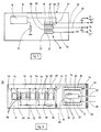
- the neutron device 10 consists of a hermetically sealed metal casing 12, inside which are mounted independently two elementary detectors 14, 16, arranged to obtain a large measurement dynamic for the nuclear reactor control.
- the first detector 14 is formed by an ionization chamber of the fission type, with uranium deposition, having a high sensitivity, and operating only in pulses.
- the second detector 16 is constituted by a compensated ionization chamber, having two polarization electrodes 18,22 and a measurement electrode 20.
- a first deposit 17 of boron is arranged on the electrodes 18,20 of the positive part of the chamber , and a second deposit 21 of uranium covers at least one of the electrodes 20, 22 of the negative part.
- the two detectors 14, 16 are supplied with the same positive voltage source (+ HT).
- the two positive electrodes of the detectors 14,16 are connected to a connection point 24 common to a first cable 26 of positive polarization.
- the output signal S1 of the device 10 comes from the pulses transmitted by the first detector 14 through the first cable 26.
- the electrode 22 of the second detector 16 is connected by a third cable 30 to a negative voltage source (-HT).
- -HT negative voltage source
- the three output signals S1, S2, S3 of the neutron detection device 10 are injected into an electronic circuit 32 (FIG. 3), which includes a pulse part to measure the counting rate, and a current part to measure the current delivered when the counting rate becomes too high.
- the signal S3 is applied to a current amplifier 31, while the pulses of each signal S2 and S1 are counted by a counter 34.36 after passing through a pulse amplifier 38.40, a discriminator 42.44 and a circuit 46.48.
- the ionization chamber of the fission type of the first detector 14 comprises a succession of pairs of positive electrodes 50, 52; 54.56; 58.60, nested between pairs of negative electrodes 62.64; 66.68, and connected respectively to support rods 70.72 with positive potential and negative.
- the support rods 70 with positive potential are fixed on an intermediate insulating base 73 and are electrically connected by a conductor 74 to the connection point 24, so as to be in connection with the source of positive voltage (+ HT).
- the support rods 72 with negative potential are also carried by the base 73 and connected to the metallic casing 12 by means of a resistor 76.
- the metallic casing 12 serves as a voltage reference by constituting the mass.
- Resistor 76 is intended to limit the current supplied to the positive supply common to the two detectors 14, 16 when the device 10 is subjected to high fluence flow levels.
- Each positive or negative electrode of the first detector 14 is in the form of a metal disc coated on one side with a deposit of uranium 235 whose thickness does not exceed the path of the fission products in uranium.
- the uranium deposit is represented by crosses in FIG. 2. This arrangement is intended to have the maximum of uranium per unit of surface and thus to have a good pulse sensitivity.
- a moderator 78 made of a hydrogenated material intended to slow down the neutrons.
- the pairs of positive and negative electrodes are arranged in parallel and alternately on their support rods 70, 72 so as to define a gas space between each of them.
- the surfaces of the electrodes in contact with the space gas are coated with uranium and thus define ionization chambers of the fission type.
- the useful signals delivered by the first detector 14 are pulses which are recovered on the cable 26 of positive polarization.
- the second detector 16 is an ionization chamber with boron deposition compensated for gamma radiation.
- the chamber comprises three coaxial and concentric electrodes 18, 20, 22 fixed on an insulating base 80 with guard rings.
- the external electrode 18 is positively biased by the source (+ HT) through the first cable 26, the central electrode 20 is used to collect the signals, and the internal electrode 22 is negatively biased by the third cable 30 to compensate for the contribution of the gammas.
- the electrodes of the first elementary chamber 90 defined between the external electrode 18 and the central electrode 20 are covered by the first deposit of boron 17.
- the electrodes of the second elementary chamber 92 defined between the central electrode 20 and the internal electrode 22 have no deposit of boron but the internal electrode 22 is coated with the second deposit 21 of uranium to form a small chamber to fission.
- the signals delivered by the measurement electrode 20 comprise pulses and a current.
- the neutron detection device 10 is designed to cover all the measurement dynamics thanks to the presence of the first and second detectors 14, 16, and of the three connection cables 26, 28, 30.
- the variation in fluence rate (on the ordinate) is between 0.1 to 1011 neutrons per square centimeter per second (nv), while the variation in gamma dose rate (in abscissa) extends between 0.01 to 105 Gray / hour (Gy / h).
Landscapes
- Physics & Mathematics (AREA)
- High Energy & Nuclear Physics (AREA)
- Health & Medical Sciences (AREA)
- Life Sciences & Earth Sciences (AREA)
- General Physics & Mathematics (AREA)
- Molecular Biology (AREA)
- Spectroscopy & Molecular Physics (AREA)
- Engineering & Computer Science (AREA)
- Plasma & Fusion (AREA)
- General Engineering & Computer Science (AREA)
- Measurement Of Radiation (AREA)
Applications Claiming Priority (2)
| Application Number | Priority Date | Filing Date | Title |
|---|---|---|---|
| FR90154462 | 1990-12-07 | ||
| FR9015462A FR2670301B1 (fr) | 1990-12-07 | 1990-12-07 | Dispositif de detection neutronique a dynamique etendue pour le controle et la commande des reacteurs nucleaires. |
Publications (2)
| Publication Number | Publication Date |
|---|---|
| EP0490783A2 true EP0490783A2 (de) | 1992-06-17 |
| EP0490783A3 EP0490783A3 (en) | 1992-09-02 |
Family
ID=9403092
Family Applications (1)
| Application Number | Title | Priority Date | Filing Date |
|---|---|---|---|
| EP19910420412 Withdrawn EP0490783A3 (en) | 1990-12-07 | 1991-11-21 | Neutron detection apparatus with extended dynamic range for checking and control of nuclear reactors |
Country Status (5)
| Country | Link |
|---|---|
| US (1) | US5192490A (de) |
| EP (1) | EP0490783A3 (de) |
| KR (1) | KR920013481A (de) |
| CA (1) | CA2057235A1 (de) |
| FR (1) | FR2670301B1 (de) |
Families Citing this family (16)
| Publication number | Priority date | Publication date | Assignee | Title |
|---|---|---|---|---|
| FR2697640B1 (fr) * | 1992-11-04 | 1994-12-02 | Merlin Gerin | Dispositif de détection neutronique pour mesurer la puissance d'un réacteur nucléaire. |
| RU2137155C1 (ru) * | 1998-10-12 | 1999-09-10 | Научно-исследовательский институт технологии материалов | Блок детекторов для измерения потока нейтронов |
| EP0994367B1 (de) * | 1998-10-14 | 2005-08-17 | General Electric Company | Neutronendetektor mit Doppelbereich und gammastrahlenbeständiger Schicht |
| DE10132550B4 (de) * | 2001-07-09 | 2008-07-10 | Bundesrepublik Deutschland, vertr. d. d. Bundesministerium für Wirtschaft und Technologie, dieses vertr. d. d. Präsidenten der Physikalisch-Technischen Bundesanstalt | Verfahren zur Bestimmung der Personendosis in gemischten Neutronen-/Photonen-Feldern sowie anderer Messgrößen in anderen Strahlenfeldern |
| US20050105675A1 (en) * | 2002-07-31 | 2005-05-19 | Shivakumar Sitaraman | Systems and methods for estimating helium production in shrouds of nuclear reactors |
| RU2227342C1 (ru) * | 2003-04-23 | 2004-04-20 | Бархатов Вячеслав Васильевич | Устройство для регистрации ядерных излучений |
| US7264725B2 (en) * | 2004-03-04 | 2007-09-04 | Celgard Inc. | Hollow fiber membrane contactor and method of making same |
| WO2006110159A2 (en) * | 2004-07-29 | 2006-10-19 | Kansas State University Research Foundation | Micro neutron detectors |
| US8712000B2 (en) * | 2007-12-13 | 2014-04-29 | Global Nuclear Fuel—Americas, LLC | Tranverse in-core probe monitoring and calibration device for nuclear power plants, and method thereof |
| FR2925700B1 (fr) * | 2007-12-24 | 2010-01-29 | Commissariat Energie Atomique | Dispositif de mesure de taux de comptage et dispositif d'etalonnage de chambre a fission associe |
| RU2549177C1 (ru) * | 2013-09-20 | 2015-04-20 | Открытое акционерное общество "Красная Звезда" | Устройство для регистрации ядерных излучений для систем управления и защиты ядерных реакторов "подвеска ионизационной камеры" |
| KR101462504B1 (ko) * | 2013-12-31 | 2014-11-19 | 국립대학법인 울산과학기술대학교 산학협력단 | 보론미터 |
| WO2016061553A1 (en) * | 2014-10-17 | 2016-04-21 | Silverside Detectors Inc. | Fissile neutron detector |
| RU2589350C1 (ru) * | 2015-04-21 | 2016-07-10 | Акционерное общество "Концерн радиостроения "Вега" | Устройство защиты радиоэлектронной аппаратуры при воздействии на неё импульсного ионизирующего излучения |
| US10317541B2 (en) | 2017-04-14 | 2019-06-11 | Silverside Detectors, Inc. | Advanced fissile neutron detection system and method |
| US10302781B2 (en) | 2017-04-15 | 2019-05-28 | Silverside Detectors, Inc. | Advanced thermal neutron detectors and associated methods |
Family Cites Families (11)
| Publication number | Priority date | Publication date | Assignee | Title |
|---|---|---|---|---|
| DE1090781B (de) * | 1957-03-16 | 1960-10-13 | Dr Boris Rajewsky | Anordnung zur getrennten Messung von Neutronen in einer gemischten Strahlung mittels zweier Ionisationskammern |
| US3311770A (en) * | 1963-05-13 | 1967-03-28 | Gen Electric | Gamma compensated neutron ion chamber |
| GB1046235A (en) * | 1963-08-23 | 1966-10-19 | English Electric Co Ltd | Radiation detectors |
| US3760183A (en) * | 1972-06-08 | 1973-09-18 | Gen Electric | Neutron detector system |
| FR2268353B1 (de) * | 1974-04-19 | 1977-10-14 | Commissariat Energie Atomique | |
| US4086490A (en) * | 1976-07-07 | 1978-04-25 | Westinghouse Electric Corporation | Wide range neutron detection system |
| US4582673A (en) * | 1983-09-12 | 1986-04-15 | General Electric Company | Fission-chamber-compensated self-powered detector for in-core flux measurement and reactor control |
| JPS60154447A (ja) * | 1984-01-23 | 1985-08-14 | Japan Atom Energy Res Inst | ガンマ線補償型中性子電離箱 |
| US5002720A (en) * | 1989-06-30 | 1991-03-26 | The United States Of America As Represented By The Secretary Of The Air Force | Electret enabled thermal neutron flux detection and measurement |
| FR2662816B1 (fr) * | 1990-06-05 | 1993-10-22 | Commissariat A Energie Atomique | Chambre a fission a grande gamme de mesure et dispositif de mesure de debit de fluence neutronique utilisant cette chambre a fission. |
| US5078951A (en) * | 1990-08-01 | 1992-01-07 | The United States Of America As Represented By The Secretary Of The Navy | High efficiency fast neutron threshold deflector |
-
1990
- 1990-12-07 FR FR9015462A patent/FR2670301B1/fr not_active Expired - Fee Related
-
1991
- 1991-11-21 EP EP19910420412 patent/EP0490783A3/fr not_active Withdrawn
- 1991-11-27 US US07/799,066 patent/US5192490A/en not_active Expired - Fee Related
- 1991-12-06 CA CA002057235A patent/CA2057235A1/en not_active Abandoned
- 1991-12-07 KR KR1019910022395A patent/KR920013481A/ko not_active Withdrawn
Also Published As
| Publication number | Publication date |
|---|---|
| EP0490783A3 (en) | 1992-09-02 |
| FR2670301B1 (fr) | 1993-02-12 |
| CA2057235A1 (en) | 1992-06-08 |
| FR2670301A1 (fr) | 1992-06-12 |
| KR920013481A (ko) | 1992-07-29 |
| US5192490A (en) | 1993-03-09 |
Similar Documents
| Publication | Publication Date | Title |
|---|---|---|
| EP0490783A2 (de) | Neutrondetektoranordnung mit erweitertem dynamischem Messbereich für Kontrolle und Steuerung von Kernreaktoren | |
| EP0227497B1 (de) | Verfahren zum Prüfen von Explosivstoffen | |
| FR2767201A1 (fr) | Dosimetre personnel de rayonnement | |
| JPS629870B2 (de) | ||
| EP0810631A1 (de) | Röntgenbilderzeugungsvorrichtung hoher Auflösung | |
| US4445036A (en) | Solid state fast-neutron spectrometer/dosimeter and detector therefor | |
| FR2508656A1 (fr) | Compteur proportionnel de neutrons de grande superficie et detecteur controleur de sortie | |
| EP0461015B1 (de) | Vorrichtung zur Messung des Neutronenflusses | |
| EP0615274A1 (de) | Bilderzeugungsvorrichtung von ionisierenden Partikeln mittels einer Mehrdraht-Proportionalkammer | |
| US3366790A (en) | Nuclear radiation detector comprising multiple ionization chamber with hemisphericalshaped electrodes | |
| FR2516665A1 (fr) | Detecteur de concentration de gaz radioactifs a large plage | |
| US5734689A (en) | Thermal neutron detector | |
| EP0051520A1 (de) | Tragbares Gerät zur Strahlungsmessung unter Anwendung eines Halbleiterdetektors mit elektronischer Energiekompensation | |
| EP0391789A2 (de) | Individuelle Schaltung zur Messung des Neutronendosisäquivalents | |
| JP3151487B2 (ja) | 放射線検出方法 | |
| EP0009450A1 (de) | Gamma-Strahlungsdetektor für die Prüfung von Brennstoffstäben | |
| FR2767926A1 (fr) | Procede et appareil de mesure non destructrice de materiaux fissiles dans des dechets solides radioactifs | |
| Curtiss | The Geiger-Müller Counter | |
| EP0742451B1 (de) | System zur Überwachung des Signals einer breitbandigen Messvorrichtung für Nuklearstrahlung | |
| US4039808A (en) | Solid state ionization chamber of silicon pn-junction type | |
| FR2501369A1 (fr) | Detecteur photo-electrique | |
| JPS6132335Y2 (de) | ||
| Hutton et al. | Diamond-based radiation detectors for very high dose rate environments-16207 | |
| Joshi | Charge spreading and RC measurement in T2K-TPC Resistive Anode Micromegas | |
| WO2000003266A1 (en) | Radiation detector |
Legal Events
| Date | Code | Title | Description |
|---|---|---|---|
| PUAI | Public reference made under article 153(3) epc to a published international application that has entered the european phase |
Free format text: ORIGINAL CODE: 0009012 |
|
| AK | Designated contracting states |
Kind code of ref document: A2 Designated state(s): BE CH DE ES GB IT LI NL SE |
|
| PUAL | Search report despatched |
Free format text: ORIGINAL CODE: 0009013 |
|
| AK | Designated contracting states |
Kind code of ref document: A3 Designated state(s): BE CH DE ES GB IT LI NL SE |
|
| 17P | Request for examination filed |
Effective date: 19921128 |
|
| STAA | Information on the status of an ep patent application or granted ep patent |
Free format text: STATUS: THE APPLICATION IS DEEMED TO BE WITHDRAWN |
|
| 18D | Application deemed to be withdrawn |
Effective date: 19940601 |