EP0490906B1 - Wasserstrahl-schneideinrichtung für einen sich bewegenden papierbogen - Google Patents
Wasserstrahl-schneideinrichtung für einen sich bewegenden papierbogen Download PDFInfo
- Publication number
- EP0490906B1 EP0490906B1 EP90912069A EP90912069A EP0490906B1 EP 0490906 B1 EP0490906 B1 EP 0490906B1 EP 90912069 A EP90912069 A EP 90912069A EP 90912069 A EP90912069 A EP 90912069A EP 0490906 B1 EP0490906 B1 EP 0490906B1
- Authority
- EP
- European Patent Office
- Prior art keywords
- hose
- jet
- reel
- chain
- conduit
- Prior art date
- Legal status (The legal status is an assumption and is not a legal conclusion. Google has not performed a legal analysis and makes no representation as to the accuracy of the status listed.)
- Expired - Lifetime
Links
Images








Classifications
-
- B—PERFORMING OPERATIONS; TRANSPORTING
- B65—CONVEYING; PACKING; STORING; HANDLING THIN OR FILAMENTARY MATERIAL
- B65H—HANDLING THIN OR FILAMENTARY MATERIAL, e.g. SHEETS, WEBS, CABLES
- B65H19/00—Changing the web roll
- B65H19/22—Changing the web roll in winding mechanisms or in connection with winding operations
- B65H19/26—Cutting-off the web running to the wound web roll
- B65H19/265—Cutting-off the web running to the wound web roll using a cutting member moving linearly in a plane parallel to the surface of the web and along a direction crossing the web
-
- B—PERFORMING OPERATIONS; TRANSPORTING
- B26—HAND CUTTING TOOLS; CUTTING; SEVERING
- B26F—PERFORATING; PUNCHING; CUTTING-OUT; STAMPING-OUT; SEVERING BY MEANS OTHER THAN CUTTING
- B26F3/00—Severing by means other than cutting; Apparatus therefor
-
- B—PERFORMING OPERATIONS; TRANSPORTING
- B26—HAND CUTTING TOOLS; CUTTING; SEVERING
- B26F—PERFORATING; PUNCHING; CUTTING-OUT; STAMPING-OUT; SEVERING BY MEANS OTHER THAN CUTTING
- B26F3/00—Severing by means other than cutting; Apparatus therefor
- B26F3/004—Severing by means other than cutting; Apparatus therefor by means of a fluid jet
-
- D—TEXTILES; PAPER
- D21—PAPER-MAKING; PRODUCTION OF CELLULOSE
- D21F—PAPER-MAKING MACHINES; METHODS OF PRODUCING PAPER THEREON
- D21F1/00—Wet end of machines for making continuous webs of paper
- D21F1/34—Construction or arrangement of spraying pipes
-
- D—TEXTILES; PAPER
- D21—PAPER-MAKING; PRODUCTION OF CELLULOSE
- D21F—PAPER-MAKING MACHINES; METHODS OF PRODUCING PAPER THEREON
- D21F7/00—Other details of machines for making continuous webs of paper
- D21F7/006—Cutting the edges of the paper-web
-
- D—TEXTILES; PAPER
- D21—PAPER-MAKING; PRODUCTION OF CELLULOSE
- D21F—PAPER-MAKING MACHINES; METHODS OF PRODUCING PAPER THEREON
- D21F7/00—Other details of machines for making continuous webs of paper
- D21F7/04—Paper-break control devices
-
- D—TEXTILES; PAPER
- D21—PAPER-MAKING; PRODUCTION OF CELLULOSE
- D21G—CALENDERS; ACCESSORIES FOR PAPER-MAKING MACHINES
- D21G9/00—Other accessories for paper-making machines
- D21G9/0063—Devices for threading a web tail through a paper-making machine
-
- B—PERFORMING OPERATIONS; TRANSPORTING
- B65—CONVEYING; PACKING; STORING; HANDLING THIN OR FILAMENTARY MATERIAL
- B65H—HANDLING THIN OR FILAMENTARY MATERIAL, e.g. SHEETS, WEBS, CABLES
- B65H2301/00—Handling processes for sheets or webs
- B65H2301/40—Type of handling process
- B65H2301/41—Winding, unwinding
- B65H2301/417—Handling or changing web rolls
- B65H2301/4187—Relative movement of core or web roll in respect of mandrel
- B65H2301/4189—Cutting
- B65H2301/41898—Cutting threading tail and leading it to new core
-
- B—PERFORMING OPERATIONS; TRANSPORTING
- B65—CONVEYING; PACKING; STORING; HANDLING THIN OR FILAMENTARY MATERIAL
- B65H—HANDLING THIN OR FILAMENTARY MATERIAL, e.g. SHEETS, WEBS, CABLES
- B65H2301/00—Handling processes for sheets or webs
- B65H2301/50—Auxiliary process performed during handling process
- B65H2301/51—Modifying a characteristic of handled material
- B65H2301/515—Cutting handled material
- B65H2301/5153—Details of cutting means
- B65H2301/51534—Water jet
Definitions
- This application pertains to apparatus which controllably advances a high pressure water jet across a rapidly moving sheet of paper to cut a narrow tail along one side of the paper sheet and then gradually widens the cut, after the tail has been threaded through part of a paper making machine, to allow the full width of the paper sheet to be drawn through that part of the machine according to the preamble of the claims, as known from US-A-3625813.
- a rapidly moving, continuous sheet of paper must be threaded through different parts of the machine as the paper is made.
- one such stage occurs when the moving, continuous sheet of paper passes at high speed over a plurality of dryer rolls and then through a stack of calender rolls which calender the paper by imparting a finish of desired smoothness thereto. Since it is difficult to guide the full width of the moving paper sheet off the last dryer roll and then feed it through the calender stack, a narrow "tail" is cut to one side of the moving sheet as it comes off the last dryer roll, the balance of the moving sheet being allowed to fall into a broke pit for reprocessing. The tail is more easily fed through the calender stack and, once threaded, can be used to draw the full width of the paper sheet through the calender stack.
- tails have been cut in lightweight paper by directing a blast of compressed air at the moving paper sheet. This however produces a torn, ragged edge which can be difficult to pass through the infeed nips of the calender roll stack. Paper tails have been produced in medium or heavier weight paper sheets by hand-tearing, which is a dangerous procedure that has resulted in serious operator injuries, and which also tends to produce a torn, ragged or folded edge.
- Dulled knives can also fail to cut reliably on sheet break detection.
- Paper making machines employ sheet break sensors to detect and signal breakage of the moving paper sheet at points upstream from the dryer roll/calender stack interface. If the sheet breaks, then it must be cleanly severed ahead of the break and diverted into the broke pit to prevent the broken portion of the sheet from fouling the calender stack. Once the broken portion of the sheet has passed into the broke pit, and proper flow of the full width sheet over the dryer rolls has been reestablished, a new tail is cut, threaded through the calender stack, and then used to draw the unbroken sheet through the calender stack.
- the tail cutting knife On sheet break detection, the tail cutting knife is rapidly drawn across the full width of the sheet with the object of cleanly severing the sheet as aforesaid. However, if the knife is dull, then it may fail to cut the sheet completely, cleanly, or at all. If the sheet is not cleanly severed, then portions of the sheet may overlap as the sheet enters the calender stack, causing "roll bounce", which may over time cause “barring”, a form of marking of the calender rolls, which may eventually necessitate expensive, time-consuming resurfacing of the rolls and consequential downtime of the paper making equipment.
- the present invention employs a high pressure water jet to cut a tail in a rapidly moving paper sheet.
- the water jet is not dulled by the cutting operation, as is a mechanical knife.
- Water jets have previously been used in paper cutting applications.
- United States Patent No. 3,625,813 issued 7 December, 1971 for an invention of Eckelman discloses a water jet capable of cutting paper at the "wet end" of a paper making machine.
- the present invention employs a high pressure water jet capable of cutting paper at the "dry end” of a paper making machine.
- a high pressure hose delivers highly pressurized water to the cutter, which is slidably advanced or retracted relative to the paper. Care is taken to avoid subjecting the hose to tension or compression forces, and to prevent repeated flexing of the hose ends, as the hose is paid out from or taken up during slidable advance or retraction of the cutter.
- the invention provides apparatus for controllably advancing a high pressure water jet across a moving paper sheet to cut a tail therefrom.
- the apparatus comprises a hose for supplying pressurized water to the jet, drive means for advancing the jet and the hose at the same rate across the paper sheet, and hose support means for supporting the hose during the advancing operation, without applying tension or compression forces to the hose.
- the hose support means preferably comprises a rotatable reel for coilingly receiving the hose.
- the drive means preferably comprises a chain coupled between the jet and the reel, whereby movement of the jet causes corresponding movement of the chain, which causes corresponding movement of the reel.
- the chain is coupled to the reel by a first sprocket coaxially aligned with the reel. The first sprocket has the same pitch diameter as the hose, when the hose lies coiled around the reel.
- the drive means further comprises a linear cylinder having a slidably displaceable piston.
- the jet and the chain are coupled to the piston for slidable displacement therewith.
- An idler sprocket is advantageously provided.
- the first sprocket and the reel are disposed at one end of the cylinder, the idler sprocket is disposed at the opposite end of the cylinder, and the chain traverses an endless loop from the piston, around the first sprocket, and around the idler sprocket, returning to the piston.
- the idler sprocket is preferably mounted for adjustable positioning thereof, thereby facilitating adjustment of the tension on the chain.
- Hose guiding means are provided for guiding the hose onto the reel in horizontally spaced coils and for preventing vertical stacking of the coils.
- the hose guiding means may comprise a tapered roller disposed between the reel and the jet, adjacent the reel, with the lower surface of the tapered roller aligned slightly below the upper surface of the reel.
- the reel is supported on a rotatable axle.
- Pressurized water coupling means are provided for supplying pressurized water through the axle to the hose.
- the pressurized water coupling means comprises a first high pressure conduit having first and second ends; a channel in the axle for receiving the first conduit such that the first conduit first end protrudes longitudinally from one end of the axle and the first conduit second end protrudes transversely from the central region of the axle; rotatable coupling means for rotatably coupling the first conduit first end to a source of pressurized water; and, hose coupling means for coupling the first conduit second end to the hose.
- the hose coupling means further comprises a second high pressure conduit extending from the first conduit second end toward the circumference of the reel, thereby increasing the radius through which the hose bends for coupling to the first conduit second end. This prevents repeated flexing of the hose end at its point of connection to the source of pressurized water.
- a chain position sensing means is provided for sensing the position of a reference point on the chain and for producing an output signal representative of that position.
- the chain position sensing means may comprise a third sprocket drivingly engageable by the chain, and a shaft encoder coupled to the third sprocket for producing an output signal proportional to the number of revolutions of the third sprocket.
- Reset means may be provided for resetting the output signal to a preselected value whenever the reference point coincides with a normally inactive storage position of the jet.
- the reset means may comprise a proximity switch for detecting movement of the jet into the storage position and for producing an output signal representative thereof. The reset means may also interrupt the supply of pressurized water to the jet whenever the jet is in its storage position.
- Power fail detector means may be provided for interrupting the supply of pressurized water to the jet and for moving the jet into the normally inactive storage position upon reconnection of electrical power to the apparatus following disconnection of power therefrom.
- a splitter jet may be provided to controllably, intermittently direct a high pressure water jet toward the central region of the paper sheet which falls into the broke pit.
- Figure 1 is a partially fragmented, partially exploded perspective illustration of a high pressure water jet paper tail cutter constructed in accordance with the preferred embodiment of the invention.
- Figure 2 is a perspective illustration of the rear side of the hose reel portion of the apparatus depicted in Figure 1.
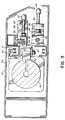
- Figure 3 is a cross-sectional illustration taken with respect to the line 3-3 of Figure 1.
- Figure 4 is a partially fragmented, exploded pictorial illustration of the fixed, high pressure water "splitter” jet of the preferred embodiment.
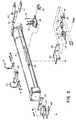
- Figure 5 is an exploded pictorial illustration of the rodless linear air cylinder and movable tail cutter jet of the preferred embodiment.
- Figure 6 is a rear elevation view of the hose reel portion of the apparatus depicted in Figure 1; most of the high pressure water supply circuitry having been omitted from Figure 6.
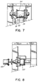
- Figure 7 is a cross-sectional illustration taken with respect to the line 7-7 of Figure 6.
- Figure 8 is a cross-sectional illustration taken with respect to the line 8-8 of Figure 6.
- Figure 9 is a right end elevation view of the hose reel depicted in Figure 6.
- Figure 10 is a rear elevation view of the portion of the high pressure water supply manifold circuitry of the preferred embodiment.
- Figure 11 is a cross-sectional illustration taken with respect to the line 11-11 of Figure 10.
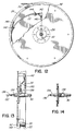
- Figure 12 is a partially fragmented rear elevation view of a portion of the hose reel of the preferred embodiment, showing the coupling of the high pressure water supply to the hose.
- Figure 13 is a right end elevation view of the hose reel depicted in Figure 12.
- Figure 14 is a top plan view of the hose reel axle of the preferred embodiment.
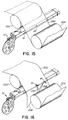
- Figure 15 is a simplified pictorial illustration depicting a full width moving paper sheet passing off the last of a sequence of dryer rolls, over a high pressure water jet paper tail cutter constructed in accordance with the preferred embodiment of the invention, and onto the first of a stack of calender rolls.
- Figure 15 depicts the high pressure water jet paper tail cutter in its inactive state.
- Figure 16 depicts the tail cutter jet being drawn across the paper sheet to sever the sheet, which then falls into a broke pit. Figure 16 also shows the splitter jet splitting the severed sheet as it falls into the broke pit.
- Figure 17 depicts the full width sheet falling into the broke pit, while being split by the splitter jet.
- Figure 18 depicts the tail cutter jet cutting a tail along one side of the moving paper sheet for threading through the calender stack.
- Figure 19 depicts the tail cutter jet being drawn across the moving paper sheet, toward the splitter jet, to widen the segment of the paper sheet which is drawn through the calender stack by the threaded tail.
- Figure 20 depicts tail cutter jet being drawn across the moving paper sheet, past the now inoperative splitter jet, to further widen the segment of the paper sheet which is drawn through the calender stack.
- Figure 21 depicts the high pressure water jet paper tail cutter returned to its inactive state, with the full width moving paper sheet being drawn into the calender stack and the end of the severed sheet falling into the broke pit.
- FIG. 1 depicts a high pressure water jet paper tail cutter apparatus generally designated 10.
- Apparatus 10 incorporates an elongate air-pressurized housing 12, which encloses cylinder 14, extended upper and lower portions of drive chain 16, movable tail cutter jet 18, fixed splitter jet 20, a portion of hose 22 and idler sprocket 24.
- Tail cutter jet 18 and hose 22 are controllably slidably displaceable along cylinder 14, as hereinafter explained.
- hose 22 is supported by reel 26 in a manner which avoids the application of tension or compression forces to hose 22 and which prevents repeated flexing of the hose end at its point of connection to the high pressure water supply.
- Shrouds 28, 30 normally cover reel 26, preventing foreign substances from fouling chain 16, hose 22 or reel 26.
- shroud 32 normally encloses idler 24 at the opposite end of housing 12.
- Apparatus 10 is supported at an appropriate height on stanchions 33 (only one of which is shown).
- Cylinder 14 is preferably an ORIGA TM rodless linear pneumatic cylinder available from Origa Corporation of Elmhurst, Illinois. Cylinder 14 is sized to extend longitudinally through housing 12 such that the range of slidable displacement of slider block 34 coupled to the slidably displaceable piston (not shown) of cylinder 14 exceeds the full width of the paper sheet with which apparatus 10 is to be utilized. As best seen in Figures 3 and 5, movable tail cutter jet 18 is directly coupled to slider block 34 via carriage 36. The high pressure water delivery end of hose 22 is also coupled to slider block 34 via carriage 36. More particularly, a pair of split blocks 38, 40 clamp the end of hose 22.
- ORIGA TM rodless linear pneumatic cylinder available from Origa Corporation of Elmhurst, Illinois. Cylinder 14 is sized to extend longitudinally through housing 12 such that the range of slidable displacement of slider block 34 coupled to the slidably displaceable piston (not shown) of cylinder 14 exceeds the full width of the paper sheet with which apparatus 10 is to be
- Blocks 38, 40 are bolted to the front face of carriage 36, which is in turned bolted to the underside of slider block 34.
- An elbow connector 42 conveys pressurized water from hose 22 into conduit 44, which is clamped between split blocks 46 by bolts passed through blocks 46 into arm 48 which projects forwardly from the front face of carriage 36.
- Conduit 44 conveys pressurized water to tail cutter jet 18, which emits water pressurized to about 1,400 kg/cm2 (about 20,000 p.s.i.) through a .0127 cm (.005'') diameter orifice.
- Chain connector plate 54 is in turn bolted to chain connector plate 54.
- the opposed ends of chain 16 are coupled together by chain connector 56 to form an endless loop chain, as hereinafter explained.
- Cylinder 14 is supported within housing 12 on pad 58 and held in place by clamps 60, 62; end brackets 64, 66 and pads 68, 70, 72, 74.
- splitter jet 20 is fixed within housing 12 at about the midpoint thereof.
- Rigid high pressure conduit 76 conveys pressurized water from elbow connector 78 to elbow connector 80, which in turn supplies jet 20 through conduit 82.
- Clamps 84 attach conduit 76 at intervals to mounting rail 86, which is suspended from the internal, upper surface of housing 12, as shown in Figure 3.
- Conduit 82 is held in position by stop bracket 88, which is also connected to the internal, upper surface of housing 12, as shown in Figure 3.
- Hose 22 is preferably a SPIR-STAR TM super high pressure hose available from D&G Industries, Inc. of Holbrook, New York. As best seen in Figures 1, 2, 6, 9 and 12, the portion of hose 22 which does not extend within housing 12 is coiled upon reel 26 which rotates about axle 90 ( Figures 9, 13 and 14). Care must be taken to avoid subjecting hose 22 to tension or compression forces, and to prevent repeated flexing of the hose ends, as hose 22 is paid out from or taken up on reel 26 during slidable advance or retraction of tail cutter jet 18 along cylinder 14. The application of tension or compression forces to hose 22 is avoided, in the preferred embodiment, by entraining chain 16 around a first sprocket 92 coaxial with axle 90.
- the pitch diameter of sprocket 92 equals pitch diameter of hose 22 when hose 22 is coiled upon reel 26.
- the "drive means" comprising cylinder 14, drive chain 16 and sprocket 92 thus advances or retracts hose 22 at the same rate as tail cutter jet 18.
- hose 22 is guided onto reel 26 in horizontally spaced coils in a manner which prevents vertical stacking of the coils. If the hose coils became vertically stacked one above the other, then hose 22 would no longer have the same pitch diameter as sprocket 92. This would in turn allow hose 22 to be paid out from or taken up on reel 26 at a speed which differed from the speed at which tail cutter jet 18 was advanced or retracted along cylinder 14, subjecting hose 22 to potentially damaging tension or compression forces. Accordingly, "hose guiding means"; namely, tapered roller 94 are provided for guiding hose 22 onto reel 26 in controlled fashion.
- tapered roller 94 is disposed between reel 26 and jet 18, adjacent reel 26, with lower surface 96 of roller 94 aligned slightly below the upper surface of reel 26.
- roller 94 guides hose 22 onto reel 26 in a single layer of horizontally spaced coils as shown in Figure 7, while preventing vertical stacking of the coils.
- Sprocket 98 ( Figures 1, 6 and 9) elevates chain 16 so that it clears roller 94.
- Shaft encoder 100 ( Figures 2, 6 and 8) serves as a "chain position sensing means" for sensing the position of a reference point on chain 16 (i.e. the position of the mid point of chain connector 56, which is in turn representative of the position of the high pressure water jet orifice of tail cutter jet 18) and for producing an output signal representative of that position.
- Sprocket 102 is drivingly engaged by the lower section of chain 16 as it emerges from elongate housing 12 to engage sprocket 92.
- Shaft encoder 100 is drivingly coupled to sprocket 102 and produces an output signal proportional to the number of revolutions of sprocket 102.
- a "reset means” such as magnetic proximity switch (not shown) may be provided for resetting the output signal produced by encoder 100 to a preselected value (i.e. zero) whenever the proximity switch detects movement of the reference point aforesaid to coincide with a normally inactive storage position of tail cutter jet 18. This eliminates slight errors in the position signal output by encoder 100 which could otherwise accumulate over time to produce an erroneous indication of the position of jet 18. Actuation of the reset means by movement of jet 18 to its storage position also preferably interrupts the supply of pressurized water to jet 18.
- An electronic power fail detector means may also be provided to interrupt the supply of pressurized water to jet 18 and to actuate apparatus 10 to move jet 18 into its normally inactive storage position whenever electrical power is reconnected to apparatus 10 following disconnection of electrical power therefrom. This ensures that jet 18 is not activated in circumstances in which the position of jet 18, or the operational state of other components incorporated in apparatus 10, may be unknown.
- Chain 16 traverses an endless loop. More particularly, one end of chain 16 is coupled to chain connector 56 as aforesaid. Chain 16 passes from connector 56 around idler sprocket 24 and then returns underneath connector 56 to pass over sprocket 102, and thence over sprockets 92 and 98, from which it returns to couple, at its opposite end, to connector 56.
- Idler sprocket 24 is mounted at the end of housing 12 in such a manner it may be adjustably slidably displaced in order to regulate the tension on drive chain 16. This location of the chain tensioning mechanism facilitates concurrent adjustment of the upper and lower lengths of chain which pass through housing 12.
- Pressurized water is supplied to hose 22 by a waterjet intensifier (not shown) such as the STREAMLINE TM model 25S, 40S or 50S intensifiers available from Ingersoll-Rand of Baxter Springs, Kansas. These devices are capable of supplying water pressurized to between about 850 kg/cm2 and 3,800 kg/cm2 (about 12,000 - 55,000 p.s.i.). A water pressure of about 1,400 kg/cm2 (about 20,000 p.s.i.) has been found suitable for operation of apparatus 10. Pressurized water supplied by the waterjet intensifier enters via conduit 104 ( Figures 2 and 10) and passes through stem valve 106, conduit 108, elbow 110, conduit 112, and filter 114 to cross connector 116.
- a waterjet intensifier such as the STREAMLINE TM model 25S, 40S or 50S intensifiers available from Ingersoll-Rand of Baxter Springs, Kansas. These devices are capable of supplying water pressurized to between about 850 kg/c
- Cross connector 116 diverts a portion of the pressurized water flow through conduit 118 and control valve 120 into conduit 122 which is coupled to rigid high pressure conduit 76 and thence to splitter jet 20.
- Cross connector 116 diverts the other portion of the pressurized water flow through conduit 124, control valve 126, conduit 128, and swivel connector 130 to coupler 132 ( Figure 11) for delivery to hose 22.
- a "pressurized water coupling means” namely, first high pressure conduit 134 (Figure 13) delivers the pressurized water from coupler 132 through hose reel axle 90 to hose 22, as will now be described with reference to Figures 12, 13 and 14.
- First high pressure conduit 134 has a first end 136 and a second end 138.
- a channel is cut in axle 90 to receive conduit 134 such that conduit first end 136 protrudes longitudinally from one end of axle 90 and conduit second end 138 protrudes transversely from the central region of axle 90.
- Swivel connector 130 ( Figures 9, 10 and 11) serves as a "rotatable coupling means” for rotatably coupling conduit first end 136 to the source of pressurized water while accommodating rotational movement of reel 26, axle 90 and first high pressure conduit 134.
- a "hose coupling means" namely, second high pressure conduit 140 couples first conduit second end 138 to hose 22 through elbow 142.
- second high pressure conduit 140 extends from first conduit second end 138 toward the circumference of reel 26, thereby increasing the radius through which hose 22 bends for coupling to first conduit second end 138. This is important to avoid imposing undesirable stresses on the end of hose 22 by repeatedly flexing the hose end through a small radius.
- Hose 22 is clamped to one internal side of reel 26 by clamp 144 and passes through reel aperture 146 onto the circumferential hose winding surface 148 of reel 26.
- Figure 15 is a simplified pictorial illustration depicting a full width moving paper sheet 200 passing off the last roller 202 of a sequence of dryer rolls, over apparatus 10, and onto the first roll 204 of a stack of calender rolls.
- Figure 15 depicts apparatus 10 in its inactive state in which no pressurized water flows to tail cutter jet 18 or to splitter jet 20, and in which tail cutter jet 18 remains stationary in its normally inactive storage position off to one side of paper sheet 200.
- Figure 16 depicts tail cutter jet 18 being drawn across paper sheet 200, while emitting a high pressure water jet stream, thereby severing sheet 200 along an angular line 206 determined by the relative speeds of tail cutter jet 18 and paper sheet 200.
- the severed end 208 of sheet 200 falls into a broke pit, carrying the balance of sheet 200 with it.
- jet 18 may be actuated to emit a high pressure water jet stream even before jet 18 is drawn across sheet 200.
- Prior art mechanical cutters which cannot be advanced from a point off to one side of the moving paper sheet into the edge of the sheet without breaking the sheet.
- Prior art mechanical cutters must be plunged into a central portion of the moving paper sheet and then drawn to each edge of the sheet to sever it.
- jet 18 severs sheet 200 by traversing a single pass from one side of the sheet to the other.
- Figure 16 also depicts actuation of splitter jet 20 which splits severed sheet 208, as shown at 210, by directing a high pressure water jet stream at severed sheet 208 as it falls into the broke pit. This breaks up the severed sheet, making it somewhat easier to reprocess.
- tail cutter jet 18 has completely severed sheet 200 and is positioned at rest (i.e. the supply of pressurized water to jet 18 has been turned off) to the opposite side of the paper sheet.
- the full width of sheet 200 falls into the broke pit, while being split by the splitter jet 20 for reprocessing.
- Figure 18 depicts tail cutter jet 18 positioned inwardly about 10 - 15 cm (about 4" - 6") from the edge of paper sheet 200 and actuated to cut a tail 212 along one side of the moving paper sheet for threading through the calender stack. The balance of sheet 200 continues to fall into the broke pit, while being split by splitter jet 20.
- Figure 19 depicts the widening of tail 212, after successful threading of the initial narrow tail through the calender stack. This is accomplished by continuing the emission of a high pressure water jet stream from tail cutter jet 18, while drawing tail cutter jet 18 across moving paper sheet 200, toward splitter jet 20, to widen the segment of the paper sheet drawn through the calender stack by the previously threaded portion of tail 212. As depicted in Figure 19, splitter jet 20 is deactivated just before tail cutter jet 18 passes beneath splitter jet 20.
- Figure 20 depicts the continued drawing of tail cutter jet 18 across moving paper sheet 200, past now inoperative splitter jet 20, to further widen the segment 212 of paper sheet 200 which is drawn through the calender stack.
- Figure 21 depicts apparatus 10 returned to its inactive state, with the full width moving paper sheet 200 being drawn into the calender stack and the end of severed sheet 208 falling into the broke pit.
- Tail cutter jet 18 has returned to its normally inactive storage position and its source of pressurized water has been turned off.
- sprockets could be replaced with rollers or sheaves.
- Drive chain 16 could be replaced with a cable wound around a drum to yield the same pitch diameter as hose 22 coiled upon reel 26.
- sprockets 24, 92 could be replaced by controllable drive mechanisms, which would obviate the need for cylinder 14 while still facilitating travel of hose 22 at the same rate as tail cutter jet 18, without subjecting hose 22 to tension or compression forces, or to repeated flexing of the hose ends.
Landscapes
- Life Sciences & Earth Sciences (AREA)
- Forests & Forestry (AREA)
- Engineering & Computer Science (AREA)
- Mechanical Engineering (AREA)
- Perforating, Stamping-Out Or Severing By Means Other Than Cutting (AREA)
- Fats And Perfumes (AREA)
- Paper (AREA)
- Cosmetics (AREA)
- Detergent Compositions (AREA)
- Organic Low-Molecular-Weight Compounds And Preparation Thereof (AREA)
- Low-Molecular Organic Synthesis Reactions Using Catalysts (AREA)
- Sampling And Sample Adjustment (AREA)
- Measurement Of Force In General (AREA)
- Transformer Cooling (AREA)
Claims (19)
- Vorrichtung (10) zum gesteuerten Vorwärtsbewegen einer Hochdruckwasserdüse (18) über einen sich bewegenden Papierbogen (200) und eines Schlauches (22), welcher unter Druck stehendes Wasser an die Düse (18) liefert, um dadurch einen Streifen (212) von dem Papierbogen (200) zu schneiden, wobei die Vorrichtung (10) Antriebsmittel (14, 16, 92) zum Vorwärtsbewegen und Zurückziehen der Düse (18) und des Schlauches (22) mit derselben Geschwindigkeit über den Papierbogen (200) und Schlauch-Stützmittel mit einer drehbaren Rolle (26) zum aufgespulten Aufnehmen und Stützen des Schlauches (22) während der Vorschiebe- und Rückziehoperationen aufweist, dadurch gekennzeichnet, daß die Antriebsmittel eine zwischen der Düse (18) und der Rolle (26) gekoppelte Kette (16) oder ein Kabel aufweist, wodurch die Bewegung der Düse (18) eine entsprechende Bewegung der Kette (16) oder des Kabels bewirkt, was eine entsprechende Bewegung der Rolle (26) bewirkt, wodurch der Schlauch (22) so vorwärtsbewegt und zurückgezogen wird, daß die Kette (16) oder das Kabel und die Rolle (26) die Zug- oder Druckkräfte, die mit solchen Vorwärts- oder Rückwärtsbewegungen verbunden sind, aufnehmen und dadurch den Schlauch (22) von diesen Kräften entlasten.
- Vorrichtung nach Anspruch 1, wobei:(a) die Kette (16) mit der Rolle (26) durch ein erstes Zahnrad (92), das koaxial mit der Rolle (26) ausgerichtet ist, verbunden ist; und(b) das erste Zahnrad (92) denselben Rolldurchmesser wie der Schlauch (22) hat, wenn der Schlauch (22) vollständig zurückgezogen und um die Rolle (26) gewickelt ist.
- Vorrichtung nach Anspruch 1, bei der das Kabel mit der Rolle (26) verbunden ist, indem das Kabel über eine mit der Rolle (26) verbundenen Trommel gewickelt wird, damit das aufgewickelte Kabel einen effektiven Rolldurchmesser erhält, der gleich dem Rolldurchmesser des Schlauches (22) ist, wenn der Schlauch (22) vollständig zurückgezogen und um die Rolle (26) gewunden ist.
- Vorrichtung nach Anspruch 2 oder 3, wobei:(a) die Antriebsmittel weiterhin einen linearen Zylinder (14) mit einem gleitbar verschiebbaren Kolben aufweisen; und(b) die Düse (18) und die Kette (16) oder das Kabel mit dem Kolben für eine gleitfähige Verschiebung mit diesem verbunden sind.
- Vorrichtung nach Anspruch 4, die weiterhin ein Führungszahnrad (24) oder eine Rolle aufweist und wobei:(a) das erste Zahnrad (92) und die Rolle (26) an einem Ende des Zylinders (14) angeordnet sind;(b) das Führungszahnrad (24) oder die Rolle am gegenüberliegenden Ende des Zylinders (14) angeordnet ist; und(c) die Kette (16) oder das Kabel eine endlose sich von dem Kolben um das erste Zahnrad (92) herum, um ein Führungszahnrad (24) oder Rolle herum und zu dem Kolben erstreckende Schleife durchläuft.
- Vorrichtung nach Anspruch 5, wobei das Führungszahnrad (24) oder die Rolle so angeordnet ist, daß seine/ihre Position eingestellt werden kann, wodurch eine Einstellung der Ketten (16)- oder Kabelspannung erleichtert wird.
- Vorrichtung nach Anspruch 1, die weiterhin Schlauchführungsmittel (94) zum Führen des Schlauches (22) auf die Rolle (26) in horizontal beabstandeten Windungen und zum Verhindern eines vertikalen Stapelns der Windungen aufweist.
- Vorrichtung nach Anspruch 1, die weiterhin Schlauchführungsmittel zum Führen des Schlauches (22) auf die Rolle (26) in horizontal beabstandeten Windungen und zum Verhindern eines vertikalen Stapelns der Windungen aufweist, wobei die Schlauchführungsmittel eine sich verjüngende Rolle (94) aufweisen, die zwischen der Rolle (26) und der Düse (18) nahe der Rolle (26) vorgesehen ist, wobei die untere Oberfläche (96) der sich verjüngenden Rolle (94) leicht unterhalb der oberen Oberfläche der Rolle (26) ausgerichtet ist.
- Vorrichtung nach Anspruch 1, wobei die Rolle (26) auf einer drehbaren Achse (90) gestützt ist, und die Vorrichtung weiterhin Druckwasser-Kupplungsmittel (134) zum Liefern des unter Druck stehenden Wassers durch die Achse (90) an den Schlauch (22) aufweist.
- Vorrichtung nach Anspruch 1, wobei die Rolle (26) auf einer drehbaren Achse (90) gestützt ist und die Vorrichtung weiterhin aufweist:(a) eine erste Hochdruckleitung (134) mit einem ersten und einem zweiten Ende (136, 138);(b) einen Kanal in der Achse (90) zum Aufnehmen der ersten Leitung (134), so daß das erste Ende (136) der ersten Leitung in Längsrichtung von einem Ende der Achse (90) vorsteht und das zweite Ende (138) der ersten Leitung in Querrichtung von dem Mittelbereich der Achse (90) vorsteht;(c) drehbare Kupplungsmittel (130) zum drehbaren Verbinden des ersten Endes (136) der ersten Leitung mit einer Quelle von unter Druck stehendem Wasser; und(d) Schlauch-Kupplungsmittel (140) zum Verbinden des zweiten Endes (138) der ersten Leitung mit dem Schlauch (22).
- Vorrichtung nach Anspruch 10, bei der die Schlauch-Kupplungsmittel weiterhin eine zweite Hochdruck-Leitung (140) aufweisen, die sich von dem zweiten Ende (138) der ersten Leitung in Richtung auf den Umfang der Rolle (26) erstreckt und dadurch den Radius vergrößert, um welchen sich der Schlauch (22) für eine Verbindung mit dem zweiten Ende (138) der ersten Leitung biegt.
- Vorrichtung nach Anspruch 1, die weiterhin ein Ketten- oder Kabel-Positionssensormittel (100) zum Erfassen der Position eines Referenzpunktes auf der Kette (16) oder dem Kabel und zum Erzeugen eines diese Position darstellenden Ausgangssignals aufweist.
- Vorrichtung nach Anspruch 12, dadurch gekennzeichnet, daß das Ketten- oder Kabel-Positionssensormittel aufweist:(a) ein drittes Zahnrad (102) oder eine Antriebsscheibe, welche(s) in die die Kette (16) antreibend eingreifen kann; und(b) ein Wellencodierer (100), der mit dem dritten Zahnrad (102) oder der Antriebsscheibe verbunden ist, um ein zu der Anzahl an Umdrehungen des dritten Zahnrads (102) oder Antriebsscheibe proportionales Ausgangssignal zu erzeugen.
- Vorrichtung nach Anspruch 12, die weiterhin ein Rückstellmittel aufweist, das immer, wenn der Referenzpunkt mit einer normalerweise inaktiven Speicherposition der Düse (18) übereinstimmt, das Ausgangssignal auf einen vorbestimmten Wert zurückstellt.
- Vorrichtung nach Anspruch 14, dadurch gekennzeichnet, daß das Rückstellmittel einen Näherungsschalter zum Detektieren einer Bewegung der Düse (18) in die Speicherposition und zum Erzeugen eines dies darstellenden Rückstellsignals aufweist.
- Vorrichtung nach Anspruch 12, die weiterhin ein Rückstellmittel aufweist, das immer, wenn der Referenzpunkt mit einer normalerweise inaktiven Speicherposition der Düse (18) übereinstimmt, die Zufuhr von unter Druck stehendem Wasser an die Düse (18) unterbricht.
- Vorrichtung nach Anspruch 16, dadurch gekennzeichnet, daß das Rückstellmittel einen Näherungsschalter zum Feststellen einer Bewegung der Düse (18) in die Speicherposition und zum Erzeugen eines dies darstellenden Ausgangssignals aufweist.
- Vorrichtung nach Anspruch 1, die weiterhin eine Stromausfall-Detektoreinrichtung aufweist, um die Zuführung von Druckwasser an die Düse (18) zu unterbrechen und um die Düse (18) in eine normalerweise inaktive Speicherposition zu bewegen, wenn die Zufuhr von elektrischem Strom zu der Vorrichtung nach einer Stromunterbrechung wiederhergestellt ist.
- Vorrichtung nach Anspruch 1, die weiterhin eine Spaltdüse (20) aufweist, die für ein steuerbares diskontinuierliches Richten eines Hochdruckwasserstrahls in Richtung auf den Mittelbereich des Papierbogens (208) fixiert ist.
Priority Applications (1)
| Application Number | Priority Date | Filing Date | Title |
|---|---|---|---|
| AT90912069T ATE99588T1 (de) | 1989-09-08 | 1990-08-10 | Wasserstrahl-schneideinrichtung fuer einen sich bewegenden papierbogen. |
Applications Claiming Priority (2)
| Application Number | Priority Date | Filing Date | Title |
|---|---|---|---|
| CA610844 | 1989-09-08 | ||
| CA610844 | 1989-09-08 |
Publications (2)
| Publication Number | Publication Date |
|---|---|
| EP0490906A1 EP0490906A1 (de) | 1992-06-24 |
| EP0490906B1 true EP0490906B1 (de) | 1994-01-05 |
Family
ID=4140574
Family Applications (1)
| Application Number | Title | Priority Date | Filing Date |
|---|---|---|---|
| EP90912069A Expired - Lifetime EP0490906B1 (de) | 1989-09-08 | 1990-08-10 | Wasserstrahl-schneideinrichtung für einen sich bewegenden papierbogen |
Country Status (8)
| Country | Link |
|---|---|
| EP (1) | EP0490906B1 (de) |
| JP (1) | JPH05501524A (de) |
| KR (1) | KR920703278A (de) |
| AT (1) | ATE99588T1 (de) |
| BR (1) | BR9007654A (de) |
| DE (1) | DE69005829D1 (de) |
| FI (1) | FI920245A7 (de) |
| WO (1) | WO1991003359A1 (de) |
Families Citing this family (20)
| Publication number | Priority date | Publication date | Assignee | Title |
|---|---|---|---|---|
| FI915432L (fi) * | 1991-11-18 | 1993-05-19 | Valmet Paper Machinery Inc | Foerfarande vid rullning av en bana |
| US5644962A (en) * | 1991-11-19 | 1997-07-08 | Valmet Corporation | Dryer section of a paper or board machine including an arrangement for cutting a leader of the web |
| DE59609276D1 (de) * | 1995-02-24 | 2002-07-11 | Voith Paper Patent Gmbh | Strahleinrichtung |
| EP0731211B1 (de) * | 1995-02-24 | 2002-06-05 | Voith Paper Patent GmbH | Strahleinrichtung |
| US5762759A (en) * | 1997-01-27 | 1998-06-09 | Beloit Technologies, Inc. | Tail threading system for a papermaking machine |
| FI103683B1 (fi) * | 1997-01-30 | 1999-08-13 | Valmet Corp | Menetelmä päänvientinauhan muodostamisessa paperikoneessa/kartonkikoneessa |
| FI102197B1 (fi) * | 1997-05-27 | 1998-10-30 | Valmet Corp | Menetelmä ja laite paperirainan päänviennissä |
| DE19735643A1 (de) * | 1997-08-16 | 1999-02-18 | Voith Sulzer Papiermasch Gmbh | Spitzenschneider |
| DE19900986A1 (de) * | 1999-01-13 | 2000-07-20 | Voith Sulzer Papiertech Patent | Verfahren und Vorrichtung zum Überführen einer laufenden Materialbahn |
| CA2260290C (en) * | 1999-01-25 | 2007-10-09 | Dieter H. Hilker | A web cutting apparatus for use in a papermaking machine |
| DE19910581A1 (de) | 1999-03-10 | 2000-09-14 | Voith Sulzer Papiertech Patent | Linear-Antriebs-Aggregat |
| FI113258B (fi) * | 2001-02-09 | 2004-03-31 | Metso Paper Inc | Suutinyksikkö nesteen avulla tapahtuvaan leikkaukseen |
| DE10217723A1 (de) | 2002-04-20 | 2003-10-30 | Voith Paper Patent Gmbh | Wasserstrahl-Schneideinrichtung |
| DE102006026101A1 (de) * | 2006-06-03 | 2007-12-06 | Voith Patent Gmbh | Verfahren und Vorrichtung zum Herstellen einer Bahn aus Papier oder Karton |
| FI20095073L (fi) * | 2009-01-28 | 2010-07-29 | Metso Paper Inc | Laite kuiturainen leikkaamiseksi |
| DE102009045850A1 (de) | 2009-10-20 | 2011-04-21 | Voith Patent Gmbh | Schneidvorrichtung für eine Maschine zur Herstellung und/oder Verarbeitung von Materialbahnen |
| JP2016204797A (ja) * | 2015-04-27 | 2016-12-08 | 株式会社メンテック | 散布装置及び薬液 |
| CN110130138A (zh) * | 2018-02-02 | 2019-08-16 | 上海东冠纸业有限公司 | 一种生活用纸造纸机水针系统 |
| FI130563B (en) * | 2022-05-17 | 2023-11-21 | Valmet Technologies Oy | Method in a pulp dryer |
| CN116240747B (zh) * | 2023-02-07 | 2024-10-18 | 浙江华章科技有限公司 | 一种用于造纸机的引纸水针装置 |
Family Cites Families (8)
| Publication number | Priority date | Publication date | Assignee | Title |
|---|---|---|---|---|
| DE1070017B (de) * | 1959-11-26 | J. M. Voith G.m.b.H., Heiidenheim'Brcnz | Einrichtung zum Zuführen eines fließfähigen bzw. strömenden Mediums von einer feststehenden Speisequelle aus an beliebige zwischen zwei Punkten liegende Arbeitsstellen, insbesondere Gautschknecht für Papiermaschinen | |
| US1858131A (en) * | 1931-04-17 | 1932-05-10 | George W Bicking | Apparatus for and method of making deckled edged paper |
| US2006499A (en) * | 1933-05-22 | 1935-07-02 | Paper Patents Co | Paper metering, cutting, and reeling |
| US3088355A (en) * | 1960-08-31 | 1963-05-07 | Beloit Iron Works | Traversing cutting apparatus having magnetic follower means |
| DE1293563B (de) * | 1964-12-12 | 1969-04-24 | Voith Gmbh J M | Einrichtung zum Zufuehren eines fliessfaehigen Mediums von einer ortsfesten Speisequelle aus zu Arbeitsstellen, die laengs einer Strecke verteilt liegen |
| US3625813A (en) * | 1969-05-19 | 1971-12-07 | Crown Zellerbach Corp | Power-operated cutter for forming lead strips in a paper web |
| JPS542432B2 (de) * | 1975-01-09 | 1979-02-07 | ||
| NO144622C (no) * | 1979-12-13 | 1981-10-07 | Thune Eureka As | Fremfoeringssprits. |
-
1990
- 1990-08-10 AT AT90912069T patent/ATE99588T1/de active
- 1990-08-10 JP JP2511162A patent/JPH05501524A/ja active Pending
- 1990-08-10 WO PCT/CA1990/000255 patent/WO1991003359A1/en not_active Ceased
- 1990-08-10 EP EP90912069A patent/EP0490906B1/de not_active Expired - Lifetime
- 1990-08-10 BR BR909007654A patent/BR9007654A/pt unknown
- 1990-08-10 FI FI920245A patent/FI920245A7/fi not_active Application Discontinuation
- 1990-08-10 KR KR1019920700521A patent/KR920703278A/ko not_active Ceased
- 1990-08-10 DE DE90912069T patent/DE69005829D1/de not_active Expired - Lifetime
Also Published As
| Publication number | Publication date |
|---|---|
| JPH05501524A (ja) | 1993-03-25 |
| FI920245A0 (fi) | 1992-01-20 |
| WO1991003359A1 (en) | 1991-03-21 |
| KR920703278A (ko) | 1992-12-17 |
| EP0490906A1 (de) | 1992-06-24 |
| BR9007654A (pt) | 1992-07-07 |
| FI920245A7 (fi) | 1992-01-20 |
| DE69005829D1 (de) | 1994-02-17 |
| ATE99588T1 (de) | 1994-01-15 |
Similar Documents
| Publication | Publication Date | Title |
|---|---|---|
| WO1991003359A1 (en) | An apparatus for cutting a moving paper sheet by means of a water jet | |
| US4711404A (en) | Apparatus for cutting a paper web | |
| JP3205935B2 (ja) | ロール巻取装置及び方法 | |
| US3891157A (en) | Slitting mechanism for winder | |
| US4695005A (en) | Coreless winder for strips of pliable material | |
| US5467676A (en) | Automatic roll wrapper removing apparatus and method | |
| EP1245729B1 (de) | Vorrichtung zum Überführen einer Bahn | |
| RU2139835C1 (ru) | Устройство для резки армирующего волокнистого материала | |
| CA2064064C (en) | Process and device for winding continuous webs of material, in particular paper or carton | |
| JPH06606B2 (ja) | ウエブを自動的に導通する装置と方法 | |
| US6561064B1 (en) | Method and apparatus for slitting a sheet material web | |
| JPH1081436A (ja) | 巻取り装置、とくにスリッタワインダにおける紙ウエブもしくは同等のウエブ様材料を通す方法、およびその方法を実行する装置 | |
| EP0232689B1 (de) | Vorrichtung zum Einführen eines Überführungsstreifens in einen Pressenspalt | |
| US5759350A (en) | Papermaking process dry end slabbing method | |
| US5255602A (en) | Apparatus for threading webs in rotary printing machines | |
| CN1015273B (zh) | 待穿引纸幅输送方法及装置 | |
| JP2851720B2 (ja) | 生産機械上の前もってプリントされた帯材料を交換及び調節する方法 | |
| US5158648A (en) | Apparatus for forming a movable threading tail | |
| CA2209882C (en) | Method and device for winding a paper web | |
| EP0226560B1 (de) | Vorrichtung zum Schneiden eines Überführungsstreifens | |
| US5901917A (en) | Air-powered web slasher | |
| US4893762A (en) | Winding machine with a device to sever the winding roll from the web | |
| US6394331B1 (en) | Device and process for separating and transferring a leader strip | |
| US6131784A (en) | Threading device | |
| EP1534618A1 (de) | Aufwickelvorrichtung |
Legal Events
| Date | Code | Title | Description |
|---|---|---|---|
| PUAI | Public reference made under article 153(3) epc to a published international application that has entered the european phase |
Free format text: ORIGINAL CODE: 0009012 |
|
| 17P | Request for examination filed |
Effective date: 19920120 |
|
| AK | Designated contracting states |
Kind code of ref document: A1 Designated state(s): AT BE CH DE DK ES FR GB IT LI NL SE |
|
| 17Q | First examination report despatched |
Effective date: 19930303 |
|
| GRAA | (expected) grant |
Free format text: ORIGINAL CODE: 0009210 |
|
| AK | Designated contracting states |
Kind code of ref document: B1 Designated state(s): AT BE CH DE DK ES FR GB IT LI NL SE |
|
| PG25 | Lapsed in a contracting state [announced via postgrant information from national office to epo] |
Ref country code: NL Effective date: 19940105 Ref country code: ES Free format text: THE PATENT HAS BEEN ANNULLED BY A DECISION OF A NATIONAL AUTHORITY Effective date: 19940105 Ref country code: DK Effective date: 19940105 Ref country code: CH Effective date: 19940105 Ref country code: DE Effective date: 19940105 Ref country code: FR Effective date: 19940105 Ref country code: SE Effective date: 19940105 Ref country code: AT Effective date: 19940105 Ref country code: LI Effective date: 19940105 Ref country code: BE Effective date: 19940105 Ref country code: IT Free format text: LAPSE BECAUSE OF FAILURE TO SUBMIT A TRANSLATION OF THE DESCRIPTION OR TO PAY THE FEE WITHIN THE PRE;WARNING: LAPSES OF ITALIAN PATENTS WITH EFFECTIVE DATE BEFORE 2007 MAY HAVE OCCURRED AT ANY TIME BEFORE 2007. THE CORRECT EFFECTIVE DATE MAY BE DIFFERENT FROM THE ONE RECORDED.SCRIBED TIME-LIMIT Effective date: 19940105 |
|
| REF | Corresponds to: |
Ref document number: 99588 Country of ref document: AT Date of ref document: 19940115 Kind code of ref document: T |
|
| REF | Corresponds to: |
Ref document number: 69005829 Country of ref document: DE Date of ref document: 19940217 |
|
| REG | Reference to a national code |
Ref country code: CH Ref legal event code: PL |
|
| EN | Fr: translation not filed | ||
| NLV1 | Nl: lapsed or annulled due to failure to fulfill the requirements of art. 29p and 29m of the patents act | ||
| PG25 | Lapsed in a contracting state [announced via postgrant information from national office to epo] |
Ref country code: GB Effective date: 19940810 |
|
| PLBE | No opposition filed within time limit |
Free format text: ORIGINAL CODE: 0009261 |
|
| STAA | Information on the status of an ep patent application or granted ep patent |
Free format text: STATUS: NO OPPOSITION FILED WITHIN TIME LIMIT |
|
| 26N | No opposition filed | ||
| GBPC | Gb: european patent ceased through non-payment of renewal fee |
Effective date: 19940810 |