EP0490948B1 - Element à aérer des bâtiments tels que des jardins d'hiver, des solariums et des serres - Google Patents
Element à aérer des bâtiments tels que des jardins d'hiver, des solariums et des serres Download PDFInfo
- Publication number
- EP0490948B1 EP0490948B1 EP90913471A EP90913471A EP0490948B1 EP 0490948 B1 EP0490948 B1 EP 0490948B1 EP 90913471 A EP90913471 A EP 90913471A EP 90913471 A EP90913471 A EP 90913471A EP 0490948 B1 EP0490948 B1 EP 0490948B1
- Authority
- EP
- European Patent Office
- Prior art keywords
- frame
- edging
- gear
- layer
- slats
- Prior art date
- Legal status (The legal status is an assumption and is not a legal conclusion. Google has not performed a legal analysis and makes no representation as to the accuracy of the status listed.)
- Expired - Lifetime
Links
Images

Classifications
-
- F—MECHANICAL ENGINEERING; LIGHTING; HEATING; WEAPONS; BLASTING
- F24—HEATING; RANGES; VENTILATING
- F24F—AIR-CONDITIONING; AIR-HUMIDIFICATION; VENTILATION; USE OF AIR CURRENTS FOR SCREENING
- F24F5/00—Air-conditioning systems or apparatus not covered by F24F1/00 or F24F3/00, e.g. using solar heat or combined with household units such as an oven or water heater
- F24F5/0075—Systems using thermal walls, e.g. double window
-
- A—HUMAN NECESSITIES
- A01—AGRICULTURE; FORESTRY; ANIMAL HUSBANDRY; HUNTING; TRAPPING; FISHING
- A01G—HORTICULTURE; CULTIVATION OF VEGETABLES, FLOWERS, RICE, FRUIT, VINES, HOPS OR SEAWEED; FORESTRY; WATERING
- A01G9/00—Cultivation in receptacles, forcing-frames or greenhouses; Edging for beds, lawn or the like
- A01G9/24—Devices or systems for heating, ventilating, regulating temperature, illuminating, or watering, in greenhouses, forcing-frames, or the like
- A01G9/241—Arrangement of opening or closing systems for windows and ventilation panels
- A01G9/242—Arrangement of opening or closing systems for windows and ventilation panels for greenhouses with flexible coverings
-
- Y—GENERAL TAGGING OF NEW TECHNOLOGICAL DEVELOPMENTS; GENERAL TAGGING OF CROSS-SECTIONAL TECHNOLOGIES SPANNING OVER SEVERAL SECTIONS OF THE IPC; TECHNICAL SUBJECTS COVERED BY FORMER USPC CROSS-REFERENCE ART COLLECTIONS [XRACs] AND DIGESTS
- Y02—TECHNOLOGIES OR APPLICATIONS FOR MITIGATION OR ADAPTATION AGAINST CLIMATE CHANGE
- Y02A—TECHNOLOGIES FOR ADAPTATION TO CLIMATE CHANGE
- Y02A30/00—Adapting or protecting infrastructure or their operation
-
- Y—GENERAL TAGGING OF NEW TECHNOLOGICAL DEVELOPMENTS; GENERAL TAGGING OF CROSS-SECTIONAL TECHNOLOGIES SPANNING OVER SEVERAL SECTIONS OF THE IPC; TECHNICAL SUBJECTS COVERED BY FORMER USPC CROSS-REFERENCE ART COLLECTIONS [XRACs] AND DIGESTS
- Y02—TECHNOLOGIES OR APPLICATIONS FOR MITIGATION OR ADAPTATION AGAINST CLIMATE CHANGE
- Y02A—TECHNOLOGIES FOR ADAPTATION TO CLIMATE CHANGE
- Y02A30/00—Adapting or protecting infrastructure or their operation
- Y02A30/27—Relating to heating, ventilation or air conditioning [HVAC] technologies
- Y02A30/272—Solar heating or cooling
-
- Y—GENERAL TAGGING OF NEW TECHNOLOGICAL DEVELOPMENTS; GENERAL TAGGING OF CROSS-SECTIONAL TECHNOLOGIES SPANNING OVER SEVERAL SECTIONS OF THE IPC; TECHNICAL SUBJECTS COVERED BY FORMER USPC CROSS-REFERENCE ART COLLECTIONS [XRACs] AND DIGESTS
- Y02—TECHNOLOGIES OR APPLICATIONS FOR MITIGATION OR ADAPTATION AGAINST CLIMATE CHANGE
- Y02A—TECHNOLOGIES FOR ADAPTATION TO CLIMATE CHANGE
- Y02A40/00—Adaptation technologies in agriculture, forestry, livestock or agroalimentary production
- Y02A40/10—Adaptation technologies in agriculture, forestry, livestock or agroalimentary production in agriculture
- Y02A40/25—Greenhouse technology, e.g. cooling systems therefor
-
- Y—GENERAL TAGGING OF NEW TECHNOLOGICAL DEVELOPMENTS; GENERAL TAGGING OF CROSS-SECTIONAL TECHNOLOGIES SPANNING OVER SEVERAL SECTIONS OF THE IPC; TECHNICAL SUBJECTS COVERED BY FORMER USPC CROSS-REFERENCE ART COLLECTIONS [XRACs] AND DIGESTS
- Y02—TECHNOLOGIES OR APPLICATIONS FOR MITIGATION OR ADAPTATION AGAINST CLIMATE CHANGE
- Y02B—CLIMATE CHANGE MITIGATION TECHNOLOGIES RELATED TO BUILDINGS, e.g. HOUSING, HOUSE APPLIANCES OR RELATED END-USER APPLICATIONS
- Y02B10/00—Integration of renewable energy sources in buildings
- Y02B10/20—Solar thermal
-
- Y—GENERAL TAGGING OF NEW TECHNOLOGICAL DEVELOPMENTS; GENERAL TAGGING OF CROSS-SECTIONAL TECHNOLOGIES SPANNING OVER SEVERAL SECTIONS OF THE IPC; TECHNICAL SUBJECTS COVERED BY FORMER USPC CROSS-REFERENCE ART COLLECTIONS [XRACs] AND DIGESTS
- Y02—TECHNOLOGIES OR APPLICATIONS FOR MITIGATION OR ADAPTATION AGAINST CLIMATE CHANGE
- Y02B—CLIMATE CHANGE MITIGATION TECHNOLOGIES RELATED TO BUILDINGS, e.g. HOUSING, HOUSE APPLIANCES OR RELATED END-USER APPLICATIONS
- Y02B30/00—Energy efficient heating, ventilation or air conditioning [HVAC]
- Y02B30/90—Passive houses; Double facade technology
-
- Y—GENERAL TAGGING OF NEW TECHNOLOGICAL DEVELOPMENTS; GENERAL TAGGING OF CROSS-SECTIONAL TECHNOLOGIES SPANNING OVER SEVERAL SECTIONS OF THE IPC; TECHNICAL SUBJECTS COVERED BY FORMER USPC CROSS-REFERENCE ART COLLECTIONS [XRACs] AND DIGESTS
- Y02—TECHNOLOGIES OR APPLICATIONS FOR MITIGATION OR ADAPTATION AGAINST CLIMATE CHANGE
- Y02P—CLIMATE CHANGE MITIGATION TECHNOLOGIES IN THE PRODUCTION OR PROCESSING OF GOODS
- Y02P60/00—Technologies relating to agriculture, livestock or agroalimentary industries
- Y02P60/14—Measures for saving energy, e.g. in green houses
-
- Y—GENERAL TAGGING OF NEW TECHNOLOGICAL DEVELOPMENTS; GENERAL TAGGING OF CROSS-SECTIONAL TECHNOLOGIES SPANNING OVER SEVERAL SECTIONS OF THE IPC; TECHNICAL SUBJECTS COVERED BY FORMER USPC CROSS-REFERENCE ART COLLECTIONS [XRACs] AND DIGESTS
- Y10—TECHNICAL SUBJECTS COVERED BY FORMER USPC
- Y10S—TECHNICAL SUBJECTS COVERED BY FORMER USPC CROSS-REFERENCE ART COLLECTIONS [XRACs] AND DIGESTS
- Y10S251/00—Valves and valve actuation
- Y10S251/901—Curtain type valves
Definitions
- the present invention relates to a device for venting buildings provided with walls and roofs of transparent material, such as winter gardens, sun lounges or greenhouses, wherein an air current is created by a difference of temperature between at least two openings provided at different heights, and wherein the said openings can be opened or closed by means of sheet members, such as windows or hatches, which are activated by activation means.
- Certain types of buildings are provided with walls and roofs of transparent material in the form of glass or plastics in order to utilize the solar energy for heating the interior of the building in temperate climates.
- Such buildings are winter gardens, sun lounges or greenhouses.
- the solar energy may be so intense that the inside temperature of the building becomes undesirably high, and the building is then ventilated by opening at least one window, and in case a more intensive ventilation is called for by attempting to make a draught by opening windows located at two opposite sides of the building in order to take advantage of the difference in wind pressure.
- Another possibility is to utilize the differences of temperature inside the building by opening windows located at different heights, thereby taking advantage of the so-called chimney effect for ventilation of the building.
- the windows may be provided either on a roof surface or in a wall, or in one wall, or in a first wall extending down from a roof surface, and a second wall extending down from the roof surface like a kind of chimney, which is particularly common in winter gardens built adjacent to a residential property.
- Printed Specification no. 1.008,517 describes a greenhouse, which is provided with openings at the bottom along the edge of one wall, which openings may be covered by flaps.
- the greenhouse has a ridge turret with openings, whereby the wind can blow horizontally through the ridge turret thereby producing an ejector effect, which may strengthen the chimney effect between the opening at the bottom along the edge of the greenhouse and the ridge turret.
- GB Patent Specification 1,352,622 describes a greenhouse, which is provided with openings at the bottom along the edge of two opposite walls. These openings are fitted with sheet members, which are adapted to slide in vertical direction to open respectively close the openings, said openings being further provided with nozzles to spray water on the entering air in order to cool down the air by evaporation of the water and to increase the amount of steam and thus improve growth conditions for the plants in the greenhouse. Heated air can escape through openings in the roof.
- the flaps are slidable or can be controlled by means of a rack-and-pinion drive or with the aid of pneumatic cylinders, which may be activated by thermostats.
- activation means based upon a cylinder to open the windows of hotbeds or greenhouses, whereby the cylinder contains a fluid, which will expand or contract when heated respectively cooled, as a result of which a piston in the cylinder will move accordingly and thereby open or close the window openings, see for example DE Printed Specification no. 1,043,703.
- the novel features which characterize this invention are that at least the lower opening is provided with a sheet member having a layer of windproof and elastic material secured to at least one side of several horizontal lamellas or slats mounted at equal distance, said lamellas or slats being slidable in vertical direction by means of an activation device with a temperature detecting unit provided on the side of the slats facing the interior of the building.
- a sheet member is produced, the height of which is simple to adjust in accordance with the desired ventilation, and the adjustment of which is independent of the wind pressures prevailing around the building, in addition to which the sheet member is inexpensive to produce as well as to maintain.
- a temperature detecting unit provided on the inside of the curtain it is achieved that the unit will react to the inside temperature of the building only, and is protected against direct influence from the cold outside air.
- a sheet member which can be produced as a unit in standard sizes, is hereby provided, and the unit can be installed in a simple way, and at the same time it contains all of the means necessary for firm control of the horizontal slats.
- the length of the frame is arbitrary, and depending upon the length the frame may be provided with more than two controls for guidance of the slats.
- a similar mechanism is known from US Patent Specification no. 1,209,085, which provides a jack for raising an automobile.
- the known jack comprises a rectangular frame, which in each corner has a vertical rack bar, which is slidably guided in a bushing.
- the pair of rack bars in each side of the frame are in mesh with a first gear, which is mounted locked against movement on a shaft, which is embedded in rotatable position on the frame and has a secon gear at one end, secured and locked against movement to the shaft as well.
- These two second gears are in mesh with a rack bar extending along one end of the frame and are slidably mounted in its longitudinal direction.
- the center of the rack bar is formed with a piston, which travels in a cylinder, and venting means have been provided to lead air from one end of the piston or the other to the effect that the rack bar will move, thereby causing the mentioned second set of gears to rotate, whereby the engagement of the first set of gears with the vertical rack bars will cause these to move up or down.
- a simple and very economical temperature detecting device is provided when using a hydraulic cylinder with a piston and a piston rod as described in claim 2, wherein the cylinder is connected to the slat carrying the shaft, and the piston rod is connected to the second rack bar.
- the hydraulic cylinder which is described in the above mentioned DE Printed Specification No. 1,043,703, is used to open or close a glass window, and the cylinder will act upon the window frame located on the edge, which is offset from the hinge, whereby the cylindrical unit of the said window is subjected to the influence of the prevailing wind directions in an uncontrolled way, which may cause either that the window will open more than intended in consideration of the prevailing temperature, or vice versa it may cause the window to open less than desired.
- the full benefit is derived from a hydraulic cylinder, which is unaffected by prevailing pressures and directions of the wind.
- Fig. 1 illustrates a sheet member according to the invention, comprising a right-angled frame 1, which is preferably rectangular and consists of two long sides 2, 3 and two short sides 4, 5.
- the sides 2-5 can be made from any suitable material such as plastic, wood or metal. If a metal is used, aluminium is preferred, or an aluminium alloy, which is suitable for extrusion to the effect that the cross section of the sides 2-5 can be formed in an appropriate manner, in addition to which corrosion resistance can a be obtained as well when using aluminium.
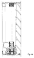
- Each of the sides 2-5 may also be composed of profiles, as indicated in fig. 4a and 4b.
- the four sides of the frame 1 may be assembled by means of weldings 6 or by appropriate connecting devices, such as screws and nuts or spikes.
- the ends of the sides 2-5 may be provided with cooperating grooves and tongues for mutual control of the ends, while the frame 1 may then be held together merely by inserting it into an opening, the dimensions of which correspond the outside measures of the frame 1.
- the frame 1 is adapted to be installed in the wall of a building having walls and/or roof of transparent material to the effect that the building can be heated by solar energy, and preferably the frame 1 should be of a length corresponding to the entire length of the wall, and the sheet member in the lower opening is usually placed with one of its long sides 3 parallel to the ground, preferably disposed against the ground or the foundation of the building.
- a curtain consisting of at least one layer 14 of windproof and flexible material of such dimension that the inside may be covered.
- This layer 14 is secured to the side of an edging 13 provided on the edge of the layer 14, which is secured as well to the sides of a number of lamellas or slats 11 having preferably a rectangular section and having their larger sides directed in transverse direction in relation to the plane of the frame 1.
- the slats 11 and the edging 13 are distributed at equal distances over the layer 14 and extend parallel with the long sides 2, 3 of the frame 1.
- the slats 11 are provided with recesses 12, which are formed to engage slidably with the controls 7, 8 to the effect that the slats 11 may be caused to move vertically within the plane of the frame.
- the edging 13 has notches corresponding to the recesses 12 at the ends of the slats, however the edging 13 is formed differently as compared to the slats 11 as will be described in detail below.
- the elastic layer 14 may for example be a woven fabric or a man-made material, only it must be pliable, when the distance between the slats 11 and the edging 13 decreases, or the slats are folded together face to face.
- the slats 11 and the edging 13 may also be provided with one or more perforations 15 evenly distributed over the lengths of the slats so that the frame, if made with a considerable length, may be fitted with additional controls for the slats 11 and the edging 13 within the plane of the frame and to absorb possible wind pressure against the layer 14.
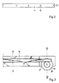
- these additional controls may be formed with teeth 9, 10. If so, the recesses 12 will be of rectangula shape. If the guides are without teeth, they will normally have a circular section, and so the perforations 15 will be circular as shown in fig. 2.
- the lower slat 11 is secured to one of the long sides 3 of the frame 1, for example by means of screws in perforations 15, which may not be utilized, or other appropriate openings, and it will be understood that a movement upwards of the edging 13 will cause the layer or the layers 14 to expand or stretch out so that the inside of the frame is covered, and that a movement of the edging 13 downwards will cause the layer or the layers 14 to fold, resulting in the maximum opening 32 possible between the edging 13 and the upper long side 2 of the frame 1, the inside of the opening 32 being defined alone by the possibility of folding together the slats 11 and the edging 13.
- the slats remain secured to the plane of the frame 1 by the interaction between the controls 7, 8 and the recesses 12 at the ends of the slats 11 and the mentioned notches of the edging 13.
- the edging 13 has a longitudinal channel 16 to receive the second rack bar 17, which is slidable in the longitudinal direction of the channel 16.
- the rack bar 17 is provided with teeth extending over a limited length at the ends of its edge or surface facing downwards.
- the notches extend further from the ends of the edging 13 than the recesses 12 of the slats 11.
- the notches thus are adapted to receive a drive wheel consisting of a first 19 and a second gear 20 of different sizes, mounted surface to surface and in mutual locked position on a shaft 28, which can be received rotatably in a bore 22 extending through the notch and at right angles to the plane of the frame 1.
- the bore 22 is placed in the edging 13 such that the first gear 19 having the larger diameter of the two gears 19, 20, can interact with the teeth 9, 10 of the controls 7, 8, and the second gear 20 can interact with the teeth 21 at the ends of the second rack bar 17.
- a movement by the second rack bar 17 in the channel 16 therefore, will cause the gear 20 and consequently the first gear 19 as well to rotate as a result of the interaction between the teeth 21 and the second gear 20.
- the controls 7, 8 should be mounted so that both teeth 9, 10 face the same end of the frame 1.
- the edging 13 has a longitudinal perforation 23 between the channel 16 and the side of the edging which is adapted to face the interior of the building when the frame 1 has been installed.
- This perforation 23 is of a length corresponding to the maximum movement possible of the second rack bar 17, and a corresponding perforation has been provided in the layer 14.
- the numerous channels and notches of the edging 13 can advantageously be effected by having the edging 13 consist of several layers of slats.
- the cylinder 24 has an inside piston and a piston rod 26 connected hereto extending out of the cylinder and is connected to the rack bar 17 with its free end, whereby the connection may have been provided by a stud extending from the piston rod through the perforation 23 into the rack bar 17.
- the hydraulic cylinder 24 is filled with a fluid having a rather high thermal expansion coefficient to the effect that the volume of the fluid may vary as much as possible concurrently with the variations of the fluid temperature.
- the inside piston mentioned is a so-called diving piston, which is to say that its cross section is considerably smaller that of the hydraulic cylinder 24.
- the piston rod 26 is sealed in a conventional manner in relation to the cylinder 24 by means of sealing devices, which are not illustrated in the drawing.
- the outside of the frame 1 is fitted with a grid 29 having horizontal openings 30 for admittance of the outside air into and through the frame 1.
- the grid 29 is provided with louvres 31 extending from the upper edge of each of the openings 30, and sloping downwards and outwards, and in addition the frame 1 may be provided with a fine-meshed net on either side, which is not illustrated in the drawing, in order to keep out insects.
- the sheet member according to the invention works in the following way: When rays of sunlight enter through the transparent material forming the walls and roof of the building, the temperature inside the building will increase.
- the fluid contained in the hydraulic cylinder 24 and the inside piston will warm up and expand to the effect that the piston rod 26 is pushed in a direction out of the cylinder.
- the second rack bar 17 will be included as well in the same direction in relation to the edging 13, and the teeth 21, as a result of their engagement with the second gear 20, and the intermediate reversing gears, if any, will cause the two first gears 19 to rotate to the effect that the edging 13 is moved downwards while still remaining parallel to the long sides 2, 3 of the frame 1.
- the curtain is folded together leaving an opening 32 between the upper long side 2 of the frame 1 and the edging 13.
- temperature detecting means have caused the second opening provided higher in the building to open to the effect that some of the heated air can escape.
- An air current is now created through the opening 32 of the frame 1, as a result of which the temperature will gradually assume a degree which is determined in part by the ventilation and in part by the intensity of the sunlight and a temperature of the fluid in the cylinder 24 corresponding hereto.
- the above described movements of the device is a comparatively slow process, and the device will find an opening 32 of reasonable size which will ensure maintenance of a predetermined temperature inside the building.
- the device When solar radiation ceases resulting in the temperature inside the building dropping below the predetermined level, the device will again close the opening 32.
Landscapes
- Engineering & Computer Science (AREA)
- Life Sciences & Earth Sciences (AREA)
- Mechanical Engineering (AREA)
- Chemical & Material Sciences (AREA)
- Sustainable Development (AREA)
- Combustion & Propulsion (AREA)
- Environmental Sciences (AREA)
- General Engineering & Computer Science (AREA)
- Greenhouses (AREA)
- Operating, Guiding And Securing Of Roll- Type Closing Members (AREA)
- Protection Of Plants (AREA)
- Manufacture Of Macromolecular Shaped Articles (AREA)
- Tents Or Canopies (AREA)
- Air-Flow Control Members (AREA)
Claims (4)
- Dispositif d'aération de bâtiments, en particulier jardins d'hiver, solariums et serres, comprenant un cadre rectangulaire (1) et au moins une couche (14) de matière résistant au vent qu'on peut faire coulisser au moyen d'un mécanisme de manoeuvre à détection de température (24,26) entre une position fermée, dans laquelle une ouverture du cadre (1) est entièrement fermée par la couche (14), et une position ouverte dans laquelle il y a un espace entre un premier côté (2) du cadre (1) et un premier bord de la couche (14) dont le deuxième bord opposé est étroitement relié à un deuxième côté (3) du cadre (1), ledit mécanisme de manoeuvre (24,26) étant monté sur une surface de la couche (14) qui est destinée à être tournée vers l'intérieur du bâtiment, caractérisé en ce que le cadre (1) porte au moins deux organes de commande (7,8) parallèles aux troisième et quatrième côtés (4,5) du cadre et fixés aux premier et deuxième côtés (2,3), en ce que la couche (14) est en une matière flexible et présente une surface fixée à plusieurs lamelles ou lattes (11,13) qui sont montées de façon équidistante parallèlement aux premier et deuxième côtés (2,3) du cadre, les dites lamelles ou lattes comportant des évidements (12) pour recevoir de façon coulissante les organes de commande (7,8), en ce que chaque organe de commande (7,8) est sous la forme d'une première crémaillère (9,10) qui engrène avec un premier pignon (19) bloqué contre un mouvement relatif par rapport à un deuxième pignon (20), et en ce que les premier (19) et deuxième (20) pignons sont montés de façontournante sur un arbre (28) prévu dans une des lattes de bord (13), le deuxième pignon (20) engrenant avec une deuxième crémaillère (17) disposée dans une rainure (16) de ladite latte de bord (13) portant le dit arbre (28), ladite deuxième crémaillère étant prévue pour être déplacée par le mécanisme de manoeuvre (24,26) dans sa direction longitudinale.
- Dispositif suivant la revendication 1, caractérisé en ce que le premier pignon (19) a un diamètre plus grand que celui du deuxième pignon (20).
- Dispositif suivant la revendication 1 ou 2, caractérisé en ce que le mécanisme de manoeuvre à détection de température (24,26) est un vérin hydraulique (24) qui est fixé à la latte de bord (13) portant l'arbre (28) et qui a un piston dont la section transversale est plus petite que celle du cylindre (24), et en ce que le piston comporte une tige de piston (26) qui est reliée à la deuxième crémaillère (17).
- Dispositif suivant la revendication 3, caractérisé en ce que le vérin hydraulique (24) est recouvert d'un écran.
Applications Claiming Priority (3)
| Application Number | Priority Date | Filing Date | Title |
|---|---|---|---|
| DK4431/89 | 1989-09-07 | ||
| DK443189A DK167086B1 (da) | 1989-09-07 | 1989-09-07 | Ventilationsorgan til ventilering af bygvaerker, isaer vinterhaver, udestuer og drivhuse |
| PCT/DK1990/000227 WO1991003153A1 (fr) | 1989-09-07 | 1990-08-31 | Procede servant a aerer des edifices tels que des jardins d'hiver, des solariums et des serres, et element a feuille utilise a cette fin |
Publications (2)
| Publication Number | Publication Date |
|---|---|
| EP0490948A1 EP0490948A1 (fr) | 1992-06-24 |
| EP0490948B1 true EP0490948B1 (fr) | 1994-07-27 |
Family
ID=8133458
Family Applications (1)
| Application Number | Title | Priority Date | Filing Date |
|---|---|---|---|
| EP90913471A Expired - Lifetime EP0490948B1 (fr) | 1989-09-07 | 1990-08-31 | Element à aérer des bâtiments tels que des jardins d'hiver, des solariums et des serres |
Country Status (7)
| Country | Link |
|---|---|
| US (1) | US5236124A (fr) |
| EP (1) | EP0490948B1 (fr) |
| AT (1) | ATE108976T1 (fr) |
| AU (1) | AU6356790A (fr) |
| DE (1) | DE69011121T2 (fr) |
| DK (1) | DK167086B1 (fr) |
| WO (1) | WO1991003153A1 (fr) |
Families Citing this family (7)
| Publication number | Priority date | Publication date | Assignee | Title |
|---|---|---|---|---|
| US6302785B1 (en) | 2000-06-12 | 2001-10-16 | Headrick Building Products, Inc. | Foundation vent with improved net free ventilation area |
| JP3948412B2 (ja) * | 2002-03-27 | 2007-07-25 | 株式会社デンソー | 空気通路開閉装置 |
| JP4321379B2 (ja) * | 2004-06-28 | 2009-08-26 | 株式会社デンソー | 空気通路開閉装置 |
| RU169358U1 (ru) * | 2016-07-25 | 2017-03-15 | Роман Александрович Усатов | Устройство для автоматического проветривания теплицы |
| RU171120U1 (ru) * | 2016-09-26 | 2017-05-22 | Роман Александрович Усатов | Устройство для автоматического проветривания теплицы |
| RU179718U1 (ru) * | 2017-07-06 | 2018-05-23 | Роман Александрович Усатов | Устройство для автоматического проветривания теплицы |
| RU179717U1 (ru) * | 2017-08-09 | 2018-05-23 | Роман Александрович Усатов | Устройство для автоматического проветривания теплицы |
Family Cites Families (9)
| Publication number | Priority date | Publication date | Assignee | Title |
|---|---|---|---|---|
| US589603A (en) * | 1897-09-07 | Robert william king | ||
| US1618792A (en) * | 1923-06-14 | 1927-02-22 | Wood Herbert James | Automatic ventilation-controlling apparatus |
| US1663352A (en) * | 1926-07-07 | 1928-03-20 | Saoutchik Jacques | Device for raising or lowering window panes |
| US1940191A (en) * | 1929-12-12 | 1933-12-19 | Charles Pressley Simonton | Opening and closing device for car doors |
| DE1043703B (de) * | 1957-05-29 | 1958-11-13 | Erich Blattert | Hydraulische Hubeinrichtung |
| DE2044821A1 (de) * | 1970-09-10 | 1972-03-16 | Badische Anilin- & Soda-Fabrik Ag, 6700 Ludwigshafen | Verfahren zur Anzucht von physiologisch und morphologisch hochwertigen Pflanzen in Gewächshäusern |
| US3669350A (en) * | 1970-12-11 | 1972-06-13 | Billy C White | Automatic temperature control apparatus for poultry houses and the like |
| GB1514586A (en) * | 1975-12-02 | 1978-06-14 | Baby Relax Ltd | Greenhouses |
| US4242833A (en) * | 1979-02-26 | 1981-01-06 | Environmental Research Institute Of Michigan | Greenhouse and method of growing plants in cold climates |
-
1989
- 1989-09-07 DK DK443189A patent/DK167086B1/da active
-
1990
- 1990-08-31 US US07/838,296 patent/US5236124A/en not_active Expired - Fee Related
- 1990-08-31 EP EP90913471A patent/EP0490948B1/fr not_active Expired - Lifetime
- 1990-08-31 AU AU63567/90A patent/AU6356790A/en not_active Abandoned
- 1990-08-31 AT AT90913471T patent/ATE108976T1/de not_active IP Right Cessation
- 1990-08-31 DE DE69011121T patent/DE69011121T2/de not_active Expired - Fee Related
- 1990-08-31 WO PCT/DK1990/000227 patent/WO1991003153A1/fr not_active Ceased
Also Published As
| Publication number | Publication date |
|---|---|
| DK443189D0 (da) | 1989-09-07 |
| DK443189A (da) | 1991-03-08 |
| DK167086B1 (da) | 1993-08-30 |
| DE69011121T2 (de) | 1995-01-26 |
| WO1991003153A1 (fr) | 1991-03-21 |
| ATE108976T1 (de) | 1994-08-15 |
| EP0490948A1 (fr) | 1992-06-24 |
| US5236124A (en) | 1993-08-17 |
| AU6356790A (en) | 1991-04-08 |
| DE69011121D1 (de) | 1994-09-01 |
Similar Documents
| Publication | Publication Date | Title |
|---|---|---|
| DE3737780C2 (de) | Gewächshaus | |
| DE4302883A1 (de) | Beschattungsvorrichtung für mit einer Verglasung versehene Fassaden- oder Dachelemente | |
| US5216834A (en) | Solar structure | |
| DE102005006329A1 (de) | Solaranlage | |
| US4228787A (en) | Solar heater, building cladding unit | |
| US5236124A (en) | Apparatus for automatically ventilating buildings such as winter gardens, sun lounges, and greenhouses | |
| CN109057617B (zh) | 一种可变建筑表皮系统 | |
| EP0164111B1 (fr) | Fenêtre composée insonorisante et calorifuge avec un dispositif d'aération | |
| US4452228A (en) | Solar air temperature control system for houses and other buildings | |
| DE2624646A1 (de) | Kombiniertes sonnenschutz- und energiegewinnungssystem | |
| DE4301008A1 (en) | Air conditioning plant for multi storey buildings - comprises blinds with upper slats being light reflecting and lower slats being light absorbing whose areas are varied by adjusting parting strip | |
| EP0044288B1 (fr) | Dispositif pour régler la radiation à travers des fenêtres | |
| EP0256441B1 (fr) | Elément de construction vitré | |
| EP0249919A2 (fr) | Arrangement d'une jalousie | |
| WO1989012205A1 (fr) | Collecteur solaire reglable a absorbeur parcouru par un fluide | |
| CN112314266A (zh) | 配备多段通风结构的塑料大棚 | |
| CN115362850B (zh) | 一种仿生内外循环的自动降温大棚 | |
| DE10115035B9 (de) | Niedrigenergiegebäude, insbesondere einergie-Autarkes Gebäude | |
| SU1740904A1 (ru) | Коллектор солнечной энергии | |
| DE9320324U1 (de) | Bedachung | |
| EP0003725B1 (fr) | Fenêtre à double vitrage, aérée dans le sens de la longueur et avec un store à l'intérieur | |
| EP2547966B1 (fr) | Façade et procédé de contrôle des propriétés thermiques de la façade | |
| DE2840024A1 (de) | Sonnenschutzeinrichtungen als sonnenkollektoren | |
| DE1008899B (de) | Wand- oder Dachverglasung | |
| CH686633A5 (de) | Oeffenbares Dachfenster. |
Legal Events
| Date | Code | Title | Description |
|---|---|---|---|
| PUAI | Public reference made under article 153(3) epc to a published international application that has entered the european phase |
Free format text: ORIGINAL CODE: 0009012 |
|
| 17P | Request for examination filed |
Effective date: 19920227 |
|
| AK | Designated contracting states |
Kind code of ref document: A1 Designated state(s): AT BE CH DE DK ES FR GB IT LI LU NL SE |
|
| 17Q | First examination report despatched |
Effective date: 19930927 |
|
| GRAA | (expected) grant |
Free format text: ORIGINAL CODE: 0009210 |
|
| AK | Designated contracting states |
Kind code of ref document: B1 Designated state(s): AT BE CH DE DK ES FR GB IT LI LU NL SE |
|
| PG25 | Lapsed in a contracting state [announced via postgrant information from national office to epo] |
Ref country code: IT Free format text: LAPSE BECAUSE OF FAILURE TO SUBMIT A TRANSLATION OF THE DESCRIPTION OR TO PAY THE FEE WITHIN THE PRE;WARNING: LAPSES OF ITALIAN PATENTS WITH EFFECTIVE DATE BEFORE 2007 MAY HAVE OCCURRED AT ANY TIME BEFORE 2007. THE CORRECT EFFECTIVE DATE MAY BE DIFFERENT FROM THE ONE RECORDED.SCRIBED TIME-LIMIT Effective date: 19940727 Ref country code: NL Effective date: 19940727 Ref country code: BE Effective date: 19940727 Ref country code: LI Effective date: 19940727 Ref country code: CH Effective date: 19940727 Ref country code: ES Free format text: THE PATENT HAS BEEN ANNULLED BY A DECISION OF A NATIONAL AUTHORITY Effective date: 19940727 Ref country code: AT Effective date: 19940727 Ref country code: DK Effective date: 19940727 |
|
| REF | Corresponds to: |
Ref document number: 108976 Country of ref document: AT Date of ref document: 19940815 Kind code of ref document: T |
|
| PG25 | Lapsed in a contracting state [announced via postgrant information from national office to epo] |
Ref country code: LU Free format text: LAPSE BECAUSE OF NON-PAYMENT OF DUE FEES Effective date: 19940831 |
|
| REF | Corresponds to: |
Ref document number: 69011121 Country of ref document: DE Date of ref document: 19940901 |
|
| PG25 | Lapsed in a contracting state [announced via postgrant information from national office to epo] |
Ref country code: SE Effective date: 19941027 |
|
| REG | Reference to a national code |
Ref country code: CH Ref legal event code: PL |
|
| ET | Fr: translation filed | ||
| NLV1 | Nl: lapsed or annulled due to failure to fulfill the requirements of art. 29p and 29m of the patents act | ||
| PLBE | No opposition filed within time limit |
Free format text: ORIGINAL CODE: 0009261 |
|
| STAA | Information on the status of an ep patent application or granted ep patent |
Free format text: STATUS: NO OPPOSITION FILED WITHIN TIME LIMIT |
|
| 26N | No opposition filed | ||
| PGFP | Annual fee paid to national office [announced via postgrant information from national office to epo] |
Ref country code: GB Payment date: 19970822 Year of fee payment: 8 |
|
| PGFP | Annual fee paid to national office [announced via postgrant information from national office to epo] |
Ref country code: FR Payment date: 19970826 Year of fee payment: 8 |
|
| PG25 | Lapsed in a contracting state [announced via postgrant information from national office to epo] |
Ref country code: GB Free format text: LAPSE BECAUSE OF NON-PAYMENT OF DUE FEES Effective date: 19980831 |
|
| GBPC | Gb: european patent ceased through non-payment of renewal fee |
Effective date: 19980831 |
|
| PG25 | Lapsed in a contracting state [announced via postgrant information from national office to epo] |
Ref country code: FR Free format text: LAPSE BECAUSE OF NON-PAYMENT OF DUE FEES Effective date: 19990430 |
|
| REG | Reference to a national code |
Ref country code: FR Ref legal event code: ST |
|
| PGFP | Annual fee paid to national office [announced via postgrant information from national office to epo] |
Ref country code: DE Payment date: 20000819 Year of fee payment: 11 |
|
| PG25 | Lapsed in a contracting state [announced via postgrant information from national office to epo] |
Ref country code: DE Free format text: LAPSE BECAUSE OF NON-PAYMENT OF DUE FEES Effective date: 20020501 |