EP0491082A1 - Conduit de stimulateur cardiaque avec un canal intérieur et une tête d'électrode - Google Patents
Conduit de stimulateur cardiaque avec un canal intérieur et une tête d'électrode Download PDFInfo
- Publication number
- EP0491082A1 EP0491082A1 EP90124817A EP90124817A EP0491082A1 EP 0491082 A1 EP0491082 A1 EP 0491082A1 EP 90124817 A EP90124817 A EP 90124817A EP 90124817 A EP90124817 A EP 90124817A EP 0491082 A1 EP0491082 A1 EP 0491082A1
- Authority
- EP
- European Patent Office
- Prior art keywords
- pacemaker lead
- electrode head
- coupling
- cavity
- projection
- Prior art date
- Legal status (The legal status is an assumption and is not a legal conclusion. Google has not performed a legal analysis and makes no representation as to the accuracy of the status listed.)
- Granted
Links
- 230000008878 coupling Effects 0.000 claims abstract description 39
- 238000010168 coupling process Methods 0.000 claims abstract description 39
- 238000005859 coupling reaction Methods 0.000 claims abstract description 39
- 238000007373 indentation Methods 0.000 claims description 9
- 230000033001 locomotion Effects 0.000 claims description 9
- 210000005003 heart tissue Anatomy 0.000 claims description 8
- 210000001519 tissue Anatomy 0.000 claims description 7
- 238000010438 heat treatment Methods 0.000 claims description 6
- 239000002184 metal Substances 0.000 claims description 6
- 230000000747 cardiac effect Effects 0.000 claims description 5
- 239000003814 drug Substances 0.000 claims description 5
- 229940079593 drug Drugs 0.000 claims description 4
- 230000013011 mating Effects 0.000 claims description 2
- 238000002513 implantation Methods 0.000 abstract description 3
- 238000004873 anchoring Methods 0.000 description 11
- 241000209035 Ilex Species 0.000 description 4
- 230000006870 function Effects 0.000 description 2
- 241001463014 Chazara briseis Species 0.000 description 1
- 230000005540 biological transmission Effects 0.000 description 1
- 230000008094 contradictory effect Effects 0.000 description 1
- 230000009977 dual effect Effects 0.000 description 1
- 208000015181 infectious disease Diseases 0.000 description 1
- 238000003780 insertion Methods 0.000 description 1
- 230000037431 insertion Effects 0.000 description 1
- 238000012986 modification Methods 0.000 description 1
- 230000004048 modification Effects 0.000 description 1
- 210000002023 somite Anatomy 0.000 description 1
- 238000001356 surgical procedure Methods 0.000 description 1
Images


Classifications
-
- A—HUMAN NECESSITIES
- A61—MEDICAL OR VETERINARY SCIENCE; HYGIENE
- A61N—ELECTROTHERAPY; MAGNETOTHERAPY; RADIATION THERAPY; ULTRASOUND THERAPY
- A61N1/00—Electrotherapy; Circuits therefor
- A61N1/02—Details
- A61N1/04—Electrodes
- A61N1/05—Electrodes for implantation or insertion into the body, e.g. heart electrode
- A61N1/056—Transvascular endocardial electrode systems
- A61N1/057—Anchoring means; Means for fixing the head inside the heart
- A61N1/0573—Anchoring means; Means for fixing the head inside the heart chacterised by means penetrating the heart tissue, e.g. helix needle or hook
Definitions
- the invention relates to a pacemaker lead with an inner channel for a stylet or the like and with an electrode head that can be fixed inside the heart, for example a screw spiral that can be screwed into the tissue.
- Implantable pacemaker leads with anchored electrode heads are known in various forms, for example with the screw spirals already mentioned or with hooking bristle-like pins, umbrella-like cone bodies or the like.
- a pacemaker lead of the type mentioned at the outset is described in DE-A-2539 553, a screw helix serving to anchor the electrode head.
- the screwing movement can be carried out with the help of a stylet that can be pushed through the inner channel.
- a modified anchoring of an electrode head is known from DE-B-31 46 182.
- the surprising solution to this apparently contradictory task is that at the distal end of the pacemaker lead there is a cavity associated with or adjacent to the electrode head, which is accessible or open in the axial direction from the proximal end of the pacemaker lead and a coupling for one from the proximal end of the pacemaker lead insertable traction element or stiletto. If such a pacemaker lead and, above all, its electrode head has to be pulled out of the heart, a pulling element or stylet can be inserted from the proximal end into the pacemaker lead through its inner channel and preferably connected to the coupling of the cavity at the distal end, so that the tensile forces required for removal can be applied practically directly to the anchorage and to the electrode head itself. It is therefore not necessary to transmit these tensile forces via the supply line of the pacemaker lead, which is relatively flexible in the axial direction, and the danger is avoided that this supply line is separated from the actual electrode head and its anchoring when such tensile forces are applied.
- a particularly expedient embodiment of the invention can consist in that the cavity arranged in the region of the electrode head has at least one protrusion protruding into its interior or an undercut and that the stylet or pulling element has a counterpart fitting behind the protrusion or in the undercut and by rotating with it this projection or the like can be coupled.
- the stylet or another traction element For pulling out the electrode head It is therefore sufficient to advance the stylet or another traction element through the inner channel of the supply line into the cavity, to fix it there in a form-fitting manner by rotating it in the axial direction, in order to then be able to apply the desired traction force directly where it is needed.
- At least one indentation or similar eccentric projection can be provided as an inwardly projecting projection in the cavity, and the pulling element can have as a counterpart a coupling head that can be pushed on the projection in one direction of rotation and engages behind the projection by rotation.
- Such coupling counterparts in the shape of an angle or hammer head are simple to produce and less prone to failure, but at the same time are very effective.
- the stiletto or pulling element can also have a flattened, indented, head as a counterpart, which can be pushed past the inner projection of the cavity in one direction of rotation and then with the indentation, recess or indentation the projection inside with its indentation, recess or indentation of the cavity.
- the tension element consists of memory metal at least in its coupling area and, after passing the preferably annular coupling projection, engages behind this projection on its distal side by heating.
- the body heat or preferably a coupling of the tension element consisting of wire or the like to a power source can be provided for heating the memory metal.
- the cavity having the coupling for the tension element can be designed as a sleeve arranged in the distal end region of the insulating covering of the pacemaker lead, to the distal end of which the actual electrode head, preferably a screw-in helix, is attached.
- a sleeve is expedient when inserting the pacemaker lead, because a stylet for advancing the pacemaker lead and its electrode head can find a good abutment in it, and the necessary force and movement for anchoring, for example a rotary movement for a screw-in helix, can be transmitted well and at the same time there is also a tensile connection between this sleeve and the actual armature part of the electrode head.
- This sleeve can thus serve a dual function as a cavity, namely, on the one hand, it facilitates implantation and anchoring as well as the transmission of stimuli, but it can also be used to retract the electrode head, because a recess that serves as a coupling projection can be conveniently attached to such a sleeve.
- the rotary movement used to produce the coupling between the tension element and the electrode head has the opposite direction of rotation as is provided for screwing the screw helix into the tissue. If the coupling between the tension element and the cavity is produced in this form, it is, in a way, additional already a rotary motion is applied to the screw coil, which could be released from its anchoring position if it is not overgrown, ie the rotary motion when the tension element is coupled to the electrode head acts on the screw coil in its release direction.
- a further advantageous use of the cavity with a coupling for a tension element can consist in that an opening for dispensing a medicament to the heart tissue is provided at the distal end of the coupling cavity.
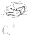
- a cardiac pacemaker lead designated as a whole, has a lead 2, which can be made up of individual turns in a spiral shape and an insulating one Hose 3 can be covered.
- the lead 2 connects a pacemaker 4 to an electrode head 6 which can be anchored in the interior of the heart 5 and which can be designed differently according to FIGS. 2 and 3 or 5 and 6 or 8, further modifications of this electrode head 6 being possible .
- the electrode head 6 has a screw helix 7 that can be screwed into the tissue for anchoring it.
- the electrode heads 6 according to FIGS. 5 and 6 and 8 can get caught with a holding edge 8 within the heart tissue.
- All of the exemplary embodiments have in common that at the distal end of the pacemaker lead 1 there is a cavity 9 which is associated or adjacent to the electrode head 6 and which is accessible or open in the axial direction from the proximal end of the pacemaker lead and one to be described in detail in the exemplary embodiments Coupling for a pulling element or stylet 10 insertable from the proximal end of the pacemaker lead 1.
- the cavity 9 arranged in the region of the electrode head 6 can have at least one, in the exemplary embodiment according to FIGS.
- the stylet 10 which is used to apply a tensile force when removing the electrode head 6 to be inserted from the heart 5 has a counterpart 12 which fits behind the one or more projections 11 and which can be fixed and coupled by turning, in which tensile forces are then transmitted to the electrode head 6 via the stylet 10 can.
- Fig. 2 you can first see a conventional stylet, which fits between the two projections 11 and for screwing the screw 7 in the heart tissue serves.
- the flat head of the stylet is so long that it extends from the distal end of the cavity 9 over the projections 11.
- the stylet 10 serving as a pulling element is provided with a shorter head 12 which, after insertion, can be rotated as far as the distal end or the end wall 13 of the cavity 9 such that, according to FIG. 3, this widened head has the projections 11 engages behind and now forms a tensile coupling.
- Fig. 4 shows that when the stylet 10 is inserted with the widened head 12 in one orientation direction, this flattened head 12 can be easily pushed between the projections 11, after which it can be rotated by approximately 90 ° in order to achieve the 3 apparent position of use for the application of a withdrawal force.
- the inwardly projecting projections 11 are indentations, past which the coupling head 12 of the stylet 10 can be pushed, after which it can be coupled by rotation in the manner already mentioned.
- threads protrude into the cavity 9 and the pulling element or stylet 10 has a matching counterthread 14 at its distal end, which thread can therefore be coupled to the cavity 9 by rotation.
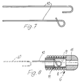
- the tension element consists at least in its coupling area of memory metal and is initially bent in a U-shape in this coupling area in such a way that it can be inserted into an enlarged area of the cavity 9 through the annular coupling projection 11 of this embodiment is.
- the coupling end of this tension element then deforms in the manner shown to form a loop which engages behind the annular coupling projection 11 in the interior of the cavity 9, so that a high tensile force can again be exerted directly on the electrode head 6 in this case.
- the cavity 9, which has the coupling for the pulling element is designed in all these exemplary embodiments as a sleeve arranged in the distal end region of the insulating cover or tube 3 of the pacemaker lead 1, to the distal end of which the actual electrode head or the screw-in helix 7 is fastened .
- This sleeve thus has a double function, because on the one hand it bears the anchoring of the electrode head 6 and on the other hand it forms the cavity with the coupling projection for the tension element or stiletto 10.
- an opening 15 for delivering a drug to the heart tissue can be seen, which drug can be stored in the cavity 9 or fed through the inner channel 16 of the lead 2 of the pacemaker lead 1 can be.
- Such an opening or a smaller opening 15 could also be provided on the front wall 13 of the sleeve for the cavity 11 according to FIGS. 2 and 3 in order to gradually release a medication into the heart.
- the pacemaker lead 1 with a lead 2 between a pacemaker 4 and an electrode head 6 for implantation in the tissue of the heart 5 and an inner channel 16 for a stylet or the like has at the distal end a cavity 9 belonging to the electrode head 6, which extends in the axial direction from proximal end of the pacemaker lead 1 is accessible and open through the channel 16 and has a coupling for a pulling element or stylet 10 which can be inserted from the proximal end, so that the anchoring of the electrode head 6 can be released if necessary by a pulling force applied directly to it, So there is no risk of tearing in the course of the feed line 2 or at its connection to the electrode head 6.
- Different possibilities for designing the coupling are preferably possible with projections 11 projecting into the interior of the cavity 9, with which a corresponding counterpart 12 on the pulling element or stylet 10 can be brought into operative connection, above all by rotation.
Landscapes
- Health & Medical Sciences (AREA)
- Cardiology (AREA)
- Heart & Thoracic Surgery (AREA)
- Vascular Medicine (AREA)
- Engineering & Computer Science (AREA)
- Biomedical Technology (AREA)
- Nuclear Medicine, Radiotherapy & Molecular Imaging (AREA)
- Radiology & Medical Imaging (AREA)
- Life Sciences & Earth Sciences (AREA)
- Animal Behavior & Ethology (AREA)
- General Health & Medical Sciences (AREA)
- Public Health (AREA)
- Veterinary Medicine (AREA)
- Electrotherapy Devices (AREA)
Priority Applications (4)
| Application Number | Priority Date | Filing Date | Title |
|---|---|---|---|
| DE59008908T DE59008908D1 (de) | 1990-12-19 | 1990-12-19 | Herzschrittmacherleitung mit einem inneren Kanal und mit einem Elektrodenkopf. |
| EP90124817A EP0491082B1 (fr) | 1990-12-19 | 1990-12-19 | Conduit de stimulateur cardiaque avec un canal intérieur et une tête d'électrode |
| AT90124817T ATE120971T1 (de) | 1990-12-19 | 1990-12-19 | Herzschrittmacherleitung mit einem inneren kanal und mit einem elektrodenkopf. |
| US07/795,006 US5261419A (en) | 1990-12-19 | 1991-11-15 | Cardiac pacemaker lead |
Applications Claiming Priority (1)
| Application Number | Priority Date | Filing Date | Title |
|---|---|---|---|
| EP90124817A EP0491082B1 (fr) | 1990-12-19 | 1990-12-19 | Conduit de stimulateur cardiaque avec un canal intérieur et une tête d'électrode |
Publications (2)
| Publication Number | Publication Date |
|---|---|
| EP0491082A1 true EP0491082A1 (fr) | 1992-06-24 |
| EP0491082B1 EP0491082B1 (fr) | 1995-04-12 |
Family
ID=8204869
Family Applications (1)
| Application Number | Title | Priority Date | Filing Date |
|---|---|---|---|
| EP90124817A Expired - Lifetime EP0491082B1 (fr) | 1990-12-19 | 1990-12-19 | Conduit de stimulateur cardiaque avec un canal intérieur et une tête d'électrode |
Country Status (4)
| Country | Link |
|---|---|
| US (1) | US5261419A (fr) |
| EP (1) | EP0491082B1 (fr) |
| AT (1) | ATE120971T1 (fr) |
| DE (1) | DE59008908D1 (fr) |
Cited By (3)
| Publication number | Priority date | Publication date | Assignee | Title |
|---|---|---|---|---|
| US5374287A (en) * | 1991-04-10 | 1994-12-20 | British Technology Group Usa Inc. | Defibrillator and demand pacer catheters and methods for using same |
| FR2733429A1 (fr) * | 1995-04-28 | 1996-10-31 | Dev Sed Soc Et | Dispositif de maniement et de mise en place d'une electrode d'appareil de stimulation cardiaque |
| US5851227A (en) * | 1997-07-30 | 1998-12-22 | Sulzer Intermedics Inc. | Cardiac pacemaker cable lead |
Families Citing this family (47)
| Publication number | Priority date | Publication date | Assignee | Title |
|---|---|---|---|---|
| US5769858A (en) * | 1995-10-20 | 1998-06-23 | Medtronic, Inc. | Locking stylet for extracting implantable lead or catheter |
| US5755762A (en) * | 1996-06-14 | 1998-05-26 | Pacesetter, Inc. | Medical lead and method of making and using |
| US5851226A (en) * | 1996-10-22 | 1998-12-22 | Medtronic, Inc. | Temporary transvenous endocardial lead |
| US6501993B2 (en) | 2001-03-27 | 2002-12-31 | Pacesetter, Inc. | Electrode assembly with a detachable distal tip |
| EP2075014B9 (fr) | 2002-05-24 | 2012-02-01 | Angiotech International Ag | Compositions et procédés pour le revêtement d'implants médicaux |
| US6944506B1 (en) * | 2002-06-25 | 2005-09-13 | Pacesetter, Inc. | Stylet feature for resisting perforation of an implantable lead |
| US7103418B2 (en) * | 2002-10-02 | 2006-09-05 | Medtronic, Inc. | Active fluid delivery catheter |
| FR2846639B1 (fr) * | 2002-11-06 | 2004-12-10 | Innovation Packaging | Dispositif de conditionnement et de distribution pour un produit liquide ou semi-liquide |
| WO2004043518A2 (fr) * | 2002-11-07 | 2004-05-27 | Axiom Medical Inc. | Sonde cardiaque epicardique, drain thoracique avec sonde cardiaque epicardique et procede d'utilisation |
| US7962208B2 (en) | 2005-04-25 | 2011-06-14 | Cardiac Pacemakers, Inc. | Method and apparatus for pacing during revascularization |
| US9006487B2 (en) | 2005-06-15 | 2015-04-14 | Massachusetts Institute Of Technology | Amine-containing lipids and uses thereof |
| US8019438B2 (en) * | 2005-06-28 | 2011-09-13 | Cardiac Pacemakers, Inc. | Anchor for electrode delivery system |
| US20070055334A1 (en) * | 2005-08-23 | 2007-03-08 | Cardiac Pacemakers, Inc. | Cardiac lead and stylet assembly |
| US7885710B2 (en) | 2005-12-23 | 2011-02-08 | Cardiac Pacemakers, Inc. | Method and apparatus for tissue protection against ischemia using remote conditioning |
| US8918193B2 (en) * | 2006-08-16 | 2014-12-23 | Vahe S. Yacoubian | Heart wire |
| US8457738B2 (en) | 2008-06-19 | 2013-06-04 | Cardiac Pacemakers, Inc. | Pacing catheter for access to multiple vessels |
| US8244352B2 (en) | 2008-06-19 | 2012-08-14 | Cardiac Pacemakers, Inc. | Pacing catheter releasing conductive liquid |
| US9037235B2 (en) | 2008-06-19 | 2015-05-19 | Cardiac Pacemakers, Inc. | Pacing catheter with expandable distal end |
| US9409012B2 (en) | 2008-06-19 | 2016-08-09 | Cardiac Pacemakers, Inc. | Pacemaker integrated with vascular intervention catheter |
| US8639357B2 (en) | 2008-06-19 | 2014-01-28 | Cardiac Pacemakers, Inc. | Pacing catheter with stent electrode |
| WO2010002456A1 (fr) * | 2008-07-01 | 2010-01-07 | Cardiac Pacemakers, Inc. | Dispositif de commande de système de stimulation intégré dans un gonfleur-dégonfleur |
| ES2646630T3 (es) | 2008-11-07 | 2017-12-14 | Massachusetts Institute Of Technology | Lipidoides aminoalcohólicos y usos de los mismos |
| US20110106099A1 (en) * | 2009-10-29 | 2011-05-05 | Medtronic, Inc. | Lead extraction device |
| HUE042177T2 (hu) | 2009-12-01 | 2019-06-28 | Translate Bio Inc | Szteroidszármazék mRNS szállítására humán genetikai betegségekben |
| EP2609135A4 (fr) | 2010-08-26 | 2015-05-20 | Massachusetts Inst Technology | Poly(bêta-amino-alcools), leur préparation et utilisations de ceux-ci |
| US9238716B2 (en) | 2011-03-28 | 2016-01-19 | Massachusetts Institute Of Technology | Conjugated lipomers and uses thereof |
| PL3586861T3 (pl) | 2011-06-08 | 2022-05-23 | Translate Bio, Inc. | Kompozycje nanocząstek lipidowych i sposoby dostarczania mrna |
| EP3536787A1 (fr) | 2012-06-08 | 2019-09-11 | Translate Bio, Inc. | Polynucléotides résistant aux nucléases et leurs utilisations |
| PL3467108T3 (pl) | 2013-03-14 | 2024-09-30 | Translate Bio, Inc. | Sposoby oczyszczania informacyjnego rna |
| KR20210122917A (ko) | 2013-03-14 | 2021-10-12 | 샤이어 휴먼 지네틱 테라피즈 인크. | Cftr mrna 조성물 및 관련 방법 및 사용 |
| WO2014179562A1 (fr) | 2013-05-01 | 2014-11-06 | Massachusetts Institute Of Technology | Dérivés de 1,3,5-triazinane-2,4,6-trione et leurs utilisations |
| EA034103B1 (ru) | 2013-10-22 | 2019-12-27 | Транслейт Био, Инк. | СПОСОБ ЛЕЧЕНИЯ ФЕНИЛКЕТОНУРИИ С ПРИМЕНЕНИЕМ мРНК |
| ES2707966T3 (es) | 2013-10-22 | 2019-04-08 | Translate Bio Inc | Terapia de ARNm para la deficiencia en síntesis de argininosuccinato |
| MX2016005238A (es) | 2013-10-22 | 2016-08-12 | Shire Human Genetic Therapies | Formulaciones de lipidos para la administracion de acido ribonucleico mensajero. |
| PT3134506T (pt) | 2014-04-25 | 2019-10-31 | Translate Bio Inc | Métodos de purificação de rna mensageiro |
| JP6557722B2 (ja) | 2014-05-30 | 2019-08-07 | シャイアー ヒューマン ジェネティック セラピーズ インコーポレイテッド | 核酸の送達のための生分解性脂質 |
| EP3160959B1 (fr) | 2014-06-24 | 2023-08-30 | Translate Bio, Inc. | Compositions enrichies stéréochimiquement pour l'administration d'acides nucléiques |
| US9840479B2 (en) | 2014-07-02 | 2017-12-12 | Massachusetts Institute Of Technology | Polyamine-fatty acid derived lipidoids and uses thereof |
| EA201991747A1 (ru) | 2017-02-27 | 2020-06-04 | Транслейт Био, Инк. | НОВАЯ КОДОН-ОПТИМИЗИРОВАННАЯ мРНК CFTR |
| MX2019013752A (es) | 2017-05-16 | 2020-07-20 | Translate Bio Inc | Tratamiento de la fibrosis quística mediante el suministro de arnm que codifica cftr optimizado en codones. |
| US11865334B2 (en) | 2017-08-21 | 2024-01-09 | MRM MedTech, LLC | Lead with integrated feature including a low friction component to facilitate extraction and associated methods of extraction |
| US10933247B2 (en) | 2017-08-21 | 2021-03-02 | MRM MedTech, LLC | Lead with integrated features to facilitate extraction and associated methods of extraction |
| CA3108544A1 (fr) | 2018-08-24 | 2020-02-27 | Translate Bio, Inc. | Procedes de purification d'arn messager |
| KR102137740B1 (ko) * | 2018-11-15 | 2020-07-24 | (주) 타우피엔유메디칼 | 서클라지 심박동기 리드 |
| MX2021005969A (es) | 2018-11-21 | 2021-09-14 | Translate Bio Inc | Tratamiento de la fibrosis quística mediante el suministro de arnm que codifica cftr nebulizado. |
| CN109568793B (zh) * | 2018-12-25 | 2023-08-04 | 创领心律管理医疗器械(上海)有限公司 | 无导线起搏器及无导线起搏系统 |
| KR102755550B1 (ko) * | 2019-11-05 | 2025-01-21 | 보스톤 싸이엔티픽 싸이메드 인코포레이티드 | 조직 포획 나선형 디바이스 |
Citations (3)
| Publication number | Priority date | Publication date | Assignee | Title |
|---|---|---|---|---|
| EP0047013A1 (fr) * | 1980-09-02 | 1982-03-10 | Medtronic, Inc. | Conducteur implantable de façon sous-cutanée comprenant des moyens pour delivrer un medicament |
| EP0282047A2 (fr) * | 1987-03-13 | 1988-09-14 | Hans-Jürgen Dipl.-Ing. Bisping | Sonde implantable à électrode en spirale extractible |
| EP0368568A2 (fr) * | 1988-11-09 | 1990-05-16 | Med Institute, Inc. | Appareil pour retirer un élément longiforme implanté dans un tissu biologique |
Family Cites Families (5)
| Publication number | Priority date | Publication date | Assignee | Title |
|---|---|---|---|---|
| DE2539553A1 (de) * | 1975-09-05 | 1977-03-10 | Osypka Peter | Elektrodenanordnung fuer medizinische zwecke |
| USRE32227E (en) * | 1981-03-19 | 1986-08-19 | Medtronic, Inc. | "J" Stylet wire |
| DE3146182C2 (de) * | 1981-11-21 | 1984-03-29 | Peter Dr. 7889 Grenzach-Wyhlen Osypka | Transvenös ins Herz einführbare Elektrodenanordnung für einen Herzschrittmacher |
| US4924881A (en) * | 1989-05-12 | 1990-05-15 | Intermedics, Inc. | Implantable endocardial lead with fixation device retractable by threaded stylet |
| US5003992A (en) * | 1989-08-23 | 1991-04-02 | Holleman Timothy W | Atraumatic screw-in lead |
-
1990
- 1990-12-19 AT AT90124817T patent/ATE120971T1/de active
- 1990-12-19 EP EP90124817A patent/EP0491082B1/fr not_active Expired - Lifetime
- 1990-12-19 DE DE59008908T patent/DE59008908D1/de not_active Expired - Fee Related
-
1991
- 1991-11-15 US US07/795,006 patent/US5261419A/en not_active Expired - Fee Related
Patent Citations (3)
| Publication number | Priority date | Publication date | Assignee | Title |
|---|---|---|---|---|
| EP0047013A1 (fr) * | 1980-09-02 | 1982-03-10 | Medtronic, Inc. | Conducteur implantable de façon sous-cutanée comprenant des moyens pour delivrer un medicament |
| EP0282047A2 (fr) * | 1987-03-13 | 1988-09-14 | Hans-Jürgen Dipl.-Ing. Bisping | Sonde implantable à électrode en spirale extractible |
| EP0368568A2 (fr) * | 1988-11-09 | 1990-05-16 | Med Institute, Inc. | Appareil pour retirer un élément longiforme implanté dans un tissu biologique |
Cited By (5)
| Publication number | Priority date | Publication date | Assignee | Title |
|---|---|---|---|---|
| US5374287A (en) * | 1991-04-10 | 1994-12-20 | British Technology Group Usa Inc. | Defibrillator and demand pacer catheters and methods for using same |
| US5476502A (en) * | 1991-04-10 | 1995-12-19 | British Technology Group Usa Inc. | Defibrillator and demand pacer catheters and methods for using same |
| FR2733429A1 (fr) * | 1995-04-28 | 1996-10-31 | Dev Sed Soc Et | Dispositif de maniement et de mise en place d'une electrode d'appareil de stimulation cardiaque |
| EP0740943A1 (fr) * | 1995-04-28 | 1996-11-06 | Societe Etudes Et Developpements S.E.D. | Dispositif de maniement et de mise en place d'une électrode d'appareil de stimulation cardiaque |
| US5851227A (en) * | 1997-07-30 | 1998-12-22 | Sulzer Intermedics Inc. | Cardiac pacemaker cable lead |
Also Published As
| Publication number | Publication date |
|---|---|
| ATE120971T1 (de) | 1995-04-15 |
| EP0491082B1 (fr) | 1995-04-12 |
| DE59008908D1 (de) | 1995-05-18 |
| US5261419A (en) | 1993-11-16 |
Similar Documents
| Publication | Publication Date | Title |
|---|---|---|
| EP0491082B1 (fr) | Conduit de stimulateur cardiaque avec un canal intérieur et une tête d'électrode | |
| EP0792129B1 (fr) | Prothese articulaire modulaire | |
| EP0348692B1 (fr) | Dispositif pour l'introduction transveneuse ou artérielle a moyen d'un fil guide | |
| DE69624008T2 (de) | Flacher marknagel | |
| EP0513943B1 (fr) | Implant avec surface de pression | |
| EP0592897B1 (fr) | Modulaire pour une prothèse de la hanche | |
| DE69519732T2 (de) | Knochenschraube mit reversibler Verschluss | |
| DE10316177B4 (de) | Herzschrittmacher-Elektrodenanordnung | |
| EP0795344B1 (fr) | Dispositif implantable | |
| DE69927398T2 (de) | Vorderseitige laterale plattenförmige wirbelsäulenbefestigungsvorrichtung und ihre technik | |
| DE1054659B (de) | Rohrfoermiger Knochennagel | |
| DE2112138B1 (de) | Huelsenfoermiges Stuetzelement fuer Roehrenknochenfrakturen | |
| EP1321165A2 (fr) | Electrode épicardique, cathéter et dispositif d'implantation correspondants | |
| DE3146182C2 (de) | Transvenös ins Herz einführbare Elektrodenanordnung für einen Herzschrittmacher | |
| AT395940B (de) | Knochennagel und werkzeug fuer denselben | |
| DE2755179A1 (de) | Vorrichtung zum ansetzen eines messkopfes | |
| EP2281600A1 (fr) | Dispositif de défibrillation d'un coeur | |
| DE102006026590B3 (de) | Implantat | |
| DE202005022017U1 (de) | Knochenanker mit zur Fixierung in kortikalem Knochengewebe und Spongiosa-Gewebe optimierter Gewindestruktur | |
| DE2533766A1 (de) | Transvenoese, implantierbare herzschrittmacherelektrode | |
| EP1064885A1 (fr) | Fixateur rachidien | |
| EP0219608A2 (fr) | Conducteur de stimulateur cardiaque introduit par voie veineuse | |
| DE102008005378B4 (de) | Implantierbare bipolare Elektrode | |
| WO2002080790A1 (fr) | Broche a usage chirurgical | |
| DE102008005377A1 (de) | Bipolare Elektrode |
Legal Events
| Date | Code | Title | Description |
|---|---|---|---|
| PUAI | Public reference made under article 153(3) epc to a published international application that has entered the european phase |
Free format text: ORIGINAL CODE: 0009012 |
|
| 17P | Request for examination filed |
Effective date: 19911004 |
|
| AK | Designated contracting states |
Kind code of ref document: A1 Designated state(s): AT CH DE ES FR GB IT LI NL SE |
|
| 17Q | First examination report despatched |
Effective date: 19940201 |
|
| GRAA | (expected) grant |
Free format text: ORIGINAL CODE: 0009210 |
|
| AK | Designated contracting states |
Kind code of ref document: B1 Designated state(s): AT CH DE ES FR GB IT LI NL SE |
|
| PG25 | Lapsed in a contracting state [announced via postgrant information from national office to epo] |
Ref country code: ES Free format text: THE PATENT HAS BEEN ANNULLED BY A DECISION OF A NATIONAL AUTHORITY Effective date: 19950412 |
|
| REF | Corresponds to: |
Ref document number: 120971 Country of ref document: AT Date of ref document: 19950415 Kind code of ref document: T |
|
| REF | Corresponds to: |
Ref document number: 59008908 Country of ref document: DE Date of ref document: 19950518 |
|
| ITF | It: translation for a ep patent filed | ||
| GBT | Gb: translation of ep patent filed (gb section 77(6)(a)/1977) |
Effective date: 19950612 |
|
| PG25 | Lapsed in a contracting state [announced via postgrant information from national office to epo] |
Ref country code: SE Effective date: 19950712 |
|
| ET | Fr: translation filed | ||
| PLBI | Opposition filed |
Free format text: ORIGINAL CODE: 0009260 |
|
| PLBF | Reply of patent proprietor to notice(s) of opposition |
Free format text: ORIGINAL CODE: EPIDOS OBSO |
|
| 26 | Opposition filed |
Opponent name: BIOTRONIK MESS- UND THERAPIEGERAETE GMBH & CO INGE Effective date: 19960108 |
|
| PLBF | Reply of patent proprietor to notice(s) of opposition |
Free format text: ORIGINAL CODE: EPIDOS OBSO |
|
| NLR1 | Nl: opposition has been filed with the epo |
Opponent name: BIOTRONIK MESS- UND THERAPIEGERAETE GMBH & CO INGE |
|
| PLBQ | Unpublished change to opponent data |
Free format text: ORIGINAL CODE: EPIDOS OPPO |
|
| PGFP | Annual fee paid to national office [announced via postgrant information from national office to epo] |
Ref country code: FR Payment date: 19981013 Year of fee payment: 9 |
|
| PGFP | Annual fee paid to national office [announced via postgrant information from national office to epo] |
Ref country code: DE Payment date: 19981028 Year of fee payment: 9 |
|
| PGFP | Annual fee paid to national office [announced via postgrant information from national office to epo] |
Ref country code: GB Payment date: 19981215 Year of fee payment: 9 |
|
| PGFP | Annual fee paid to national office [announced via postgrant information from national office to epo] |
Ref country code: CH Payment date: 19981216 Year of fee payment: 9 |
|
| PGFP | Annual fee paid to national office [announced via postgrant information from national office to epo] |
Ref country code: AT Payment date: 19981229 Year of fee payment: 9 |
|
| PGFP | Annual fee paid to national office [announced via postgrant information from national office to epo] |
Ref country code: NL Payment date: 19981231 Year of fee payment: 9 |
|
| PLBL | Opposition procedure terminated |
Free format text: ORIGINAL CODE: EPIDOS OPPC |
|
| PLBQ | Unpublished change to opponent data |
Free format text: ORIGINAL CODE: EPIDOS OPPO |
|
| PLAB | Opposition data, opponent's data or that of the opponent's representative modified |
Free format text: ORIGINAL CODE: 0009299OPPO |
|
| PLBM | Termination of opposition procedure: date of legal effect published |
Free format text: ORIGINAL CODE: 0009276 |
|
| STAA | Information on the status of an ep patent application or granted ep patent |
Free format text: STATUS: OPPOSITION PROCEDURE CLOSED |
|
| PG25 | Lapsed in a contracting state [announced via postgrant information from national office to epo] |
Ref country code: GB Free format text: LAPSE BECAUSE OF NON-PAYMENT OF DUE FEES Effective date: 19991219 Ref country code: AT Free format text: LAPSE BECAUSE OF NON-PAYMENT OF DUE FEES Effective date: 19991219 |
|
| PG25 | Lapsed in a contracting state [announced via postgrant information from national office to epo] |
Ref country code: LI Free format text: LAPSE BECAUSE OF NON-PAYMENT OF DUE FEES Effective date: 19991231 Ref country code: CH Free format text: LAPSE BECAUSE OF NON-PAYMENT OF DUE FEES Effective date: 19991231 |
|
| 27C | Opposition proceedings terminated |
Effective date: 19990826 |
|
| NLR2 | Nl: decision of opposition | ||
| PG25 | Lapsed in a contracting state [announced via postgrant information from national office to epo] |
Ref country code: NL Free format text: LAPSE BECAUSE OF NON-PAYMENT OF DUE FEES Effective date: 20000701 |
|
| GBPC | Gb: european patent ceased through non-payment of renewal fee |
Effective date: 19991219 |
|
| PG25 | Lapsed in a contracting state [announced via postgrant information from national office to epo] |
Ref country code: FR Free format text: LAPSE BECAUSE OF NON-PAYMENT OF DUE FEES Effective date: 20000831 |
|
| NLV4 | Nl: lapsed or anulled due to non-payment of the annual fee |
Effective date: 20000701 |
|
| PG25 | Lapsed in a contracting state [announced via postgrant information from national office to epo] |
Ref country code: DE Free format text: LAPSE BECAUSE OF NON-PAYMENT OF DUE FEES Effective date: 20001003 |
|
| REG | Reference to a national code |
Ref country code: FR Ref legal event code: ST |
|
| PG25 | Lapsed in a contracting state [announced via postgrant information from national office to epo] |
Ref country code: IT Free format text: LAPSE BECAUSE OF NON-PAYMENT OF DUE FEES;WARNING: LAPSES OF ITALIAN PATENTS WITH EFFECTIVE DATE BEFORE 2007 MAY HAVE OCCURRED AT ANY TIME BEFORE 2007. THE CORRECT EFFECTIVE DATE MAY BE DIFFERENT FROM THE ONE RECORDED. Effective date: 20051219 |