EP0491148A1 - Toit ouvrant pliable pour véhicules - Google Patents
Toit ouvrant pliable pour véhicules Download PDFInfo
- Publication number
- EP0491148A1 EP0491148A1 EP91118608A EP91118608A EP0491148A1 EP 0491148 A1 EP0491148 A1 EP 0491148A1 EP 91118608 A EP91118608 A EP 91118608A EP 91118608 A EP91118608 A EP 91118608A EP 0491148 A1 EP0491148 A1 EP 0491148A1
- Authority
- EP
- European Patent Office
- Prior art keywords
- cover part
- sliding connection
- connection device
- folding roof
- roof
- Prior art date
- Legal status (The legal status is an assumption and is not a legal conclusion. Google has not performed a legal analysis and makes no representation as to the accuracy of the status listed.)
- Granted
Links
- 239000003351 stiffener Substances 0.000 claims description 20
- 239000000463 material Substances 0.000 claims description 12
- 230000002787 reinforcement Effects 0.000 claims description 5
- 230000001154 acute effect Effects 0.000 claims description 3
- 230000000295 complement effect Effects 0.000 claims description 3
- 230000002093 peripheral effect Effects 0.000 claims 1
- 238000007789 sealing Methods 0.000 description 7
- 238000004519 manufacturing process Methods 0.000 description 6
- 238000009434 installation Methods 0.000 description 3
- 238000000034 method Methods 0.000 description 2
- 239000007787 solid Substances 0.000 description 2
- 238000009423 ventilation Methods 0.000 description 2
- 229910000831 Steel Inorganic materials 0.000 description 1
- 238000004026 adhesive bonding Methods 0.000 description 1
- 238000006073 displacement reaction Methods 0.000 description 1
- 230000000694 effects Effects 0.000 description 1
- 239000013013 elastic material Substances 0.000 description 1
- 230000003993 interaction Effects 0.000 description 1
- 238000012986 modification Methods 0.000 description 1
- 230000004048 modification Effects 0.000 description 1
- 239000010959 steel Substances 0.000 description 1
Images


Classifications
-
- B—PERFORMING OPERATIONS; TRANSPORTING
- B60—VEHICLES IN GENERAL
- B60J—WINDOWS, WINDSCREENS, NON-FIXED ROOFS, DOORS, OR SIMILAR DEVICES FOR VEHICLES; REMOVABLE EXTERNAL PROTECTIVE COVERINGS SPECIALLY ADAPTED FOR VEHICLES
- B60J7/00—Non-fixed roofs; Roofs with movable panels, e.g. rotary sunroofs
- B60J7/08—Non-fixed roofs; Roofs with movable panels, e.g. rotary sunroofs of non-sliding type, i.e. movable or removable roofs or panels, e.g. let-down tops or roofs capable of being easily detached or of assuming a collapsed or inoperative position
- B60J7/12—Non-fixed roofs; Roofs with movable panels, e.g. rotary sunroofs of non-sliding type, i.e. movable or removable roofs or panels, e.g. let-down tops or roofs capable of being easily detached or of assuming a collapsed or inoperative position foldable; Tensioning mechanisms therefor, e.g. struts
- B60J7/1291—Soft tops for closed vehicle bodies
-
- B—PERFORMING OPERATIONS; TRANSPORTING
- B60—VEHICLES IN GENERAL
- B60J—WINDOWS, WINDSCREENS, NON-FIXED ROOFS, DOORS, OR SIMILAR DEVICES FOR VEHICLES; REMOVABLE EXTERNAL PROTECTIVE COVERINGS SPECIALLY ADAPTED FOR VEHICLES
- B60J7/00—Non-fixed roofs; Roofs with movable panels, e.g. rotary sunroofs
- B60J7/02—Non-fixed roofs; Roofs with movable panels, e.g. rotary sunroofs of sliding type, e.g. comprising guide shoes
- B60J7/06—Non-fixed roofs; Roofs with movable panels, e.g. rotary sunroofs of sliding type, e.g. comprising guide shoes with non-rigid element or elements
- B60J7/061—Non-fixed roofs; Roofs with movable panels, e.g. rotary sunroofs of sliding type, e.g. comprising guide shoes with non-rigid element or elements sliding and folding
- B60J7/064—Non-fixed roofs; Roofs with movable panels, e.g. rotary sunroofs of sliding type, e.g. comprising guide shoes with non-rigid element or elements sliding and folding using folding arms sliding in longitudinal tracks for supporting the soft roof
Definitions
- the invention relates to a folding roof for vehicles with a flexible, foldable cover part, which can be connected via a divisible sliding connection device, such as a divisible zipper or the like, to a fixed roof part which has a roof opening.
- a divisible sliding connection device such as a divisible zipper or the like
- an openable roof part preferably made of a flexible material
- an adjacent part of a vehicle in that half of a separable sliding connection device is attached to the roof or the roof part and the other half thereof to the adjacent fixed body part.
- the flexible roof part is then attached to the fixed body part, such as a fixed roof part, or can be removed therefrom.
- a zipper with two bands of interlocking teeth and a slider or plastic strand parts are specified as divisible sliding connection devices, which are complementary to one another and can be mutually interlocked in positive engagement.
- the supporting bands of the divisible sliding connection device assigned to the respective parts are on the one hand on the fixed roof part and on the other hand on a rigid and fixed insert of the flexible cover part with the aid of rivet connections or the like. appropriate.
- a seal is provided which effects a seal of the gap between the rigid insert part covered with the flexible material of the cover part and the fixed roof part when the flexible cover part is attached to the part fixed to the body by means of the divisible sliding connection device. Since in this sunroof the flexible roof part has a rigid stiffening frame in the area of its outer edges, this limits the flexibility of the cover part to expose the roof opening.
- several additional work steps such as attaching the seal and the respective support straps of the divisible sliding connection device to the respectively assigned parts are required for realizing this roof structure, so that the manufacture and assembly are time-consuming and complicated.
- DE-A 38 41 035 discloses an arrangement for fastening windows to a flexible roof and a method for producing a detachable window connection.
- a detachable window connection the carrying strap of a zipper is attached to the inside of a roof covering and the other carrying strap of the zipper is attached to the inside of the window pane.
- Both the finished covering and the window pane are flexible, so that with the help of the zipper two flexible parts can be connected, for example with a flexible folding top.
- This zipper connection is provided between the window pane and the roof covering in order to be able to replace the window pane easily and quickly in the event that it is scratched or otherwise damaged. Partial opening or closing of the window is neither addressed nor intended there.
- a convertible top cover for a convertible top of a vehicle in particular a passenger car, which is composed of two successive convertible top sections which are connected to one another by a zipper and form both outer skin sections of the vehicle.
- the manufacturing tolerances that occur during the manufacture of the convertible top cover should be reliably compensated for, and the convertible top cover should always be tensioned in a functional manner when the convertible top is closed.
- an inner layer is made of a resiliently elastic material and is placed under prestress between the first convertible top section and the second convertible top section.
- two flexible convertible top sections are connected to one another by means of a zipper connection.
- An articulated system is provided for opening and closing the folding top.
- Such a roof structure is particularly intended for so-called convertible vehicles. The connection of the flexible cover sections with parts fixed to the body is not discussed here.
- the invention aims to provide a folding roof for a vehicle with a flexible, foldable cover part of the generic type, which can be opened and closed universally for at least partially releasing the roof opening, and which can be manufactured and assembled in a substantially simplified form represents. There should also be a reliable seal between the flexible cover part and the fixed roof part.
- a folding roof for vehicles with a flexible, foldable cover part which can be connected via a divisible sliding connection device, such as a divisible zipper or the like, to a fixed roof part, which has a roof opening, characterized in that at the Boundary edge of the roof opening, a profile part is provided such that it forms an external seal in cooperation with the cover part, and on the other hand half of the divisible sliding connection device is provided on the profile part inside the vehicle.
- a divisible sliding connection device such as a divisible zipper or the like
- a profile part is therefore provided on the boundary edge surrounding the roof opening, which functionally fulfills a double function.
- the profile part forms an outer seal in cooperation with the flexible cover part, so that additional sealing parts or sealing elements can be omitted, and in addition, the profile part also serves as a carrier for half of the divisible sliding connection device, so that the properties of the profile part and synergistically interact through this Utilization of the inherent elastic behavior of the profile part provides both a reliable seal and an easy-to-use, separable sliding connection device for the flexible cover part will. Since these functions are combined in one part, the profile part, the manufacture of such a folding roof and at the same time the assembly of the same are simplified.
- such a design of a folding roof is also suitable for installation in the vehicle assembly line.
- the flexible, foldable cover part largely retains its flexibility, and the folding roof can be opened and closed in an almost universal manner according to the respective requirements, and it is even possible to remove the folding roof as a whole from the vehicle roof and, for example, to stow it in the luggage compartment of the vehicle.
- the largest possible roof opening can be provided in an inexpensive and easy-to-install manner if necessary.
- the profile part preferably has an arm inside the vehicle which is arranged at an acute angle to the edge of the roof opening and which carries one half of the separable sliding connection device.
- This half of the sliding connection device can or the like on this leg of the profile part, for example by gluing. can be attached, or half can also be molded directly onto this leg.
- the profile part, on which half of the separable sliding connection device is already present only needs to be provided on the boundary edge of the roof opening, so that no additional fastening means for the separable sliding connection device are required.
- At least one edge stiffener is preferably provided on the front edge and / or rear edge of the cover part at a distance from the outer edge, which stiffens the flexible cover part and at the same time serves to position the cover part on the profile part.
- the flexible cover part can be reliably positioned on the profile part in such a way that the two halves to be connected the divisible sliding connection device are aligned with one another in such a way that the associated slide or slides can be moved easily for disconnection or connection without the need for laborious threading work.
- the outer edge area of the cover part extends over the outside of the profile part, so that the largest possible sealing area is obtained.
- the outer edge region of the cover part expediently has a hem, in which a further stiffening part, such as a tensioning cable or the like, is arranged, so that one obtains a safe and reliable contact of the flexible cover part with the profile part between the band stiffeners and the tensioning cable in the hem.
- the cover part can comprise at least one cross-bracing, for example to prevent the folding roof from breaking due to snow loads or the like. to avoid. This also improves passive vehicle safety.
- At least two transverse stiffeners are provided in the longitudinal direction of the cover part, which are provided at regular intervals from one another in the longitudinal direction.
- the flexible cover part is given a certain inherent stiffness, but does not essentially impair the folding roof function in terms of usability.
- the edge stiffening is expediently formed by tubular parts. The same applies to the cross stiffeners.
- the stiffening frame is expediently formed by tubular parts. The same applies to the cross stiffeners.
- the other stiffening parts inserted into the hem are preferably formed from a rod material that has smaller dimensions.
- the divisible sliding connection device is at least provided such that it extends over the two long sides and at least one transverse side of the cover part. It is preferably divided into at least two sections, the central axis of the roof opening running in the longitudinal direction of the vehicle being taken as the axis of symmetry.
- the sliding connection device is designed such that the cover part can be opened and closed from the front and / or from the rear, so that the desired ventilation option can be selected in each case.
- the sliding connection device comprises at least two slides which can be moved in opposite directions for opening and closing the sliding connection device.
- the profile part is designed as a circumferential profile part and in one piece in order to reduce the assembly effort as much as possible, the profile part being designed such that it can be plugged onto the boundary edge of the roof opening, for example, so that this boundary edge also serves as a receptacle and holder for the Profile part serves.
- a tensioning device is preferably assigned to the cover part, which can be formed, for example, by a spring bracket supported on the roof.
- This clamping device generates a predetermined tension in the closed position of the cover part, so that the cover part and the material of the same are reliably clamped in the closed position and convey an appealing exterior.
- the superimposed sections of the cover part with at least partially exposed roof opening can be designed and designed so that they are detachably held together in the respective folding positions. Velcro fasteners or eyelet-loop connections or tab connections or snap connections come into consideration here.
- the folding roof 1 comprises a flexible, foldable cover part 2, which is connected to a fixed roof part 4 with the interposition of a profile part 5 via a divisible sliding connection device 3, such as a zipper.
- a roof opening 6, which is provided in the fixed roof part 4 is surrounded, for example, by a boundary edge 7 which stands approximately vertically upright.
- the preferably one-piece profile part 5, which expediently consists of a suitable plastic material, is plugged onto this boundary edge 7, which runs around the outline of the roof opening 6.
- this profile part 5 encloses a cavity in a partial area, namely the sealing area 8.
- This sealing area 8 lies from the roof opening seen from the outside and the profile part 5 is still supported on part of the solid roof structure.
- the profile part 5 has a leg 9, which preferably extends at an acute angle to the web part 10, which runs approximately perpendicularly and parallel to the boundary edge 7.
- This leg 9 serves as a holder and carrier for a half 11 of the separable sliding connection device 3.
- the second half 12 of the separable sliding connection device 3 is connected to the flexible cover part 2 via a connecting part 13. With the aid of a slide 15, the two halves 11, 12 of the sliding connection device 3 can be separated or joined together.
- a zipper with corresponding toothed chains serves as an example of such a separable sliding connection device 3.
- a divisible sliding connection device 3 there is for example one which comprises a pair of complementary profile strands which can be interlocked in a mutually positive manner. Combinations of both divisible sliding connection devices 3 can also be considered in the folding roof 1 according to the invention.
- the flexible, foldable cover part 2 has, in particular according to FIG. 1, an edge stiffening 16 on a front edge 30 and / or a rear edge 31, which is arranged at a distance from the outer edge 17 of the cover part 2.
- This edge stiffening 16 preferably comprises a tubular part 18.
- a hem 20 is provided, which is formed by a double layer of the flexible material of the cover part 2.
- a further stiffening part 21 is inserted, which is preferably formed by a circumferential tension rope.
- a spring is preferably provided as an intermediate connection between the ends thereof.
- the edge stiffening 16 lies partially on the inside of the profile part 5, while the further, rod-shaped stiffening part 21, like the tensioning rope, rests on the outside of the profile part 5 in the hem 20.
- the flexible cover part 2 is positioned with the help of the edge reinforcement 16 and the tensioning cable 21 on the profile part 5 in a predetermined position, so that a defined sealing area 8 of the cover part 2 and profile part 5 is obtained between the edge reinforcement 16 and the tensioning cable 21, in the closed State of the separable sliding connection device 3, the corresponding area of the flexible cover part 2 is pressed against the profile part 5 and tensioned.
- the flexible cover part 2 is positioned on the profile part 5 with the aid of the edge reinforcement 16 and the tensioning cable 21 in such a way that the two halves 11, 12 of the sliding connection device 3 are aligned with one another in a predetermined manner so that one with a smooth sliding displacement of the slide 15, this sliding connection device 3 can simply close.
- the leg 9 and the connecting part 13, which carry the two halves 11, 12 of the sliding connection device 3, are made of a material with similar elastic properties, so that the greatest possible relief when closing the sliding connection device 3 is achieved.
- FIG. 3 shows an embodiment variant of the embodiment according to FIG. 2.
- the edge stiffening 16 is formed by a flat, strip-shaped stiffening insert 22. Otherwise, the details largely correspond to those which were explained in connection with FIG. 2, and the parts which correspond to them are provided with the same reference numerals.
- Fig. 4 illustrates in a sectional view in the region of the longitudinal edge of the cover part 2, the interaction of cover part 2 and profile part 5 in the closed position of the folding roof 1.
- the profile part 5 is plugged all the way around the boundary edge 7 of the roof opening.
- the tensioning rope 21 is provided as a stiffener only in the area of the hem 20, while further stiffening inserts are missing.
- FIG. 1 a shows an embodiment variant for connecting the sliding connection device 3 to the fixed roof part 4.
- a profile part 5 ′ is plugged onto the upstanding boundary edge 7 of the roof opening 6 and engages over a supporting part 32 which is fixedly attached to the boundary edge 7 of the roof opening 6, for example by means of points.
- This support member 32 has a gutter-shaped recess 33 facing the roof inside, in which the first half 11 of the sliding connection device 3 is preferably received in a form-fitting manner.
- the second half 12 of the sliding connection device 3 is fastened to one end 34 of the material of the cover part 2, which is folded back on itself in the region of the outer edge 17 to form a seam 20.
- a preferably L-shaped edge stiffening part 16 ′ is inserted into the hem 20 formed there on the front edge 30 or also on the rear edge 31 of the cover part 2.
- the cross stiffener 19 is formed by a tubular part, to which an insert part 35 is connected in the manner of a plug connection, which is L-shaped and the profile part 5 on the outside at least partially spilled over. If necessary, the transverse stiffeners 19 can be solid. These cross stiffeners 19 are embedded in the flexible material of the cover part 2. The same or similar transverse stiffeners 19 can also be provided in the embodiments of the folding roof 1 explained with reference to FIGS. 2 to 4. In the example shown in FIG. 1, two such transverse stiffeners 19 are provided at a distance from one another in the longitudinal direction of the cover part.
- FIG. 5 schematically shows a tensioning device 36 which applies a predetermined tension to the cover part 2 when the cover part 2 is closed, so that in the closed state of the cover part 2 it is kept largely wrinkle-free in the tensioned position.
- a spring clip 37 is provided here, which is supported on the one hand on the long sides on the fixed roof part 4 and / or on the profile part 5 or 5 'as a fixed abutment point and on the other hand in the region of the front edge 30 and / or the rear edge 31 of the cover part 2 is connected to this or possibly an edge stiffener 16, 16 'provided there.
- This tensioning device 36 works in such a way that during the closing movement with support on the fixed roof part 4 and / or on the roof-fixed profile part 5, 5 ', the material of the cover part is acted upon by a predetermined clamping force when the cover part 2 is pulled inwards.
- the front end of the spring clip 37 can optionally engage in a roof-mounted locking device in order to ensure that the desired tension state of the cover part 2 is maintained when the folding roof 1 is closed.
- the sliding connection device 3 is divided into at least two sections 3 ′, 3 ′′, for which purpose at least four sliders 15 are provided are, which are displaceable in pairs in opposite directions for opening and closing the sliding connection device 3, 3 ', 3''.
- the central axis in the vehicle longitudinal direction through the roof opening 6 is selected as the line of symmetry for the division of the sliding connection device 3.
- the sliding connection device 3 is shown on the front transverse edge of the roof opening 6 in a partially open state, and the directions of movement of the associated slide 15 or the associated slide 15 are shown with arrows. From Fig. 1, the area on the rear transverse edge of the roof opening 6 can be seen in an analogous manner.
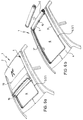
- FIGS. 6a and 6b Various possible opening positions of the folding roof 1 can be seen from FIGS. 6a and 6b. These opening positions can be implemented individually or in combination with one another, although of course these representations do not reflect all possible ways of opening.
- 6a for example, the front area of the roof opening 6 is exposed in that the sliding connection device 3 is partially open in this front area.
- the field formed between a cross bracing 19 and the front edge of the cover part 2 is folded back onto the part of the cover part 2 still attached and can be fixed and held in this position with corresponding additional devices.
- tab-eye connections or interlocking devices come into consideration.
- Velcro fasteners can be used for this.
- FIG. 6a in the area of the rear transverse edge of the roof opening 6 the flexible cover part 2 is partially opened, so that the folding roof 1 in FIG. 6a also has a ventilation position and the air from the vehicle interior due to suction in the area of the rear edge 31 of the folding roof 1 can emerge.
- Fig. 6b the folding roof 1 is shown in such a state in which the roof opening 6 is almost completely released, but is still held in the area of the rear transverse edge on the fixed roof part 4 and rolled up there.
- the cover part 2 can even be removed altogether, and it can be stowed in the vehicle, so that the vehicle occupants have a convertible-like feeling through the completely exposed roof opening 6 is conveyed.
- the folding roof 1 enables the largest possible area of the roof opening 6 to be exposed, but that certain intermediate positions are also possible with the cover part 2, so that the cover part 2 of the folding roof 1 can partially release the roof opening 6 in a variety of ways. If, for example, the removed cover part 2 is to be attached again to close the roof opening 6, it is placed over the roof opening 6 such that the edge stiffeners 16, 16 'and the tensioning cable 21 of the flexible cover part 2, as shown in FIGS.
- the assembly of the folding roof 1 will be briefly explained below. Installation on the vehicle assembly line serves as an example.
- the vehicle roof reaches the assembly station for the folding roof 1 in such a way that the upstanding boundary edge 7 of the roof opening 6 is already preformed.
- the profile part 5, 5 ' is then plugged onto this upstanding boundary edge 7 in the manner shown in FIG. 2.
- the flexible cover part 2 needs to be placed under positioning with the aid of the profile part 5, 5 ', and the sections 3', 3 '' of the sliding connection device 3 can then be closed with a smooth sliding movement of the slide or slides 15, and then the folding roof 1 is reliably and tightly connected to the fixed roof part 4 of the vehicle and with the tensioning device 34 a predetermined convertible top tension is applied.
- the flexible cover part 2 with the inserted cross stiffeners 19, the edge stiffeners 16, 16 'and the circumferential tensioning cable as a further stiffening part 21 is designed as a prefabricated supplier part.
- the folding roof 1 can be installed quickly and easily in the roof opening 6 of the vehicle. An inexpensive installation is thus achieved.
- the design can also be made, for example, in such a way that the cover part 2, without using a sliding connection device 3, for example on the rear Cross edge of the roof opening 6 can be fastened.
- interlocking devices can optionally be provided, which can be detached from each other after unlocking and unlocking so that the cover part 2 can be removed from the vehicle roof as a whole.
- the cover part 2 can also comprise, for example, only two folding fields in deviation from the embodiment shown.
- the design of the folding roof 1 can be made such that the cross stiffeners 19 have a curved profile in cross section.
Landscapes
- Engineering & Computer Science (AREA)
- Mechanical Engineering (AREA)
- Seal Device For Vehicle (AREA)
Applications Claiming Priority (2)
| Application Number | Priority Date | Filing Date | Title |
|---|---|---|---|
| DE19904040254 DE4040254C1 (fr) | 1990-12-17 | 1990-12-17 | |
| DE4040254 | 1990-12-17 |
Publications (2)
| Publication Number | Publication Date |
|---|---|
| EP0491148A1 true EP0491148A1 (fr) | 1992-06-24 |
| EP0491148B1 EP0491148B1 (fr) | 1994-09-07 |
Family
ID=6420510
Family Applications (1)
| Application Number | Title | Priority Date | Filing Date |
|---|---|---|---|
| EP19910118608 Expired - Lifetime EP0491148B1 (fr) | 1990-12-17 | 1991-10-31 | Toit ouvrant pliable pour véhicules |
Country Status (3)
| Country | Link |
|---|---|
| EP (1) | EP0491148B1 (fr) |
| JP (1) | JPH04271923A (fr) |
| DE (1) | DE4040254C1 (fr) |
Cited By (1)
| Publication number | Priority date | Publication date | Assignee | Title |
|---|---|---|---|---|
| FR3153040A1 (fr) | 2023-09-19 | 2025-03-21 | Psa Automobiles Sa | toit ouvrant à support de baleine de rigidification et véhiculé équipé du toit ouvrant. |
Families Citing this family (4)
| Publication number | Priority date | Publication date | Assignee | Title |
|---|---|---|---|---|
| DE4319718C1 (de) * | 1993-06-15 | 1994-08-18 | Webasto Karosseriesysteme | Faltdach für Fahrzeuge |
| DE19533898C2 (de) * | 1995-09-13 | 2001-07-12 | Anton Bauer | Dachrahmen |
| DE19616971A1 (de) * | 1996-04-27 | 1997-10-30 | Bayerische Motoren Werke Ag | Kraftfahrzeug mit einer Dachöffnung |
| DE102021209634A1 (de) | 2021-09-01 | 2023-03-02 | Volkswagen Aktiengesellschaft | Dachsystem für ein Kraftfahrzeug, Kraftfahrzeug |
Citations (4)
| Publication number | Priority date | Publication date | Assignee | Title |
|---|---|---|---|---|
| GB432141A (en) * | 1934-05-12 | 1935-07-22 | Vanden Plas England 1923 Ltd | Improvements in, or relating to, weather-protective fittings for motor-cars of the open-tourer type |
| GB945571A (en) * | 1961-09-20 | 1964-01-02 | Austin Motor Co Ltd | Improvements relating to motor vehicle roofs |
| US3476437A (en) * | 1965-08-11 | 1969-11-04 | Porsche Kg | Top for motor vehicles,especially for passenger motor vehicles |
| US4611849A (en) * | 1983-03-26 | 1986-09-16 | Dr.Ing. H.C.F. Porsche Ag | Convertible top with interchangeable flexible and rigid rear windows for a passenger motor vehicle |
Family Cites Families (3)
| Publication number | Priority date | Publication date | Assignee | Title |
|---|---|---|---|---|
| GB2076751A (en) * | 1980-05-21 | 1981-12-09 | Stevens Anthony Design Ltd | Fixing An Openable Roof or Roof Member to a Vehicle |
| DE8205999U1 (de) * | 1982-03-04 | 1982-07-08 | Dr.Ing.H.C. F. Porsche Ag, 7000 Stuttgart | Verdeckbezug fuer ein klappverdeck eines fahrzeuges, insbesondere eines personenwagens |
| DE8816696U1 (de) * | 1988-12-06 | 1990-05-03 | Mehler Vario System GmbH, 6400 Fulda | Lösbare Fensterbefestigung in einem flexiblen Klappverdeck eines Fahrzeuges |
-
1990
- 1990-12-17 DE DE19904040254 patent/DE4040254C1/de not_active Expired - Fee Related
-
1991
- 1991-10-31 EP EP19910118608 patent/EP0491148B1/fr not_active Expired - Lifetime
- 1991-11-01 JP JP28792891A patent/JPH04271923A/ja active Pending
Patent Citations (4)
| Publication number | Priority date | Publication date | Assignee | Title |
|---|---|---|---|---|
| GB432141A (en) * | 1934-05-12 | 1935-07-22 | Vanden Plas England 1923 Ltd | Improvements in, or relating to, weather-protective fittings for motor-cars of the open-tourer type |
| GB945571A (en) * | 1961-09-20 | 1964-01-02 | Austin Motor Co Ltd | Improvements relating to motor vehicle roofs |
| US3476437A (en) * | 1965-08-11 | 1969-11-04 | Porsche Kg | Top for motor vehicles,especially for passenger motor vehicles |
| US4611849A (en) * | 1983-03-26 | 1986-09-16 | Dr.Ing. H.C.F. Porsche Ag | Convertible top with interchangeable flexible and rigid rear windows for a passenger motor vehicle |
Cited By (1)
| Publication number | Priority date | Publication date | Assignee | Title |
|---|---|---|---|---|
| FR3153040A1 (fr) | 2023-09-19 | 2025-03-21 | Psa Automobiles Sa | toit ouvrant à support de baleine de rigidification et véhiculé équipé du toit ouvrant. |
Also Published As
| Publication number | Publication date |
|---|---|
| EP0491148B1 (fr) | 1994-09-07 |
| JPH04271923A (ja) | 1992-09-28 |
| DE4040254C1 (fr) | 1992-01-16 |
Similar Documents
| Publication | Publication Date | Title |
|---|---|---|
| DE4437773C1 (de) | Instrumententafel mit einem integrierten, aufklappbaren Gassackdeckel | |
| DE3929159C2 (de) | Dichtprofilleiste | |
| DE69731729T2 (de) | Flexible gleitschiene für glassscheiben mit angeformtem versteifungsteil | |
| DE10013531C1 (de) | Trenn- und Abdeckvorrichtung für Fahrzeuge, insbesondere für Kombinations-Personenkraftwagen od. dgl. | |
| DE10063770B4 (de) | Windschutzvorrichtung für ein Kraftfahrzeug | |
| DE102016009136B4 (de) | Kraftwagen mit einem Dachmodul | |
| EP0491158B1 (fr) | Toit pliant pour véhicule | |
| EP1633586B1 (fr) | Capote pour vehicule automobile | |
| EP1925482A2 (fr) | Capote pour un cabriolet | |
| EP0491148B1 (fr) | Toit ouvrant pliable pour véhicules | |
| DE10116593B4 (de) | Fahrzeugdach | |
| DE69905674T2 (de) | Dicht-, Zier- und Abdeckungsprofilleisten | |
| DE10104007C2 (de) | Fahrzeugsitz, insbesondere Sportwagensitz | |
| EP0610457B1 (fr) | Coupe-vent pour cabriolets | |
| EP1927493A2 (fr) | Arceau pour un véhicule cabriolet | |
| EP1059184A2 (fr) | Dispositif pour fixer le bord périphérique d'un revêtement intérieur d'un véhicule à un capote pliante | |
| EP2382104B1 (fr) | Pavillon de cabriolet avec au moins deux segments de toit et une garniture | |
| DE10056894B4 (de) | Cabriolet-Fahrzeug | |
| EP0805057B1 (fr) | Toit pliant pour véhicules comme cabriolets ou similaires | |
| EP0997334A2 (fr) | Véhicule automobile équipé d'un toit pliant | |
| DE8101640U1 (de) | Kraftfahrzeug mit einem festen dach, das wenigstens eine oeffnung und eine flexible abdeckung fuer diese oeffnung aufweist | |
| DE4314717C2 (de) | Fahrzeugdach mit einem zumindestens teilweise aus flexiblem Verdeckstoff bestehenden Verdeck | |
| DE102008058160A1 (de) | Kraftfahrzeug mit einem offenen Aufbau | |
| DE1630951A1 (de) | Verdeck fuer Fahrzeuge | |
| EP3388268A1 (fr) | Véhicule cabriolet doté d'un dispositif de maintien pour une capote rabattu |
Legal Events
| Date | Code | Title | Description |
|---|---|---|---|
| PUAI | Public reference made under article 153(3) epc to a published international application that has entered the european phase |
Free format text: ORIGINAL CODE: 0009012 |
|
| AK | Designated contracting states |
Kind code of ref document: A1 Designated state(s): ES FR GB IT NL |
|
| 17P | Request for examination filed |
Effective date: 19920707 |
|
| 17Q | First examination report despatched |
Effective date: 19931222 |
|
| GRAA | (expected) grant |
Free format text: ORIGINAL CODE: 0009210 |
|
| AK | Designated contracting states |
Kind code of ref document: B1 Designated state(s): ES FR GB IT NL |
|
| PG25 | Lapsed in a contracting state [announced via postgrant information from national office to epo] |
Ref country code: IT Free format text: LAPSE BECAUSE OF FAILURE TO SUBMIT A TRANSLATION OF THE DESCRIPTION OR TO PAY THE FEE WITHIN THE PRE;WARNING: LAPSES OF ITALIAN PATENTS WITH EFFECTIVE DATE BEFORE 2007 MAY HAVE OCCURRED AT ANY TIME BEFORE 2007. THE CORRECT EFFECTIVE DATE MAY BE DIFFERENT FROM THE ONE RECORDED.SCRIBED TIME-LIMIT Effective date: 19940907 Ref country code: NL Effective date: 19940907 Ref country code: GB Effective date: 19940907 Ref country code: ES Free format text: THE PATENT HAS BEEN ANNULLED BY A DECISION OF A NATIONAL AUTHORITY Effective date: 19940907 Ref country code: FR Effective date: 19940907 |
|
| EN | Fr: translation not filed | ||
| NLV1 | Nl: lapsed or annulled due to failure to fulfill the requirements of art. 29p and 29m of the patents act | ||
| GBV | Gb: ep patent (uk) treated as always having been void in accordance with gb section 77(7)/1977 [no translation filed] |
Effective date: 19940907 |
|
| PLBE | No opposition filed within time limit |
Free format text: ORIGINAL CODE: 0009261 |
|
| STAA | Information on the status of an ep patent application or granted ep patent |
Free format text: STATUS: NO OPPOSITION FILED WITHIN TIME LIMIT |
|
| 26N | No opposition filed |