EP0491303A2 - Dispositif pour arrêter l'avance dans un tour ou une fraiseuse conventionelle - Google Patents
Dispositif pour arrêter l'avance dans un tour ou une fraiseuse conventionelle Download PDFInfo
- Publication number
- EP0491303A2 EP0491303A2 EP91121437A EP91121437A EP0491303A2 EP 0491303 A2 EP0491303 A2 EP 0491303A2 EP 91121437 A EP91121437 A EP 91121437A EP 91121437 A EP91121437 A EP 91121437A EP 0491303 A2 EP0491303 A2 EP 0491303A2
- Authority
- EP
- European Patent Office
- Prior art keywords
- feed
- path
- drive motor
- speed
- tool slide
- Prior art date
- Legal status (The legal status is an assumption and is not a legal conclusion. Google has not performed a legal analysis and makes no representation as to the accuracy of the status listed.)
- Withdrawn
Links
Images


Classifications
-
- G—PHYSICS
- G05—CONTROLLING; REGULATING
- G05B—CONTROL OR REGULATING SYSTEMS IN GENERAL; FUNCTIONAL ELEMENTS OF SUCH SYSTEMS; MONITORING OR TESTING ARRANGEMENTS FOR SUCH SYSTEMS OR ELEMENTS
- G05B19/00—Program-control systems
- G05B19/02—Program-control systems electric
- G05B19/18—Numerical control [NC], i.e. automatically operating machines, in particular machine tools, e.g. in a manufacturing environment, so as to execute positioning, movement or co-ordinated operations by means of program data in numerical form
- G05B19/416—Numerical control [NC], i.e. automatically operating machines, in particular machine tools, e.g. in a manufacturing environment, so as to execute positioning, movement or co-ordinated operations by means of program data in numerical form characterised by control of velocity, acceleration or deceleration
-
- G—PHYSICS
- G05—CONTROLLING; REGULATING
- G05B—CONTROL OR REGULATING SYSTEMS IN GENERAL; FUNCTIONAL ELEMENTS OF SUCH SYSTEMS; MONITORING OR TESTING ARRANGEMENTS FOR SUCH SYSTEMS OR ELEMENTS
- G05B2219/00—Program-control systems
- G05B2219/30—Nc systems
- G05B2219/34—Director, elements to supervisory
- G05B2219/34387—Delay command as function of speed
-
- G—PHYSICS
- G05—CONTROLLING; REGULATING
- G05B—CONTROL OR REGULATING SYSTEMS IN GENERAL; FUNCTIONAL ELEMENTS OF SUCH SYSTEMS; MONITORING OR TESTING ARRANGEMENTS FOR SUCH SYSTEMS OR ELEMENTS
- G05B2219/00—Program-control systems
- G05B2219/30—Nc systems
- G05B2219/41—Servomotor, servo controller till figures
- G05B2219/41259—Coupling, clutch
-
- G—PHYSICS
- G05—CONTROLLING; REGULATING
- G05B—CONTROL OR REGULATING SYSTEMS IN GENERAL; FUNCTIONAL ELEMENTS OF SUCH SYSTEMS; MONITORING OR TESTING ARRANGEMENTS FOR SUCH SYSTEMS OR ELEMENTS
- G05B2219/00—Program-control systems
- G05B2219/30—Nc systems
- G05B2219/42—Servomotor, servo controller kind till VSS
- G05B2219/42308—Watchdog or integrator to detect no change or excess in feedback
-
- G—PHYSICS
- G05—CONTROLLING; REGULATING
- G05B—CONTROL OR REGULATING SYSTEMS IN GENERAL; FUNCTIONAL ELEMENTS OF SUCH SYSTEMS; MONITORING OR TESTING ARRANGEMENTS FOR SUCH SYSTEMS OR ELEMENTS
- G05B2219/00—Program-control systems
- G05B2219/30—Nc systems
- G05B2219/42—Servomotor, servo controller kind till VSS
- G05B2219/42318—Using two, more, redundant measurements or scales to detect bad function
-
- G—PHYSICS
- G05—CONTROLLING; REGULATING
- G05B—CONTROL OR REGULATING SYSTEMS IN GENERAL; FUNCTIONAL ELEMENTS OF SUCH SYSTEMS; MONITORING OR TESTING ARRANGEMENTS FOR SUCH SYSTEMS OR ELEMENTS
- G05B2219/00—Program-control systems
- G05B2219/30—Nc systems
- G05B2219/43—Speed, acceleration, deceleration control ADC
- G05B2219/43115—Adaptive stopping
-
- G—PHYSICS
- G05—CONTROLLING; REGULATING
- G05B—CONTROL OR REGULATING SYSTEMS IN GENERAL; FUNCTIONAL ELEMENTS OF SUCH SYSTEMS; MONITORING OR TESTING ARRANGEMENTS FOR SUCH SYSTEMS OR ELEMENTS
- G05B2219/00—Program-control systems
- G05B2219/30—Nc systems
- G05B2219/50—Machine tool, machine tool null till machine tool work handling
- G05B2219/50187—Stop drive motor if clutch refuses, remains active, if emergency
-
- G—PHYSICS
- G05—CONTROLLING; REGULATING
- G05B—CONTROL OR REGULATING SYSTEMS IN GENERAL; FUNCTIONAL ELEMENTS OF SUCH SYSTEMS; MONITORING OR TESTING ARRANGEMENTS FOR SUCH SYSTEMS OR ELEMENTS
- G05B2219/00—Program-control systems
- G05B2219/30—Nc systems
- G05B2219/50—Machine tool, machine tool null till machine tool work handling
- G05B2219/50188—If operation, feed movement not done after maximum allowable time, emergency stop
-
- G—PHYSICS
- G05—CONTROLLING; REGULATING
- G05B—CONTROL OR REGULATING SYSTEMS IN GENERAL; FUNCTIONAL ELEMENTS OF SUCH SYSTEMS; MONITORING OR TESTING ARRANGEMENTS FOR SUCH SYSTEMS OR ELEMENTS
- G05B2219/00—Program-control systems
- G05B2219/30—Nc systems
- G05B2219/50—Machine tool, machine tool null till machine tool work handling
- G05B2219/50198—Emergency stop
Definitions
- the invention relates to a device for switching off a feed in a conventional lathe or milling machine according to the preamble of claim 1 and a corresponding method.
- the operator uses these counters in such a way that they specify a certain distance and count down this distance down to "zero".
- the zero crossing therefore means "target dimension reached”.
- a tool part e.g. the chuck
- the invention has for its object to develop a device of the type mentioned in such a way that increased security is achieved in a simple manner.
- An essential idea of the invention is that no assessment to be entered by the operator has been made, Rather, a follow-up distance is determined as a function of the (actual) feed speed and the feed is switched off before the desired path thus modified is reached.
- a default converter is preferably provided, which links the overtravel to the feed rate via a proportionality factor.
- This proportionality factor is primarily machine-dependent and is saved in the default converter.
- the accuracy can be increased by setting the proportionality factor in several stages depending on the feed rate. This setting is made automatically to facilitate operation.
- the proportionality factor can either be entered by the operator in accordance with the selected feed rate, or determined during the current machining process from the measured feed rate (first derivation of the feed path according to time).
- test runs can be carried out and the resulting measured values can be saved.
- Such a "learning process” can also be carried out by the operator. It is possible to set the values either in a pure test run, i.e. without machining a workpiece at the same time.
- the machining process is stopped after the set feed speed has been reached (this can be seen from the fact that the feed speed no longer changes) (the feed is switched off), from which the proportionality factor is calculated between the switching off and the actual standstill of the feed and then the processing process is continued (if necessary the tool is moved back a short distance before the tool is started again at the selected feed speed in the selected feed direction).
- the processing process is continued (if necessary the tool is moved back a short distance before the tool is started again at the selected feed speed in the selected feed direction).
- An emergency shutdown device is preferably provided which is designed such that when the feed continues to operate for a defined period of time after the desired path has been reached, the main motor of the machine is shut down.
- Another system is involved in that the motor itself is switched off, not the mechanical connection between the drive motor and the spindle. This redundancy increases security, so that even in the event of a malfunction of the snail or the triggering associated organ, greater damage to the workpiece or damage to the machine can be avoided with increased security.
- the emergency shutdown can comprise a delay element which, when the actual path corresponds to the desired path, starts to run and switches off in the drive motor when a determined delay time has expired.
- a delay element which, when the actual path corresponds to the desired path, starts to run and switches off in the drive motor when a determined delay time has expired.
- the emergency shutdown device comprises a separate feed scanning device which is independent of the measuring device mentioned at the beginning detects movement of the tool carriage.
- the drive motor is switched off if, when the actual path has already corresponded to the target path, that is to say the final dimension has been reached, there is still a feed movement.
- a simple rotary encoder can be used for motion detection, which determines whether the spindle belonging to a feed is still rotating or not.
- the emergency shutdown device can comprise an emergency shutdown computer, which is connected to the feed scanning device and the input device and is designed in such a way that a maximum feed time period is calculated from the speed of movement of the tool slide and the entered desired path.
- the drive motor is switched off when the feed scanning device still detects a movement of the tool slide (or rotation of the tool spindle) after the maximum feed time has expired.
- This system is therefore practically completely independent of both the comparison device (actual value with setpoint) and the associated displacement measuring device.
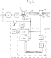
- a conventional lathe (or milling machine) usually comprises a drive motor 10, which is connected via a gear 11 and a coupling 9 to a spindle 15, which moves a tool slide 16 when it rotates.
- the clutch 9 comprises a pivotable fall screw 12, which is in the engaged position of the clutch 9 with a worm wheel 13 and is held in this position.
- a release element 14 is provided which enables the fall screw 12 to move away from the worm wheel 13, so that the clutch 9 is then disengaged.
- a scale 17 is attached to the guide bed (not shown) of the machine and can be scanned by means of an (optical or magnetic) sensor 18 which is mounted on the tool slide 16.
- the output signals of the sensor 18 are fed to a shutdown control 20.
- the shutdown control 20 comprises a counter 23 to which the output signals of the sensor 18 are fed.
- the counter 23 has an input which is connected to an input keyboard 26.
- a preset value which corresponds to the predetermined target path can be entered into the counter 23 via the input keyboard 26.
- the output signals of the sensor 18 are also fed to the input of a speed detector 21, the output signal of which corresponds in amplitude (or its digital value) to the speed of the carriage 16.
- the speed value is fed to a default converter 22, which uses the operations described below to calculate a default value from the speed value, which is dimensioned such that when the clutch 9 is at this default value is disengaged before reaching the target value, the movement of the carriage 16 is actually ended at this time.
- the default value from the default converter 22 is fed to an input of a comparator 24, the other input of which is fed to the current state of the counter 23. If the data at both inputs match, the comparator 24 outputs an output signal which is fed to the trigger element 24 and controls it in such a way that the falling screw 12 is disengaged from the worm wheel 13 so that the clutch 9 is disengaged.
- the counter reading from the counter 23 continues to be fed to a display unit 25.
- the function is such that at the beginning the operator brings the tool slide 16 into a starting position from which a desired path is to be covered.
- the target path is entered via the keyboard 26. Then the feed is started (by manually engaging clutch 9).
- the sensor 18 emits output signals (a defined number of pulses per distance unit), which reduce the content of the counter 23.
- the counter 23 thus counts down.
- the output pulses of the sensor 18 are further converted in the speed detector 21 into a speed-proportional signal, which in the embodiment described above, for. B. can be done via a frequency / voltage conversion.
- the default converter 22 From the speed-proportional signal, the default converter 22 forms a default value which corresponds to a distance traveled in the same unit as is used in the counter 23 for setting the wake-up route. This distance is therefore at an input of the comparator 24.
- the falling screw 12 is triggered by means of the trigger element 14 and the spindle 15 stops. Since this stopping process takes a certain amount of time due to the moving masses, the tool slide 16 runs beyond the preset value and comes to rest at the setpoint.
- a machine-dependent proportional value (parameter) is stored in the default converter 22, by which the actual speed of the tool slide 16 is multiplied.
- the proportional value associated with a machine can now be determined in the factory and permanently programmed into the default converter 22.
- the default converter 22 is supplied not only with the speed-proportional signal from the speed detector 21, but also with the path-proportional signal from the sensor 18 (broken connection in FIG. 1).
- the user himself can now determine the proportional value associated with a certain feed speed of the tool slide 16 in a test run, with the slide 16 being moved over a certain distance the speed of interest and then let it stop, measuring the distance that is still covered after the clutch 9 is released.
- the proportional value associated with the speed in question can then be calculated from this value.
- FIG. 2 differs from that of FIG. 1 in that an emergency shutdown system is provided.
- this comprises a delay element 28 which is triggered by the output signal of the comparator 24. After the delay time set in the delay element 28 has elapsed, the delay element 28 emits an output signal which opens a relay switch 27, via which the drive motor 10 is supplied with current. As a result, the drive motor 10 is switched off and the tool slide 16 always stops.
- the delay time present in the delay element 28 can be set remotely. This remote setting is carried out via a signal line (shown interrupted in FIG. 2), which leads from the speed detector 21 to the delay element 28. Accordingly, a shorter delay time is set at higher carriage speeds.
- FIG. 3 A further embodiment of the invention is shown below with reference to FIG. 3, which differs from the previously described embodiments with regard to the emergency shutdown system just mentioned differs.
- a rotary sensor 29 which reports a rotation of the spindle 15.
- the output signal of the rotary sensor 29 is fed to an emergency shutdown computer 30, which can emit an output signal for opening the relay 27.
- the rotary sensor 29 simultaneously begins to emit signals.
- the first output signal thus defines the point in time at which the movement of the carriage 16 began.
- the emergency shutdown calculation 30 calculates the maximum amount of time that may pass at the present rotational speed of the spindle 15 (measured via the rotary sensor 29) until the preset desired path is reached. After the calculated period of time has elapsed, the emergency shutdown computer 30 checks whether the rotary sensor 29 still indicates a rotation of the spindle 15 or whether the rotation of the spindle 15 decreases in speed. If the spindle 15 rotates further or not slower, the emergency shutdown computer 30 controls the relay 27 so that the main motor 10 is stopped. In this way, the emergency shutdown system is completely independent of the feed shutdown described in the introduction, which of course increases the safety of the system considerably.
- shutdown control 20 (including the delay element 28) can be represented by means of a microprocessor or computer, which in turn shows that the present invention relates not only to a device, but also to a corresponding method.
Landscapes
- Engineering & Computer Science (AREA)
- Human Computer Interaction (AREA)
- Manufacturing & Machinery (AREA)
- Physics & Mathematics (AREA)
- General Physics & Mathematics (AREA)
- Automation & Control Theory (AREA)
- Numerical Control (AREA)
- Automatic Control Of Machine Tools (AREA)
Applications Claiming Priority (2)
| Application Number | Priority Date | Filing Date | Title |
|---|---|---|---|
| DE19904040764 DE4040764A1 (de) | 1990-12-19 | 1990-12-19 | Einrichtung zum abschalten eines vorschubs bei einer konventionellen drehmaschine oder fraese |
| DE4040764 | 1990-12-19 |
Publications (2)
| Publication Number | Publication Date |
|---|---|
| EP0491303A2 true EP0491303A2 (fr) | 1992-06-24 |
| EP0491303A3 EP0491303A3 (en) | 1994-09-28 |
Family
ID=6420776
Family Applications (1)
| Application Number | Title | Priority Date | Filing Date |
|---|---|---|---|
| EP9191121437A Withdrawn EP0491303A3 (en) | 1990-12-19 | 1991-12-13 | Means to stop feed in a conventional turning or milling machine |
Country Status (2)
| Country | Link |
|---|---|
| EP (1) | EP0491303A3 (fr) |
| DE (1) | DE4040764A1 (fr) |
Cited By (2)
| Publication number | Priority date | Publication date | Assignee | Title |
|---|---|---|---|---|
| EP0809822A4 (fr) * | 1994-09-28 | 1997-12-03 | ||
| CN114450124A (zh) * | 2019-07-03 | 2022-05-06 | 赛科泰克两合股份有限公司 | 刀具夹 |
Families Citing this family (2)
| Publication number | Priority date | Publication date | Assignee | Title |
|---|---|---|---|---|
| DE10130183B4 (de) * | 2001-06-22 | 2005-03-10 | Brose Fahrzeugteile | Verfahren zur Positionserfassung eines elektro-motorisch angetriebenen Verstellsystem eines Kraftfahrzeugs |
| DE10338593B4 (de) * | 2003-03-21 | 2014-07-03 | Steuerungstechnik Bbh Gmbh | Verfahren sowie System zur Überwachung und/oder Steuerung des Nachlaufweges eines Fahrantriebs oder einer Verfahrachse |
Family Cites Families (7)
| Publication number | Priority date | Publication date | Assignee | Title |
|---|---|---|---|---|
| DE1061877B (de) * | 1954-12-13 | 1959-07-23 | Wohlenberg Kommanditgesellscha | Steuereinrichtung fuer Vorschubantriebe von Werkzeugmaschinen |
| DE1809052C3 (de) * | 1968-11-15 | 1974-05-22 | Ruesch Werke Dornbirn A.Ruesch & Co, Dornbirn (Oesterreich) | Vorrichtung zum Verhindern von Schrägschnitten bei Metallsägemaschinen |
| DE2740810A1 (de) * | 1977-09-10 | 1979-03-15 | Index Werke Kg Hahn & Tessky | Sicherheitsschaltvorrichtung fuer werkzeugmaschinen |
| CA1209498A (fr) * | 1982-04-22 | 1986-08-12 | Gordon M. Sommer | Mecanisme combine d'embrayage et de freinage a controle de fonctions |
| JPS5919654A (ja) * | 1982-07-22 | 1984-02-01 | Amada Co Ltd | Nc工作機械の非常時における電源遮断方法 |
| JP2572564B2 (ja) * | 1983-08-22 | 1997-01-16 | 株式会社 エスジー | 電気モータの位置決め制御装置 |
| DE3910888A1 (de) * | 1989-04-04 | 1990-10-11 | Mayr Christian Gmbh & Co Kg | Positionierantrieb |
-
1990
- 1990-12-19 DE DE19904040764 patent/DE4040764A1/de active Granted
-
1991
- 1991-12-13 EP EP9191121437A patent/EP0491303A3/de not_active Withdrawn
Cited By (2)
| Publication number | Priority date | Publication date | Assignee | Title |
|---|---|---|---|---|
| EP0809822A4 (fr) * | 1994-09-28 | 1997-12-03 | ||
| CN114450124A (zh) * | 2019-07-03 | 2022-05-06 | 赛科泰克两合股份有限公司 | 刀具夹 |
Also Published As
| Publication number | Publication date |
|---|---|
| EP0491303A3 (en) | 1994-09-28 |
| DE4040764C2 (fr) | 1993-09-16 |
| DE4040764A1 (de) | 1992-07-02 |
Similar Documents
| Publication | Publication Date | Title |
|---|---|---|
| DE19960834B4 (de) | Verfahren und Vorrichtung zur Störungserfassung, insbesondere zur Kollisionserfassung, im Antriebssystem einer numerisch gesteuerten Werkzeugmaschine | |
| DE2847510C2 (fr) | ||
| EP1987316B1 (fr) | Surveillance fiable de la vitesse d'appareils de mesure de coordonnees | |
| DE2827711C2 (de) | Einrichtung zur Überwachung der Betriebszeiten von Werkzeugen und von dem Verschleiß ausgesetzten Maschinenteilen in einer Maschine | |
| WO2001092777A1 (fr) | Dispositif de protection pour machines telles que presses-plieuses, decoupeuses, machines a estamper ou analogues | |
| WO2002020213A2 (fr) | Machine-outil | |
| DE2802994C2 (de) | Steuerungsvorrichtung für die Vorschubbewegungen an einer Schleifmaschine | |
| EP2431114A2 (fr) | Tour doté d'une broche de guidage et de traction et d'une commande électronique pour le coulisseau longitudinal et/ou transversal | |
| DE3618349C2 (fr) | ||
| DE3714028C2 (fr) | ||
| EP0491303A2 (fr) | Dispositif pour arrêter l'avance dans un tour ou une fraiseuse conventionelle | |
| DE2935723C2 (de) | Überwachungseinrichtung für die Vorschubbewegung eines programmgesteuert angetriebenen Maschinenteils | |
| DE2054643A1 (de) | Vorrichtung zur Bestimmung von Abmessungen | |
| EP3957423B1 (fr) | Architecture de sécurité pour machines d'usinage du bois | |
| DE2145323C3 (de) | Numerisch arbeitende Programmsteuerung für eine Gewindeschneidemaschine | |
| DE102016004569B4 (de) | Numerische Steuervorrichtung mit Koordinatenwerterfassungsfunktion, die weder ein Skip-Signal noch eine Tastenbetätigung benötigt | |
| DE68916917T2 (de) | Verfahren zur rückkehr zum ursprung. | |
| DE3837526C2 (fr) | ||
| DE2201445B2 (de) | Elektrische Steuerungsvorrichtung für die Hubbewegung von Werkzeug- oder Werkstückträgern an Werkzeugmaschinen, insbesondere Honmaschinen | |
| DE102020100208A1 (de) | Verpackungsmaschine und Verfahren zur Verstellung mehrerer Maschinenelemente an einer Verpackungsmaschine | |
| DE2425209C2 (de) | Verfahren zur Steuerung und Überwachung des Zustell- und Schleifvorgangs von Werkstücken | |
| DE1927044A1 (de) | Schleifmaschine | |
| EP0169556B1 (fr) | Dispositif pour la surveillance et la commande d'un outil d'usinage | |
| DE3124866A1 (de) | Verfahren und einrichtung zum numerisch gesteuerten schneiden eines ein- oder mehrgaengigen gewindes in wenigstens zwei gewindeschneiddurchgaengen | |
| DE1563746C (de) | Anordnung zur numerischen Steuerung von Maschinen |
Legal Events
| Date | Code | Title | Description |
|---|---|---|---|
| PUAI | Public reference made under article 153(3) epc to a published international application that has entered the european phase |
Free format text: ORIGINAL CODE: 0009012 |
|
| AK | Designated contracting states |
Kind code of ref document: A2 Designated state(s): AT BE CH DE FR GB IT LI LU NL |
|
| PUAL | Search report despatched |
Free format text: ORIGINAL CODE: 0009013 |
|
| RHK1 | Main classification (correction) |
Ipc: G05B 19/416 |
|
| AK | Designated contracting states |
Kind code of ref document: A3 Designated state(s): AT BE CH DE FR GB IT LI LU NL |
|
| 17P | Request for examination filed |
Effective date: 19950302 |
|
| 17Q | First examination report despatched |
Effective date: 19960118 |
|
| STAA | Information on the status of an ep patent application or granted ep patent |
Free format text: STATUS: THE APPLICATION IS DEEMED TO BE WITHDRAWN |
|
| 18D | Application deemed to be withdrawn |
Effective date: 19970903 |