EP0491476A2 - Méthode de pondération fréquentielle en vue de la minimisation de la dureté au choc d'un système de suspension - Google Patents
Méthode de pondération fréquentielle en vue de la minimisation de la dureté au choc d'un système de suspension Download PDFInfo
- Publication number
- EP0491476A2 EP0491476A2 EP91310860A EP91310860A EP0491476A2 EP 0491476 A2 EP0491476 A2 EP 0491476A2 EP 91310860 A EP91310860 A EP 91310860A EP 91310860 A EP91310860 A EP 91310860A EP 0491476 A2 EP0491476 A2 EP 0491476A2
- Authority
- EP
- European Patent Office
- Prior art keywords
- motion
- frequency
- frequency signal
- actuator
- wheel
- Prior art date
- Legal status (The legal status is an assumption and is not a legal conclusion. Google has not performed a legal analysis and makes no representation as to the accuracy of the status listed.)
- Withdrawn
Links
Images


Classifications
-
- B—PERFORMING OPERATIONS; TRANSPORTING
- B60—VEHICLES IN GENERAL
- B60G—VEHICLE SUSPENSION ARRANGEMENTS
- B60G13/00—Resilient suspensions characterised by arrangement, location or type of vibration dampers
-
- B—PERFORMING OPERATIONS; TRANSPORTING
- B60—VEHICLES IN GENERAL
- B60G—VEHICLE SUSPENSION ARRANGEMENTS
- B60G17/00—Resilient suspensions having means for adjusting the spring or vibration-damper characteristics, for regulating the distance between a supporting surface and a sprung part of vehicle or for locking suspension during use to meet varying vehicular or surface conditions, e.g. due to speed or load
- B60G17/015—Resilient suspensions having means for adjusting the spring or vibration-damper characteristics, for regulating the distance between a supporting surface and a sprung part of vehicle or for locking suspension during use to meet varying vehicular or surface conditions, e.g. due to speed or load the regulating means comprising electric or electronic elements
- B60G17/018—Resilient suspensions having means for adjusting the spring or vibration-damper characteristics, for regulating the distance between a supporting surface and a sprung part of vehicle or for locking suspension during use to meet varying vehicular or surface conditions, e.g. due to speed or load the regulating means comprising electric or electronic elements characterised by the use of a specific signal treatment or control method
-
- B—PERFORMING OPERATIONS; TRANSPORTING
- B60—VEHICLES IN GENERAL
- B60G—VEHICLE SUSPENSION ARRANGEMENTS
- B60G17/00—Resilient suspensions having means for adjusting the spring or vibration-damper characteristics, for regulating the distance between a supporting surface and a sprung part of vehicle or for locking suspension during use to meet varying vehicular or surface conditions, e.g. due to speed or load
- B60G17/015—Resilient suspensions having means for adjusting the spring or vibration-damper characteristics, for regulating the distance between a supporting surface and a sprung part of vehicle or for locking suspension during use to meet varying vehicular or surface conditions, e.g. due to speed or load the regulating means comprising electric or electronic elements
- B60G17/016—Resilient suspensions having means for adjusting the spring or vibration-damper characteristics, for regulating the distance between a supporting surface and a sprung part of vehicle or for locking suspension during use to meet varying vehicular or surface conditions, e.g. due to speed or load the regulating means comprising electric or electronic elements characterised by their responsiveness, when the vehicle is travelling, to specific motion, a specific condition, or driver input
- B60G17/0165—Resilient suspensions having means for adjusting the spring or vibration-damper characteristics, for regulating the distance between a supporting surface and a sprung part of vehicle or for locking suspension during use to meet varying vehicular or surface conditions, e.g. due to speed or load the regulating means comprising electric or electronic elements characterised by their responsiveness, when the vehicle is travelling, to specific motion, a specific condition, or driver input to an external condition, e.g. rough road surface, side wind
-
- B—PERFORMING OPERATIONS; TRANSPORTING
- B60—VEHICLES IN GENERAL
- B60G—VEHICLE SUSPENSION ARRANGEMENTS
- B60G17/00—Resilient suspensions having means for adjusting the spring or vibration-damper characteristics, for regulating the distance between a supporting surface and a sprung part of vehicle or for locking suspension during use to meet varying vehicular or surface conditions, e.g. due to speed or load
- B60G17/02—Spring characteristics, e.g. mechanical springs and mechanical adjusting means
- B60G17/027—Mechanical springs regulated by fluid means
- B60G17/0272—Mechanical springs regulated by fluid means the mechanical spring being a coil spring
-
- B—PERFORMING OPERATIONS; TRANSPORTING
- B60—VEHICLES IN GENERAL
- B60G—VEHICLE SUSPENSION ARRANGEMENTS
- B60G17/00—Resilient suspensions having means for adjusting the spring or vibration-damper characteristics, for regulating the distance between a supporting surface and a sprung part of vehicle or for locking suspension during use to meet varying vehicular or surface conditions, e.g. due to speed or load
- B60G17/06—Characteristics of dampers, e.g. mechanical dampers
- B60G17/08—Characteristics of fluid dampers
-
- B—PERFORMING OPERATIONS; TRANSPORTING
- B60—VEHICLES IN GENERAL
- B60G—VEHICLE SUSPENSION ARRANGEMENTS
- B60G2202/00—Indexing codes relating to the type of spring, damper or actuator
- B60G2202/30—Spring/Damper and/or actuator Units
- B60G2202/32—The spring being in series with the damper and/or actuator
- B60G2202/322—The spring being in series with the damper and/or actuator the damper being controllable
-
- B—PERFORMING OPERATIONS; TRANSPORTING
- B60—VEHICLES IN GENERAL
- B60G—VEHICLE SUSPENSION ARRANGEMENTS
- B60G2300/00—Indexing codes relating to the type of vehicle
- B60G2300/02—Trucks; Load vehicles
-
- B—PERFORMING OPERATIONS; TRANSPORTING
- B60—VEHICLES IN GENERAL
- B60G—VEHICLE SUSPENSION ARRANGEMENTS
- B60G2300/00—Indexing codes relating to the type of vehicle
- B60G2300/12—Cycles; Motorcycles
-
- B—PERFORMING OPERATIONS; TRANSPORTING
- B60—VEHICLES IN GENERAL
- B60G—VEHICLE SUSPENSION ARRANGEMENTS
- B60G2300/00—Indexing codes relating to the type of vehicle
- B60G2300/14—Buses
-
- B—PERFORMING OPERATIONS; TRANSPORTING
- B60—VEHICLES IN GENERAL
- B60G—VEHICLE SUSPENSION ARRANGEMENTS
- B60G2300/00—Indexing codes relating to the type of vehicle
- B60G2300/16—Aeroplanes
-
- B—PERFORMING OPERATIONS; TRANSPORTING
- B60—VEHICLES IN GENERAL
- B60G—VEHICLE SUSPENSION ARRANGEMENTS
- B60G2300/00—Indexing codes relating to the type of vehicle
- B60G2300/32—Track vehicles
-
- B—PERFORMING OPERATIONS; TRANSPORTING
- B60—VEHICLES IN GENERAL
- B60G—VEHICLE SUSPENSION ARRANGEMENTS
- B60G2400/00—Indexing codes relating to detected, measured or calculated conditions or factors
- B60G2400/10—Acceleration; Deceleration
-
- B—PERFORMING OPERATIONS; TRANSPORTING
- B60—VEHICLES IN GENERAL
- B60G—VEHICLE SUSPENSION ARRANGEMENTS
- B60G2400/00—Indexing codes relating to detected, measured or calculated conditions or factors
- B60G2400/60—Load
-
- B—PERFORMING OPERATIONS; TRANSPORTING
- B60—VEHICLES IN GENERAL
- B60G—VEHICLE SUSPENSION ARRANGEMENTS
- B60G2400/00—Indexing codes relating to detected, measured or calculated conditions or factors
- B60G2400/90—Other conditions or factors
- B60G2400/91—Frequency
-
- B—PERFORMING OPERATIONS; TRANSPORTING
- B60—VEHICLES IN GENERAL
- B60G—VEHICLE SUSPENSION ARRANGEMENTS
- B60G2500/00—Indexing codes relating to the regulated action or device
- B60G2500/10—Damping action or damper
-
- B—PERFORMING OPERATIONS; TRANSPORTING
- B60—VEHICLES IN GENERAL
- B60G—VEHICLE SUSPENSION ARRANGEMENTS
- B60G2500/00—Indexing codes relating to the regulated action or device
- B60G2500/20—Spring action or springs
-
- B—PERFORMING OPERATIONS; TRANSPORTING
- B60—VEHICLES IN GENERAL
- B60G—VEHICLE SUSPENSION ARRANGEMENTS
- B60G2600/00—Indexing codes relating to particular elements, systems or processes used on suspension systems or suspension control systems
- B60G2600/18—Automatic control means
- B60G2600/182—Active control means
-
- B—PERFORMING OPERATIONS; TRANSPORTING
- B60—VEHICLES IN GENERAL
- B60G—VEHICLE SUSPENSION ARRANGEMENTS
- B60G2600/00—Indexing codes relating to particular elements, systems or processes used on suspension systems or suspension control systems
- B60G2600/18—Automatic control means
- B60G2600/184—Semi-Active control means
-
- B—PERFORMING OPERATIONS; TRANSPORTING
- B60—VEHICLES IN GENERAL
- B60G—VEHICLE SUSPENSION ARRANGEMENTS
- B60G2600/00—Indexing codes relating to particular elements, systems or processes used on suspension systems or suspension control systems
- B60G2600/28—Temporary fluctuations
-
- B—PERFORMING OPERATIONS; TRANSPORTING
- B60—VEHICLES IN GENERAL
- B60G—VEHICLE SUSPENSION ARRANGEMENTS
- B60G2600/00—Indexing codes relating to particular elements, systems or processes used on suspension systems or suspension control systems
- B60G2600/60—Signal noise suppression; Electronic filtering means
- B60G2600/602—Signal noise suppression; Electronic filtering means high pass
-
- B—PERFORMING OPERATIONS; TRANSPORTING
- B60—VEHICLES IN GENERAL
- B60G—VEHICLE SUSPENSION ARRANGEMENTS
- B60G2600/00—Indexing codes relating to particular elements, systems or processes used on suspension systems or suspension control systems
- B60G2600/90—Indexing codes relating to particular elements, systems or processes used on suspension systems or suspension control systems other signal treatment means
-
- B—PERFORMING OPERATIONS; TRANSPORTING
- B60—VEHICLES IN GENERAL
- B60G—VEHICLE SUSPENSION ARRANGEMENTS
- B60G2800/00—Indexing codes relating to the type of movement or to the condition of the vehicle and to the end result to be achieved by the control action
- B60G2800/16—Running
- B60G2800/162—Reducing road induced vibrations
Definitions
- This invention relates generally to an active suspension system, and more specifically, to an apparatus and method for an active vehicle suspension system incorporating frequency shaping characteristics to reduce impact harshness.
- FIG. 1 For a particular active and passive suspension system.
- the horizontal axis of FIG. 1 represents the hub damping as an undimensioned relationship of the time the wheel takes to stop oscillating after it encounters a road irregularity. As can be seen, the higher the hub damping the better wheel control is available, and thus the better the handling of the vehicle. As the hub damping decreases, the wheel bounce increases and the control and handling of the vehicle becomes more difficult and possibly unsafe.
- the vertical axis represents the peak-to-peak body load as the amount of force being transmitted to the vehicle from the suspension system. An increase in body load translates to an increase in harshness upon impact of a road irregularity.
- Solid line A represents the relationship between body load and hub damping for a specific vehicle having an active suspension system.
- Dashed line B represents the relationship between hub damping and body load for a particular vehicle having a passive suspension system.
- a reduction in hub damping reduces the harshness of a particular road disturbance.
- the hub damping cannot be reduced enough in the active system to achieve comparable impact harshness to that of the passive system before getting into a region of unreasonable wheel bounce. Unreasonable wheel bounce being defined as a factor of driver discomfort and/or loss of vehicle control. Therefore, this method of reducing the hub damping has met with limited success.
- FIG. 2 Another method to attempt to reduce the impact harshness of an active suspension system is the use of soft isolator bushings, as shown in FIG. 2.
- two devices for inducing wheel damping are shown between a sprung mass 10 and an unsprung mass 12.
- the sprung mass could be the body of a particular vehicle and the unsprung mass could be one of the vehicles wheels.
- the two wheel damping devices are a variable control damper 16 and an active actuator 18.
- Damper 16 can either be incorporated into a passive or active system and actuator 18 is generally used in an active system.
- a spring 14 is generally used in both a passive or active system to further increase suspension control.
- Two soft isolator bushings shown generally at 20 have been incorporated in conjunction with both damper 16 and active actuator 18 between the sprung mass 10 and the unsprung mass 12.
- Soft isolator bushings 20 help reduce impact harshness due to smaller impacts, as well as high frequency (noise) transmission of road disturbances which would be too small to be damped by wheel damping devices 16 and 18.
- higher peak damping forces are required to maintain proper wheel damping in a suspension system incorporating soft isolator bushings 20.
- higher damping forces results in increased transmission of larger single road disturbances, which results in increased impact harshness.
- a soft isolator bushing requires substantial bushing travel to prevent the bushing from encountering the bushing travel limits at too low of a load.
- an isolator bushing creates a bushing induced phase lag in the damper due to the up and down movement of the damper shifted in time from the up and down movement of the rest of the suspension system.
- isolator bushings are required for both passive and active suspension systems to reduce noise disturbances to the vehicle chassis, and the performance characteristics which result from the isolator bushings for both systems are similar.
- the system includes a motion sensor which may be, but is not limited to, a hub accelerometer.
- the motion sensor senses the motion of an unsprung mass and transmits a frequency signal indicative of this motion to a microprocessor.
- the microprocessor includes an encoded frequency shaping algorithm which shapes the frequency signal from the sensor to a signal having modified phase and magnitude components.
- the shaped signal is sent to an active control component such as an active hydraulic strut or damper, to provide proper damping.
- the shaped signal instructs the active damping component to adjust the damping to a value which will minimize impact harshness.
- the individual wheels of a vehicle such as a car, truck, bus, tank, aircraft, or motorcycle can be individually controlled to provide higher degrees of stability and performance, and further, reduce the amount of impact harshness as a result of sharp road irregularities.
- induced phase lag due to the isolator bushings and other system dynamics is compensated for.
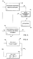
- FIG. 3 represents a schematic of a particular use of a preferred embodiment of the present invention.
- generally shown at 30 is an actively controlled suspension system of a vehicle.
- Reference numerals 32 represent the tires of the vehicle as unsprung masses.
- Reference numeral 34 represents the body of the vehicle as a sprung mass. The relationship between the unsprung mass and the sprung mass can be visualized in FIG. 2 as described above.
- Each unsprung mass 32 has a sensor 36 and an actuator 38.
- Sensor 36 can be a hub accelerometer for measuring the acceleration of the unsprung mass 32.
- Sensor 36 is not, however, limited to an accelerometer, and can be any other device which measures the motion of the hub, such as a velocity meter.
- Actuator 38 is an actively controlled actuator which provides a wide range of damping to the hub.
- Actuator 38 can be a hydraulic strut or a damper with an actively controlled orifice, but is not limited to these devices.
- Sensor 36 and actuator 38 can virtually be any appropriate component known in the art.
- System 30 further includes a microprocessor 40 or other applicable computing device.
- a microprocessor 40 or other applicable computing device.
- Incorporated within microprocessor 40 is a frequency response shaping network 42.
- Frequency response shaping network 42 has an input line 44 taken from each sensor 36.
- microprocessor 40 has an output line 46 connected to each actuator 38.
- Each unsprung mass 32 includes similar output lines 44 to the frequency response shaping network 42 and further each actuator 38 includes an input line 46 from the microprocessor.
- each actuator and sensor will be identical for each hub of the vehicle, however, different systems may require different sensors and actuators for desired results, and therefore different actuators and sensors may be used since each wheel may respond separately to certain road situations in relationship to the vehicle chassis.
- sensor 36 senses the motion of unsprung mass 32. This motion will generally be up and down for system 30.
- a frequency signal indicative of this motion is sent along lines 44 to frequency response shaping network 42.
- Frequency response shaping network 42 takes the frequency signal on line 44 and analyzes it in view of its components of phase and magnitude.
- Frequency response shaping network 42 then takes these individual components of phase and magnitude and shapes them by means of a predetermined algorithm stored in microprocessor 40.
- the shaped signal from frequency response shaping network 42 is applied to an output of microprocessor 40 along line 46 to apply the appropriate damping response to actuator 38. Therefore, actuator 38 applies the desired and appropriate damping to unsprung mass 32 in view of the movement of upsprung mass 32.
- the shaped damping response is applied to unsprung mass 32 such that the impact harshness due to a road irregularity which caused the sensor to react is minimized.
- Block 54 represents certain dynamics of individual parts of the vehicle which may be affected by a road irregularity. These dynamics include, but are not limited to, suspension, vehicle chassis and wheel dynamics.
- Line 52 represents an input to system 50, and is generally an input such as that which would be caused by a chuck hole or the like in the road.
- Line 56 represents an output line of the dynamics block 54. The output on line 56 would be an output from sensor 36 of FIG. 3, and would carry a frequency signal indicative of the response of the vehicle chassis, suspension and wheel relative to the magnitude of the signal on input line 52.
- Frequency response shaping block 58 takes the frequency signal on line 56 and analyzes it in view of its components of amplitude and phase as discussed above. These components are then applied to a predetermined algorithm to modify and shape the phase and magnitude of the frequency signal to a predetermined response frequency signal relative to the input components of phase and amplitude on line 56.
- This response is outputted on line 60 to a basic suspension control law block 64.
- Control law block 64 includes the control laws of the different dynamics of the vehicle. Also applied to control law block 64 as an input on line 62 is the dynamics information from block 54.
- Control law block 64 takes the dynamic response signals from block 54 and applies the modified frequency signal from block 58 to determine the appropriate damping of the hub to reduce impact harshness.
- the frequency response shaping network and basic suspension control laws would be stored in microprocessor 40.
- Microprocessor 40 computes the proper responses to the known characteristics from the control laws of the dynamics of the vehicle.
- the signal indicative of the appropriate damping is applied to an actuator represented by block 68 on line 66.
- the actuator as represented by block 68 then applies actuation to the dynamics of the vehicle of block 54 along line 70. By this, the motion of the wheel is controlled to minimize impact harshness depending on the impact represented on input line 52.
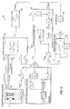
- FIG. 5 represents a specific implementation of an active suspension system 80 for a vehicle in which a hub accelerometer output is applied to a frequency response shaping network represented by acceleration filter 84 instead of the traditional gain amplification network for known active suspension systems.
- System 80 has a quarter car dynamics block 82 which includes the motion sensing and control of one wheel of a vehicle.
- Outputs of block 82 includes a load cell line F a which represents a force measurement on the suspension system, a hub accelerometer line which represents the acceleration of the up and down motion of the wheel, and an LVDT sensor line X a which represents the position of the wheel relative to the chassis.
- the output from the load cell F a , the acceleration filter 84 representing the frequency response shaping network ⁇ u , and position sensor X a are applied to a basic control law block 88 for providing the frequency shaped signal to the dynamics of the different components of the suspension system.
- the output ⁇ c of block 88 is applied to a high pass filter block 90 represented by a transfer function shown in block 90.
- the output ⁇ mod of high pass filter block 90 is applied to a bump stop 94 and then to a secondary filter 96 as shown.
- the combination of the position on line X a and the desired position determined by block 92, and the output from basic control law block 88 (after being filtered by the high pass and secondary filters) are applied to a summing junction 97, and applied via line 99 to an actuator compensation network represented by block 98.
- Block 98 determines the compensation of the actuator dynamics to improve its response to the commands.
- the output of actuator compensation block 98 is applied to the dynamics block 82 on line I c . Therefore the actuator is adjusted appropriately to apply the proper damping to the wheel to minimize the harshness.
- the frequency response shaping network incorporated as acceleration filter 84 for shaping the frequency output of the hub accelerometer provides one of the best means for shaping the frequency response to perform the desired damping.
- One method of filtering the frequency signal by the acceleration filter block 84 is shown in FIG. 6 in a dual block format type.
- the input on line 104 from the hub accelerometer is applied to the blocks 100 and 102 having the specific transfer functions as shown within the blocks.
- Kv is a constant
- S is the Laplace variable
- Z is the break frequency of the phase lead term
- p1 and p2 are the break frequencies of the phase lag terms
- ⁇ is the reciprocal of the break frequency of a phase lead term
- ⁇ is the natural frequency and ⁇ the damping ratio of a second order rolloff.
- These transfer functions would be stored in microprocessor 40.
- Other transfer functions for other desirable frequency shaping characteristics could be stored in microprocessor 40.
- the output of blocks 100 and 102 are combined to form an output 106 which is applied to the basic control law block
- line C represents the response curve between hub damping and body load of a suspension system according to a preferred embodiment of this invention incorporating an isolator bushing 20 having a stiffness which is relatively soft or has lower damping.
- the harshness of the system has been reduced from prior art active suspension systems as shown by line A.
- Incorporation of a stiffer isolator bushing (50% stiffer than line C) which is comparable to a passive suspension bushing, can realize performance characteristics as shown on line D.
- the impact harshness has been reduced to a degree which is even less than that of the passive system represented by line B.
Landscapes
- Engineering & Computer Science (AREA)
- Mechanical Engineering (AREA)
- Vehicle Body Suspensions (AREA)
Applications Claiming Priority (2)
| Application Number | Priority Date | Filing Date | Title |
|---|---|---|---|
| US07/628,046 US5218546A (en) | 1990-12-17 | 1990-12-17 | Frequency shaping method for minimizing impact harshness of suspension system |
| US628046 | 1990-12-17 |
Publications (2)
| Publication Number | Publication Date |
|---|---|
| EP0491476A2 true EP0491476A2 (fr) | 1992-06-24 |
| EP0491476A3 EP0491476A3 (en) | 1993-11-18 |
Family
ID=24517216
Family Applications (1)
| Application Number | Title | Priority Date | Filing Date |
|---|---|---|---|
| EP19910310860 Withdrawn EP0491476A3 (en) | 1990-12-17 | 1991-11-26 | Frequency shaping method for minimizing impact harshness of suspension system |
Country Status (5)
| Country | Link |
|---|---|
| US (1) | US5218546A (fr) |
| EP (1) | EP0491476A3 (fr) |
| JP (1) | JP2659032B2 (fr) |
| KR (1) | KR950013511B1 (fr) |
| MX (1) | MX9102577A (fr) |
Cited By (1)
| Publication number | Priority date | Publication date | Assignee | Title |
|---|---|---|---|---|
| FR2851742A1 (fr) * | 2003-02-28 | 2004-09-03 | Arslanian Pierre Jean Der | Suspension stabilisatrice pour l'asservissement d'attitude de vehicule roulants |
Families Citing this family (12)
| Publication number | Priority date | Publication date | Assignee | Title |
|---|---|---|---|---|
| DE4112005A1 (de) * | 1991-04-12 | 1992-10-15 | Bosch Gmbh Robert | System zur bildung eines signals bei einem fahrzeug |
| KR970011089B1 (ko) * | 1992-02-14 | 1997-07-07 | 미쯔비시 지도샤 고교 가부시끼가이샤 | 노면상태의 식별방법 및 써스펜션의 제어 장치 |
| US6259982B1 (en) * | 1993-02-02 | 2001-07-10 | Trw Inc. | Method and apparatus for controlling an active suspension system |
| DE19514844A1 (de) * | 1994-05-02 | 1995-11-09 | Fichtel & Sachs Ag | Anordnung zur Steuerung einer Fahrwerk-Einrichtung |
| JPH08300928A (ja) * | 1995-05-01 | 1996-11-19 | Toyota Motor Corp | 車両用サスペンション装置及び同装置のための電気制御装置 |
| US6026339A (en) * | 1997-06-12 | 2000-02-15 | Trw Inc. | Apparatus and method for providing an inertial velocity signal in an active suspension control system |
| US7512520B2 (en) * | 2003-08-19 | 2009-03-31 | Tramanco Pty Ltd. | Method for logging the performance of a vehicle suspension system |
| US7085636B2 (en) * | 2003-10-17 | 2006-08-01 | Visteon Global Technologies, Inc. | Transmissibility shaping control for active vehicle suspension systems |
| US20050206099A1 (en) * | 2004-03-17 | 2005-09-22 | Visteon Global Technologies, Inc. | Frequency domain ride control for low bandwidth active suspension systems |
| US8321177B2 (en) * | 2004-08-19 | 2012-11-27 | Tramanco Pty Ltd. | Method for logging the performance of a vehicle suspension system |
| US7751959B2 (en) * | 2005-06-21 | 2010-07-06 | Tenneco Automotive Operating Company Inc. | Semi-active suspension system with anti-roll for a vehicle |
| DE102015205369B4 (de) * | 2014-04-04 | 2019-08-22 | Ford Global Technologies, Llc | Verfahren zum Betrieb eines Federungssystems |
Family Cites Families (11)
| Publication number | Priority date | Publication date | Assignee | Title |
|---|---|---|---|---|
| USRE27623E (en) * | 1969-01-31 | 1973-04-17 | Millican suspension system for automobiles | |
| US4770438A (en) * | 1984-01-20 | 1988-09-13 | Nissan Motor Co., Ltd. | Automotive suspension control system with road-condition-dependent damping characteristics |
| JPS61163011A (ja) * | 1985-01-14 | 1986-07-23 | Nissan Motor Co Ltd | 電子制御ショックアブソ−バ装置 |
| DE3633159A1 (de) * | 1985-10-12 | 1987-04-16 | Volkswagen Ag | Verfahren und schaltungsanordnung zur adaptiven regelung und/oder steuerung von fahrwerksparametern eines strassenfahrzeugs |
| JPS63106122A (ja) * | 1986-10-24 | 1988-05-11 | Mazda Motor Corp | 車両のサスペンシヨン装置 |
| JPS6452911U (fr) * | 1987-09-30 | 1989-03-31 | ||
| US4984820A (en) * | 1988-07-22 | 1991-01-15 | Toyota Jidosha Kabushiki Kaisha | Damping force control system for shock absorber variable with frequency of vehicle height difference exceeding limit value |
| JPH0295918A (ja) * | 1988-09-30 | 1990-04-06 | Suzuki Motor Co Ltd | エア・サスペンション装置 |
| JP2565384B2 (ja) * | 1988-09-30 | 1996-12-18 | 富士重工業株式会社 | 自動車用アクティブサスペンションの制御装置 |
| JP2502372B2 (ja) * | 1989-04-28 | 1996-05-29 | 日産自動車株式会社 | 車両用流体圧供給装置 |
| US5097419A (en) * | 1990-06-08 | 1992-03-17 | Monroe Auto Equipment Company | Method and apparatus for dynamic leveling |
-
1990
- 1990-12-17 US US07/628,046 patent/US5218546A/en not_active Expired - Fee Related
-
1991
- 1991-11-26 EP EP19910310860 patent/EP0491476A3/en not_active Withdrawn
- 1991-12-16 KR KR1019910023100A patent/KR950013511B1/ko not_active Expired - Fee Related
- 1991-12-16 MX MX9102577A patent/MX9102577A/es not_active IP Right Cessation
- 1991-12-17 JP JP3352901A patent/JP2659032B2/ja not_active Expired - Lifetime
Cited By (1)
| Publication number | Priority date | Publication date | Assignee | Title |
|---|---|---|---|---|
| FR2851742A1 (fr) * | 2003-02-28 | 2004-09-03 | Arslanian Pierre Jean Der | Suspension stabilisatrice pour l'asservissement d'attitude de vehicule roulants |
Also Published As
| Publication number | Publication date |
|---|---|
| JPH04306115A (ja) | 1992-10-28 |
| KR920011788A (ko) | 1992-07-24 |
| MX9102577A (es) | 1992-06-01 |
| US5218546A (en) | 1993-06-08 |
| EP0491476A3 (en) | 1993-11-18 |
| KR950013511B1 (ko) | 1995-11-08 |
| JP2659032B2 (ja) | 1997-09-30 |
Similar Documents
| Publication | Publication Date | Title |
|---|---|---|
| US5390121A (en) | Banded on-off control method for semi-active dampers | |
| US9114683B2 (en) | Vehicle control device and method | |
| US5488562A (en) | System for generating signals for control or regulation of a chassis controllable or regulable in its sequences of movement | |
| US5765115A (en) | Pneumatic tilt stabilization suspension system | |
| US5218546A (en) | Frequency shaping method for minimizing impact harshness of suspension system | |
| JPH04504701A (ja) | 陸用車輌の懸架制御のための制御装置 | |
| US8855856B2 (en) | Vehicle roll control method using controllable friction force of MR dampers | |
| US6564129B2 (en) | Motor vehicle dynamic control | |
| EP1104357B1 (fr) | Suspensions de vehicule | |
| WO1997030858A2 (fr) | Suspension a force constante, suspension a force quasi-constante, et algorithmes de regulation associes | |
| US5265704A (en) | Apparatus for damping courses of motion | |
| US6285935B1 (en) | Device for controlling suspension shock absorbers of vehicles with skewed phantom substitute | |
| US20050240326A1 (en) | Model free semi-active vehicle suspension system | |
| CN111137096A (zh) | 用于可变阻尼力阻尼器的控制系统 | |
| EP0311114B1 (fr) | Système de suspension à réglage actif pour véhicule automobile à caractéristiques d'amortissement variables avec la vitesse du véhicule | |
| Williams | Electronically controlled automotive suspensions | |
| US5400245A (en) | Shock absorber having controlled damping force characteristics for use in a suspension system of a vehicle | |
| EP0518056B1 (fr) | Procédé pour le réglage auto-ajustable, dépendant de la fréquence d'un mécanisme de roulement | |
| JP5316279B2 (ja) | 車両振動抑制装置 | |
| Satoh et al. | An active suspension employing an electrohydraulic pressure control system | |
| JP4515240B2 (ja) | 車両用懸架装置の制御装置 | |
| DE4202091C2 (fr) | ||
| US20250128562A1 (en) | Vehicle control device and vehicle control system | |
| US5383124A (en) | Process for undercarriage regulation | |
| US20090030561A1 (en) | Vehicle handling bias control system |
Legal Events
| Date | Code | Title | Description |
|---|---|---|---|
| PUAI | Public reference made under article 153(3) epc to a published international application that has entered the european phase |
Free format text: ORIGINAL CODE: 0009012 |
|
| AK | Designated contracting states |
Kind code of ref document: A2 Designated state(s): CH DE FR GB IT LI |
|
| PUAL | Search report despatched |
Free format text: ORIGINAL CODE: 0009013 |
|
| AK | Designated contracting states |
Kind code of ref document: A3 Designated state(s): CH DE FR GB IT LI |
|
| 17P | Request for examination filed |
Effective date: 19940421 |
|
| 17Q | First examination report despatched |
Effective date: 19950518 |
|
| STAA | Information on the status of an ep patent application or granted ep patent |
Free format text: STATUS: THE APPLICATION IS DEEMED TO BE WITHDRAWN |
|
| 18D | Application deemed to be withdrawn |
Effective date: 19951129 |