EP0491648A1 - Hubschraubergelenkrotor mit einer verbesserten Blatt-Nabe-Verbindung - Google Patents
Hubschraubergelenkrotor mit einer verbesserten Blatt-Nabe-Verbindung Download PDFInfo
- Publication number
- EP0491648A1 EP0491648A1 EP91630110A EP91630110A EP0491648A1 EP 0491648 A1 EP0491648 A1 EP 0491648A1 EP 91630110 A EP91630110 A EP 91630110A EP 91630110 A EP91630110 A EP 91630110A EP 0491648 A1 EP0491648 A1 EP 0491648A1
- Authority
- EP
- European Patent Office
- Prior art keywords
- yoke
- hub
- blade
- composite
- pitch change
- Prior art date
- Legal status (The legal status is an assumption and is not a legal conclusion. Google has not performed a legal analysis and makes no representation as to the accuracy of the status listed.)
- Withdrawn
Links
Images


Classifications
-
- B—PERFORMING OPERATIONS; TRANSPORTING
- B64—AIRCRAFT; AVIATION; COSMONAUTICS
- B64C—AEROPLANES; HELICOPTERS
- B64C27/00—Rotorcraft; Rotors peculiar thereto
-
- B—PERFORMING OPERATIONS; TRANSPORTING
- B64—AIRCRAFT; AVIATION; COSMONAUTICS
- B64C—AEROPLANES; HELICOPTERS
- B64C27/00—Rotorcraft; Rotors peculiar thereto
- B64C27/32—Rotors
- B64C27/33—Rotors having flexing arms
-
- B—PERFORMING OPERATIONS; TRANSPORTING
- B64—AIRCRAFT; AVIATION; COSMONAUTICS
- B64C—AEROPLANES; HELICOPTERS
- B64C27/00—Rotorcraft; Rotors peculiar thereto
- B64C27/32—Rotors
- B64C27/35—Rotors having elastomeric joints
Definitions
- This invention relates to articulated helicopter rotors and more particularly to such a rotor in which the blade is connected to the hub through a unique blade-to-hub connection comprising a spherical elastomeric bearing connected to the hub and a composite yoke connected to the bearing in series, and which passes through a central opening in the bearing and consists of a continuous strap of high tensile strength fibers bonded together and connected to the hub and the blade in pin-wrap construction.
- helicopters are generally divided into broad categories, namely, articulated rotor, flex-rotor and rigid rotor.
- articulated rotor the helicopter blades are connected to the helicopter hub through a blade-to-hub connection so as to be supported from the helicopter rotor hub for rotation therewith, and so as to be moveable in pitch change (torsional), lead-lag (horizontal), and flapping (vertical) motion with respect to the hub, and to have the loads generated during the creations of these motions reacted from the helicopter blade through the blade-to-hub connection back to the hub.
- Centrifugal loads generated by the blades during rotation must similarly be reacted back to the hub.
- the blade is mounted and supported from the hub so as to be pivotable about fixed pitch change, lead-lag flapping axes.
- a flex-rotor is to be distinguished from an articulated rotor in that these motions and loads are established and accommodated by the flexibility of the parts involved.
- each blade was connected to the rotor through plain bearings, one of which was mounted for rotation about each of the lead-lag, pitch change and flapping axes.
- This construction was heavy, required lubrication, substantial maintenance and is expensive to manufacture and is not ballistically tolerant.
- Such a construction is shown in U.S. Patent No. 2,853,141 to Leoni.
- Our invention incorporates modern composite materials into the yoke or spindle of a helicopter rotor and uses them in combination with a spherical elastomeric bearing to produce an articulated helicopter rotor in which the blades are capable of lead-lag, flapping and pitch change motion about coincident axes, and wherein the connection between the blades and the hub is capable of accommodating these motions and reacting these loads, while simultaneously reacting the centrifugal load generated by the blades during rotor rotation.
- the spherical elastomeric bearing is connected to the hub and is shaped to be concentric about the intersection of the blade pitch change, flapping and lead-lag axes and serves to accommodate and react substantially all blade pitch change, lead-lag and flapping motions and loads.
- the composite yoke or spindle passes through a central aperture in the elastomeric bearing and is fabricated by bonding together in a plastic matrix a substantial number of high tensile strength fibers, such as fibers of fiberglass or graphite, which extend unidirectionally with respect to each other so as to form a continuous belt of composite material, which constitutes the yoke.
- the composite yoke is pin-wrap connected to the blade at two spaced stations and to the elastomeric bearing at one station, and serves to react and impart the centrifugal loads generated by the blade during rotation therethrough to and through the elastomeric bearing and then back to the hub.
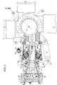
- Fig. 1 is a top view, partially broken away, of an articulated helicopter rotor showing our blade-to-hub connection.
- Fig. 2 is a view taken along line 2-2 of Fig. 1.
- Fig. 3 is a view taken along line 3-3 of Fig. 1.
- Fig. 4 is a view taken along line 4-4 of Fig. 1.
- Fig. 5 is a view taken along line 5-5 of Fig. 1.
- Fig. 6 is a view taken along line 6-6 of Fig. 1.
- Fig. 7 is a showing of an alternate arrangement of the elastomeric bearing which forms part of our blade-to-hub connection mechanism.
- articulated helicopter rotor 10 which comprises rotor hub 12 mounted for rotation about axis of rotation 14 and driven by a conventional engine and transmission system (not shown).
- a plurality of blades 16 extend radially from hub 12, and are each supported by blade-to-hub connector 18 to be movable in pitch change motion about pitch change axis 20, flapping motion about flapping axis 22 and lead-lag motion about lead-lag axis 23 (see Fig. 2) which is perpendicular to axes 20 and 22, and intersects axes 20 and 22 at point 24.
- Blade-to-hub connector 18 includes spherical elastomeric bearing 26 which has an outer race 28, an inner race 30, and a plurality of spherical laminates positioned concentrically about point 24 and positioned between the inner and outer races 28 and 30.
- the spherical laminates are alternate laminates of rigid material and elastomer bonded to the races 28 and 30, as well known in the art.
- Connector 18 also includes composite yoke or spindle 32 which is connected in series to elastomeric bearing 26 and which consists of a plurality of a unidirectional high tensile strength fibers, possibly of fiberglass or graphite, bonded together in a resin, possibly epoxy or other, matrix to form a continuous strap with one end thereof wrapped around connecting or anchor pin 34 in double thickness and extending therefrom in bifurcated fashion through central aperture 36 in the bearing inner race into two legs 38 and 40, with leg 38 wrapping around connecting pin 42, and leg 40 wrapping around connecting pin 44 in pin-wrap fashion. Rovings of fiber or cloth could be used with or instead of these fibers in forming yoke 32, depending upon the strength and flexibility desired for yoke 32.
- composite yoke 32 is of double thickness as it wraps around connecting pin 34, and is of single thickness as it wraps around connecting or anchor pins 42 and 44.
- the circular cross-section of the connecting pins is ideally suited to carry the various loads between the blades and the hub since all surfaces are of the open section type, that is, devoid of stress concentration factors and free of crack initiating areas.
- this composite yoke 32 is that visual maintenance inspection thereof is readily possible by merely visually detecting delamination of the composite material. Further, in view of the many high strength fibers which are bonded together to fabricate yoke 32, the yoke is ballistically tolerant in that the severing of certain of these fibers does not destroy the structural integrity of the yoke.
- yoke 32 forms into two legs 38a and 38b in passing around connecting pin 42 and similarly forms into two legs 40a and 40b in passing around connecting pin 44.
- An advantage of this construction is that the strength and stiffness of these legs can be controlled thru fabrication to suit the load carrying and stiffness requirements of yoke 32 in each rotor installation. Further, the legs 38a, 38b, 40a and 40b can be fabricated so that under the loss of any leg, the remaining structure can react full loads and accommodate all motions so as to make yoke 32 redundant, as well as ballistically tolerant.
- connecting pin 34 extends through aligned holes 46 and 48 in bearing inner race 30 and is locked in rigid position therein by conventional nut 50.
- connecting pin 42 passes through aligned apertures 52 and 54 of the root of blade 16, while connecting pin 44 is passing through similarly aligned holes in the root of blade 16.
- Connecting pin 42 is rigidly connected to the blade root and locked in that position by a conventional nut 56.
- Pin 44 is similarly connected to the blade root. It will be noted that connecting pins 42 and 44 are positioned substantially equal distances on opposite sides of the blade pitch change axis 20. This two pin spaced connection is necessary to react lead-lag loads of the blade since lag axis 23, is positioned radially inboard thereof.
- connecting pins 34, 42 and 44 which are preferably parallel to lead-lag axis 23, are enveloped by elongated or elliptically shaped anchor bushings 60, 62 and 64 which are positioned such that their longer axes extend substantially along pitch change axis 20 of blade 16.
- anchor bushings serve the function of minimizing stress concentrations in the connection between the composite strap and the elastomeric bearing inner race, simplifying installation and removal of the centering pins, providing a simplified locking mechanism for the centering pins, and may be removed and installed through access holes, (to be described hereinafter), in the hub arm.
- the anchor bushings 60-64 provide protection for the strap fibers and furnish greatly increased pin bending strength and a lower stress concentration in the wrapped fibers.
- the incorporation of elongated anchor bushings 60-64 reduces the stress concentration, resulting in improved bolt bending, to thereby allow a smaller than metal spindle diameter, and to also allow the use of a single spherical elastomeric bearing.
- a hub arm 66 envelopes each elastomeric bearing 26.
- the hub arm 66 is fabricated of a composite material so as to gain the advantages thereof including being light in weight, easy of manufacture, and ballistic tolerance.
- Arm 66 is circular in cross-section at its radially outboard end where it is connected by a series of circumferentially positioned bolts 68 to bearing outer race 28.
- Hub arm 66 is connected at its radially inner end to rotor hub 12 by a series of circumferentially positioned connecting bolts 70.
- Hub arm 66 preferably includes one or more access ports 72 which not only provide access to bearing 26 and connecting pin 34 for inspection and maintenance, but also serve to lighten hub arm 66 and provide cooling for bearing 26 and the other mechanisms which it envelops.
- Overwrap 74 which is made of laminates of composite material, possibly fiberglass, with adjacent cross ply laminates having high strength fibers therein extending substantially perpendicular to the fibers in adjacent laminates, envelops yoke 32 and is bonded thereto to provide pitch change (torsional), flapping (vertical) and lead-lag (horizontal) stiffness to yoke 38.
- Overwrap 74 permits see thru inspection and therefore does not prevent visual detection of delamination in the bonded fibers of yoke 32.
- yoke 32 be of small geometric configuration to permit use of the smallest possible elastomeric bearing 26 capable of performing the required load carrying and motion accommodating functions. Accordingly, and as best shown in Fig. 3, composite yoke 32 envelops connecting pin 34 and its anchor bushing 60 such that the legs 38a-40a are outboard of legs 38b-40b and that each is of rectangular cross section and coact to form a double strap wrapping around pin 34 and bushing 60 within overwrap 74. Now progressing radially outwardly along pitch change axis 20 along composite yoke 32 we see that at the station thereof shown in Fig.
- the legs 38a-40a and 38b-40b commence to curve about pitch change axis 20, and overwrap 74 changes shape in accommodation.
- Composite filler 76 is preferable glass fiber in a resin matrix and is positioned in between legs 38a-40a and 38b-40b. Additional composite filler 78 may be positioned between overwrap 74 and bearing inner race central aperture 36, if needed.
- legs 38a-40a and 38b-40b, in cooperation with overwrap 74 and filler 76, are of a circular cross section. This is the station at which yoke 32 passes inwardly of elastomeric bearing 26.
- This construction is important to our invention since this circular cross-sectional shape of yoke 32 of minimum dimension or diameter "d" at the Fig. 5 station in- board of elastomeric bearing 26 permits the use of the smallest elastomeric bearing 26 which is capable of accommodating all blade motions and reacting all blade loads encountered and generated in flapping, lead-lag and pitch change.
- yoke legs 38a, 38b, 40a and 40b have returned to rectangular shape in cross-section as they loop around connecting pins 42 and 44 and their associated anchor bushings 62 and 64.
- shaped composite filler 76 fills all voids between legs 38 and 40 throughout the radial dimension of yoke 32. As best shown in Fig. 1, composite filler 76 also fills the region between the bifurcated legs 38 and 40. Filler 76 serves to add additional rigidity and hence load carrying capability to yoke 32, in cooperation with overwrap 74, to better react pitch change, lead-lag and flapping loading, while retaining required flexibility.
- pitch change mechanism 80 includes members 82 and 84 which extend over and under composite yoke 32 and are connected by bolt mechanisms 86 to snugly engage yoke 32 at a radial station between the blade root and hub arm 66.
- Pitch change member 82 is connected to pitch change rod 88 through spherical joint 90.
- Pitch change rod 88 is operable in a vertical direction to cause pitch change mechanism 80 to cause yoke 32 and hence blade 16 to rotate about pitch change axis 20 to affect pitch change of the blade both cyclically or collectively with the other blades of the helicopter rotor.
- Member 82 of pitch change mechanism 80 also engages elastomeric lead-lag damper 92, to which it pivotally connects at pivot joint 94.
- the inner most shims 98 of elastomeric bearing could be made conical rather than spherical, so as to increase the shear load carrying capability of the elastomeric bearing.
- our improved articulated rotor includes a blade-to-hub connection 18 which comprises a spherical elastomeric bearing connected in series with a composite yoke, with the bearing connected to the hub, and the yoke pin-wrap connected to the bearing and to the blade at two spaced stations while passing through the central aperture of the elastomeric bearing.
- Our configuration results in a system which meets high aircraft standards of weight efficiency and ballistic tolerance, and is both redundant and visually inspectable, while providing suitable distribution of loads and strength characteristics.
- yoke 32 be made of composite material to achieve the advantages just described, an operable and efficient construction is achieved if yoke 32 were fabricated of metal using anchor pin retention.
Landscapes
- Engineering & Computer Science (AREA)
- Mechanical Engineering (AREA)
- Aviation & Aerospace Engineering (AREA)
- Sliding-Contact Bearings (AREA)
- Moulding By Coating Moulds (AREA)
- Compositions Of Macromolecular Compounds (AREA)
- Structures Of Non-Positive Displacement Pumps (AREA)
Applications Claiming Priority (2)
| Application Number | Priority Date | Filing Date | Title |
|---|---|---|---|
| US07/628,270 US5110260A (en) | 1990-12-17 | 1990-12-17 | Articulated helicopter rotor within an improved blade-to-hub connection |
| US628270 | 1990-12-17 |
Publications (1)
| Publication Number | Publication Date |
|---|---|
| EP0491648A1 true EP0491648A1 (de) | 1992-06-24 |
Family
ID=24518184
Family Applications (1)
| Application Number | Title | Priority Date | Filing Date |
|---|---|---|---|
| EP91630110A Withdrawn EP0491648A1 (de) | 1990-12-17 | 1991-12-12 | Hubschraubergelenkrotor mit einer verbesserten Blatt-Nabe-Verbindung |
Country Status (6)
| Country | Link |
|---|---|
| US (1) | US5110260A (de) |
| EP (1) | EP0491648A1 (de) |
| JP (1) | JPH04274996A (de) |
| KR (1) | KR920011864A (de) |
| AU (1) | AU639197B2 (de) |
| CA (1) | CA2056190A1 (de) |
Cited By (1)
| Publication number | Priority date | Publication date | Assignee | Title |
|---|---|---|---|---|
| GB2418709A (en) * | 2004-09-29 | 2006-04-05 | Rolls Royce Plc | Damped assembly |
Families Citing this family (21)
| Publication number | Priority date | Publication date | Assignee | Title |
|---|---|---|---|---|
| ITMI991127A1 (it) * | 1998-05-28 | 2000-11-21 | Eurocopter Deutschland | Pala per un rotore privo di supporto di un elicottero |
| DE10035334B4 (de) | 2000-07-20 | 2007-11-29 | Eurocopter Deutschland Gmbh | Flugzeugtür und eine Außenhaut einer Flugzeugtür |
| US7097169B2 (en) * | 2004-08-04 | 2006-08-29 | Skf Usa Inc. | Elastomeric bearing with modified cylindrical core |
| DE602004005989T2 (de) * | 2004-09-28 | 2007-12-20 | Agusta S.P.A. | Hubschrauberrotor mit einem Schwingungsdämpfer |
| DE06844162T8 (de) * | 2006-08-17 | 2011-11-17 | Bell Helicopter Textron Inc. | Drehflügelflugzeugdrehmomentkopplung mit segmentlagern |
| EP2154065B1 (de) * | 2008-08-14 | 2011-07-13 | Agusta S.p.A. | Hubschrauberrotor |
| EP2367719B1 (de) | 2008-12-11 | 2018-09-12 | Sikorsky Aircraft Corporation | Heckrotorblattbaugruppe mit bewegungsbegrenzer für ein elastomeres lagersystem |
| US8657581B2 (en) * | 2009-08-28 | 2014-02-25 | Gordon Holdings, Inc. | Thermoplastic rotor blade |
| US9169011B2 (en) | 2011-09-13 | 2015-10-27 | Sikorsky Aircraft Corporation | Rotor with blades including outer blade shell and inner structural member |
| US9308992B2 (en) | 2012-02-28 | 2016-04-12 | Sikorsky Aircraft Corporation | Helicopter blade retention composite yoke |
| US9322283B2 (en) | 2012-09-28 | 2016-04-26 | United Technologies Corporation | Airfoil with galvanic corrosion preventive shim |
| US9797257B2 (en) | 2012-12-10 | 2017-10-24 | General Electric Company | Attachment of composite article |
| US9777579B2 (en) | 2012-12-10 | 2017-10-03 | General Electric Company | Attachment of composite article |
| US10549841B2 (en) | 2014-05-30 | 2020-02-04 | Sikorsky Aircraft Corporation | Structurally efficient pin wrap |
| CN106697279B (zh) * | 2017-01-13 | 2023-12-26 | 重庆星环航空科技有限公司 | 一种小型无人直升机具有内置轴承的挥舞铰结构 |
| CN106741887B (zh) * | 2017-01-13 | 2023-12-26 | 重庆星环航空科技有限公司 | 外置挥舞铰减震套的多桨叶旋翼头结构 |
| US10597143B2 (en) * | 2017-08-22 | 2020-03-24 | Bell Helicopter Textron Inc. | Low moment rotor hub |
| US11111012B2 (en) * | 2019-10-01 | 2021-09-07 | Textron Innovations Inc. | Hub with integral elastomeric bearing |
| US11401040B2 (en) * | 2020-03-19 | 2022-08-02 | Textron Innovations Inc. | Rotor hub fairing with integral cooling capabilities |
| CN113942644B (zh) * | 2021-10-09 | 2023-04-28 | 中国直升机设计研究所 | 一种轴内操纵式旋翼操纵系统 |
| CN117104503B (zh) * | 2023-10-16 | 2025-09-09 | 成都联合飞机科技有限公司 | 一种无铰式变距桨毂、直升机旋翼及直升机 |
Citations (5)
| Publication number | Priority date | Publication date | Assignee | Title |
|---|---|---|---|---|
| US3759632A (en) * | 1972-07-05 | 1973-09-18 | United Aircraft Corp | Articulated helicopter rotor |
| FR2237802A1 (de) * | 1973-07-18 | 1975-02-14 | Lord Corp | |
| FR2465643A2 (fr) * | 1979-09-19 | 1981-03-27 | Messerschmitt Boelkow Blohm | Rotor pour appareil a voilure tournante |
| US4264277A (en) * | 1978-05-26 | 1981-04-28 | The Boeing Company | Redundant rotor blade retention system |
| US4306836A (en) * | 1978-05-25 | 1981-12-22 | Kaman Aerospace Corporation | Hub assembly |
Family Cites Families (15)
| Publication number | Priority date | Publication date | Assignee | Title |
|---|---|---|---|---|
| US2853141A (en) * | 1955-05-05 | 1958-09-23 | United Aircraft Corp | Rotor head |
| DE1531359B1 (de) * | 1967-07-11 | 1969-09-11 | Bolkow Gmbh | vierbattrotor fÜr drehflügelflugzeuge |
| US3475988A (en) * | 1968-02-08 | 1969-11-04 | Bendix Corp | End fitting for tie bar |
| US4012169A (en) * | 1973-05-10 | 1977-03-15 | Societe Nationale Industrielle Aerospatiale | Rotor for rotating wing type aircraft |
| DE2638148C3 (de) * | 1976-08-25 | 1980-09-18 | Messerschmitt-Boelkow-Blohm Gmbh, 8000 Muenchen | Rotor für ein Drehflügelflugzeug |
| US4108508A (en) * | 1977-02-01 | 1978-08-22 | Lord Corporation | Frustroconical laminated bearing |
| FR2397325A1 (fr) * | 1977-07-13 | 1979-02-09 | Aerospatiale | Moyeu de rotor, en particulier pour le rotor principal d'un helicoptere |
| US4227857A (en) * | 1977-08-19 | 1980-10-14 | Textron, Inc. | Composite flexural yoke for helicopters |
| US4242048A (en) * | 1977-09-30 | 1980-12-30 | The Boeing Company | Semi-articulated flexstrap |
| IT1129070B (it) * | 1980-04-03 | 1986-06-04 | Agusta Aeronaut Costr | Rotore a giunti elastomerici per elicotteri |
| US4419051A (en) * | 1982-02-16 | 1983-12-06 | The Boeing Company | Twin tension/torsion beam rotor system |
| US4568246A (en) * | 1983-03-22 | 1986-02-04 | United Technologies Corporation | Fiber reinforced/epoxy matrix composite helicopter rotor torque tube |
| US4585393A (en) * | 1983-03-22 | 1986-04-29 | United Technologies Corporation | Fiber reinforced/epoxy matrix composite helicopter rotor yoke |
| FR2616409B1 (fr) * | 1987-06-09 | 1989-09-15 | Aerospatiale | Pale en materiaux composites et son procede de fabrication |
| DE3807436C1 (de) * | 1988-03-07 | 1989-08-17 | Messerschmitt-Boelkow-Blohm Gmbh, 8012 Ottobrunn, De |
-
1990
- 1990-12-17 US US07/628,270 patent/US5110260A/en not_active Expired - Fee Related
-
1991
- 1991-11-26 CA CA002056190A patent/CA2056190A1/en not_active Abandoned
- 1991-12-12 JP JP3351645A patent/JPH04274996A/ja active Pending
- 1991-12-12 EP EP91630110A patent/EP0491648A1/de not_active Withdrawn
- 1991-12-16 KR KR1019910023102A patent/KR920011864A/ko not_active Withdrawn
- 1991-12-16 AU AU89788/91A patent/AU639197B2/en not_active Ceased
Patent Citations (5)
| Publication number | Priority date | Publication date | Assignee | Title |
|---|---|---|---|---|
| US3759632A (en) * | 1972-07-05 | 1973-09-18 | United Aircraft Corp | Articulated helicopter rotor |
| FR2237802A1 (de) * | 1973-07-18 | 1975-02-14 | Lord Corp | |
| US4306836A (en) * | 1978-05-25 | 1981-12-22 | Kaman Aerospace Corporation | Hub assembly |
| US4264277A (en) * | 1978-05-26 | 1981-04-28 | The Boeing Company | Redundant rotor blade retention system |
| FR2465643A2 (fr) * | 1979-09-19 | 1981-03-27 | Messerschmitt Boelkow Blohm | Rotor pour appareil a voilure tournante |
Cited By (2)
| Publication number | Priority date | Publication date | Assignee | Title |
|---|---|---|---|---|
| GB2418709A (en) * | 2004-09-29 | 2006-04-05 | Rolls Royce Plc | Damped assembly |
| GB2418709B (en) * | 2004-09-29 | 2007-10-10 | Rolls Royce Plc | Damped assembly |
Also Published As
| Publication number | Publication date |
|---|---|
| AU8978891A (en) | 1992-06-18 |
| US5110260A (en) | 1992-05-05 |
| CA2056190A1 (en) | 1992-06-18 |
| JPH04274996A (ja) | 1992-09-30 |
| AU639197B2 (en) | 1993-07-15 |
| KR920011864A (ko) | 1992-07-25 |
Similar Documents
| Publication | Publication Date | Title |
|---|---|---|
| US5110260A (en) | Articulated helicopter rotor within an improved blade-to-hub connection | |
| US5263821A (en) | Mid-beam jointed reconfigurable bearingless main rotor assembly | |
| CA1102774A (en) | Laminated composite rotor yoke | |
| EP0105419B1 (de) | Rotorsystem und Methode für Hubschrauber | |
| US5820344A (en) | Contoured flexure strap for helicopter rotor system | |
| EP0700350B1 (de) | Biegeplatte eines lagerlosen hauptrotoraggregats eines hubschraubers | |
| EP0888235B1 (de) | Faserverstärktes blattwurzelanschlussstück für hubschrauberrotoren | |
| CA1297312C (en) | Link-type rotary coupling | |
| EP1238906B1 (de) | Mehrblattheckrotornabe zur Entlastung des Coriolis-Effektes | |
| US5096380A (en) | Composite flexbeam for a bearingless helicopter rotor | |
| CA2036598A1 (en) | Flexbeam helicopter rotor with improved snubber-vibration damper between the torque tube and the flexible spar member | |
| EP2634091B1 (de) | Joch aus Faserverbundwerkstoff für eine Hubschrauberrotorblattbefestigung | |
| US5562416A (en) | Helicopter rotor blade mounting assembly | |
| US4247255A (en) | Composite rotor blade root end | |
| US4797064A (en) | Composite helicopter rotor hub | |
| EP0785889B1 (de) | Dämpfer lager haltevorrichtung für einen lagerfreien hubschrauberrotor | |
| US4349317A (en) | Bearingless rotor for single and tandem helicopters | |
| US6827553B2 (en) | Flexbeam damper assembly having transition shim clamp device | |
| US11541995B2 (en) | Rotor blade assembly for bearingless rotor |
Legal Events
| Date | Code | Title | Description |
|---|---|---|---|
| PUAI | Public reference made under article 153(3) epc to a published international application that has entered the european phase |
Free format text: ORIGINAL CODE: 0009012 |
|
| AK | Designated contracting states |
Kind code of ref document: A1 Designated state(s): DE FR GB IT |
|
| 17P | Request for examination filed |
Effective date: 19921215 |
|
| 17Q | First examination report despatched |
Effective date: 19940413 |
|
| 18D | Application deemed to be withdrawn |
Effective date: 19950927 |