EP0491950A1 - Procede de production de pieces constitutives de la tete d'impression d'une imprimante par points du type a impact - Google Patents
Procede de production de pieces constitutives de la tete d'impression d'une imprimante par points du type a impact Download PDFInfo
- Publication number
- EP0491950A1 EP0491950A1 EP91902764A EP91902764A EP0491950A1 EP 0491950 A1 EP0491950 A1 EP 0491950A1 EP 91902764 A EP91902764 A EP 91902764A EP 91902764 A EP91902764 A EP 91902764A EP 0491950 A1 EP0491950 A1 EP 0491950A1
- Authority
- EP
- European Patent Office
- Prior art keywords
- molding
- component
- binder
- members
- impact type
- Prior art date
- Legal status (The legal status is an assumption and is not a legal conclusion. Google has not performed a legal analysis and makes no representation as to the accuracy of the status listed.)
- Granted
Links
Images



Classifications
-
- B—PERFORMING OPERATIONS; TRANSPORTING
- B22—CASTING; POWDER METALLURGY
- B22F—WORKING METALLIC POWDER; MANUFACTURE OF ARTICLES FROM METALLIC POWDER; MAKING METALLIC POWDER; APPARATUS OR DEVICES SPECIALLY ADAPTED FOR METALLIC POWDER
- B22F3/00—Manufacture of workpieces or articles from metallic powder characterised by the manner of compacting or sintering; Apparatus specially adapted therefor ; Presses and furnaces
- B22F3/22—Manufacture of workpieces or articles from metallic powder characterised by the manner of compacting or sintering; Apparatus specially adapted therefor ; Presses and furnaces for producing castings from a slip
- B22F3/225—Manufacture of workpieces or articles from metallic powder characterised by the manner of compacting or sintering; Apparatus specially adapted therefor ; Presses and furnaces for producing castings from a slip by injection molding
-
- B—PERFORMING OPERATIONS; TRANSPORTING
- B41—PRINTING; LINING MACHINES; TYPEWRITERS; STAMPS
- B41J—TYPEWRITERS; SELECTIVE PRINTING MECHANISMS, i.e. MECHANISMS PRINTING OTHERWISE THAN FROM A FORME; CORRECTION OF TYPOGRAPHICAL ERRORS
- B41J2/00—Typewriters or selective printing mechanisms characterised by the printing or marking process for which they are designed
- B41J2/22—Typewriters or selective printing mechanisms characterised by the printing or marking process for which they are designed characterised by selective application of impact or pressure on a printing material or impression-transfer material
- B41J2/23—Typewriters or selective printing mechanisms characterised by the printing or marking process for which they are designed characterised by selective application of impact or pressure on a printing material or impression-transfer material using print wires
- B41J2/235—Print head assemblies
-
- B—PERFORMING OPERATIONS; TRANSPORTING
- B22—CASTING; POWDER METALLURGY
- B22F—WORKING METALLIC POWDER; MANUFACTURE OF ARTICLES FROM METALLIC POWDER; MAKING METALLIC POWDER; APPARATUS OR DEVICES SPECIALLY ADAPTED FOR METALLIC POWDER
- B22F7/00—Manufacture of composite layers, workpieces, or articles, comprising metallic powder, by sintering the powder, with or without compacting wherein at least one part is obtained by sintering or compression
- B22F7/06—Manufacture of composite layers, workpieces, or articles, comprising metallic powder, by sintering the powder, with or without compacting wherein at least one part is obtained by sintering or compression of composite workpieces or articles from parts, e.g. to form tipped tools
- B22F7/062—Manufacture of composite layers, workpieces, or articles, comprising metallic powder, by sintering the powder, with or without compacting wherein at least one part is obtained by sintering or compression of composite workpieces or articles from parts, e.g. to form tipped tools involving the connection or repairing of preformed parts
-
- B—PERFORMING OPERATIONS; TRANSPORTING
- B22—CASTING; POWDER METALLURGY
- B22F—WORKING METALLIC POWDER; MANUFACTURE OF ARTICLES FROM METALLIC POWDER; MAKING METALLIC POWDER; APPARATUS OR DEVICES SPECIALLY ADAPTED FOR METALLIC POWDER
- B22F2998/00—Supplementary information concerning processes or compositions relating to powder metallurgy
Definitions
- the present invention relates to a component which constitutes a printing heed for a wire impact type dot printer and a molding method thereof.
- a printing bead for a wire impact type dot printer is, as illustrated in FIG. 8, typically composed of: a nose frame a; a core block b fixed to a rear face thereof; a spring holder c provided in a central circular hole of the core block b; a yoke d mounted on the core block b; a multiplicity of printing levers 1 positioned and held on the yoke d; and a presser plate f which covers the printing levers.
- the core block b for constituting a magnetic circuit is constructed by joining a multiplicity of sub-cores b2 each formed of a material such as Permendur having a large saturated magnetic flux density in a soft iron base frame b1.
- the printing lever 1 is constructed by joining a lever 12 and a fulcrum pin 13 to a plunger 11 formed of Permendur. It requires a considerable number of steps to integrally joining these components. Besides, particularly in the core block b, a slight gap is invariably formed between the base frame and the core irrespective of the way of joining these members. This causes a magnetic loss. A backlash tends to be produced between the lever 12 and the fulcrum pin 13 of the printing lever 1. There arise inconveniences in which wire motions become unstable, and adverse influences are exerted on the respondency.
- a wire impact type dot head component characterized in that at least one member of a component configured as a joint body of a plurality of members is molded by use of metallic powder and then sintered, and this one member is integrally joined to another member in the above-described process.
- a method of molding such a head component comprising the steps of molding at least one member constituting the component by use of metallic powder by an injection molding method, sintering this one member and effecting integral sintering by joining this one member to another previously molded member in the above-described process.
- At least one member among the plurality of members constituting the magnetic circuit component for a printing head is molded by use of the metallic powder by injection molding and subsequently sintered.
- the foregoing member is joined to another member previously molded, thus effecting integral sintering.
- the plurality of members can be joined integrally and easily without a particular working accuracy of the joint portion. It is possible to remarkably reduce the number of assembling steps and the number of parts as well. An inter-member gap is eliminated, whereby the magnetic circuit component with almost no magnetic loss can be constructed. Further, it is possible to mold the component in which an expensive material exhibiting a high permeability is applied to only the parts required. Thus, the printing head can be constructed at still lower costs.
- Formation of one base frame 2 involves the steps of adding 5 - 60% by volume of an organic binder to powder of magnetic substance, having a particle diameter of 3 - 25u m, of pure iron Fe or 3% silicon steel Fe- Si and kneading these substances. Under an injection pressure of 300 - 3000 kgf/cm 2 by an injection molding machine, the kneaded substances are molded into a base frame prototype formed with a central circular hole 3 and a multiplicity of core fitting holes 4... which encompass the hole 3 in an inner bottom face. Pin gates are employed as those required for the injection molding, resulting in a reduction in the remainder of gates.
- the base frame 2 formed by the injection molding is joined simply by the binder.
- the base frame 2 exhibits a high workability and is therefore capable of easily removing the gate remainder.
- the runner is pulverized and kneaded, whereby it is reusable for injection molding.
- the base frame 2 can be therefore inexpensive.
- de-binder processing is effected in an inert gas or in vacuum for 2 - 60 hrs at 300 ° C - 700 ° C after being held for 1 - 3 hrs at, e.g., 50°C - 200 C.
- the binder composed of an organic substance is removed from the base frame 2.
- the other core 5 is formed in the following manner. Kneaded with the binder in the same manner with as the above-mentioned is powder of Permendur (Fe-Co- V alloy) having a large saturated magnetic flux density or 3% silicon steel Fe-Si having a large permeability or a nickel alloy Fe-Ni. The kneaded substances are injection-molded into a core prototype provided with fitting protrusions 6 on its lower face. Then, it undergoes de-binder processing.
- Permendur Fe-Co- V alloy
- the fitting protrusions 6 of the core prototype are fitted in the fitting holes 4 of the base frame prototype, thereby joining the two prototypes.
- the base frame fitting hole 4 is formed in a substantially rectangular parallelopiped shape.
- the configuration of the core fitting protrusion 6 is substantially the same as the substantially rectangular parallelopiped. Positions of the base frame 2 and the core 5 are thereby easily determined. Besides, a stepped portion 6a of the core protrusion 6 impinges on a bottom part 4a of the base frame, thereby easily determining the position.
- a method which uses a jig illustrated in FIG. 7 is also available.
- a jig 17 is formed with a groove 17a assuming a configuration corresponding to the core 5.
- the core 5 is inserted in this groove 17a.
- a depth of the groove 17a is so set that the stepped portion 6a of the protrusion 6 of the core 5 is higher than an upper face 17b of the jig.
- the core 5 is set in the jig 17.
- the fitting protrusion 6 of the core 5 is formed in, e.g., a substantially cylindrical shape, and the hole 4 of the base frame 2 assumes a configuration corresponding to the protrusion 6.
- the protrusions 6 are press-fitted in the holes 4, whereby the two members are joined.
- the joined body is sintered in Vacuum or in an atmosphere of inert gas.
- Molding is performed in this manner, interfaces between the base frame 2 and the cores 5 are welded.
- the base frame 2 and the cores 5 are integrally joined without any gap.
- a core block 1 with almost no magnetic loss is thereby obtained.
- the core block molded based on the method of the present invention exhibits a less magnetic loss and a higher energy efficiency than in the prior art.
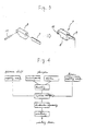
- FIGS. 3 and 4 show a method of molding a printing lever 7.
- a lever piece 9 is previously molded by press working from a plate material of pure iron Fe or 3% silicon steel Fe-Si or stainless steel each having a high strength.
- a fulcrum pin 10 is also previously molded by cutting work from a wire rod composed of carbon steel and the like.
- These members are molded integrally with a prototype of a plunger 8 by an insert method in the process of injection-molding the plunger prototype with a molding die while kneading an organic binder with powder of a high saturated magnetic flux density alloy or a high permeability alloy such as Permendur Fe-Co-V and the like. Subsequently, these members undergo de-binder processing and sintered in vacuum or in an atmosphere of inert gas.
- the binder is kneaded with powder of the high saturated magnetic flux density alloy or the high permeability alloy such as Permendur Fe-Co-V and the like.
- the plunger 8 is formed by injection molding. After effecting de-binder processing, the printing lever piece 9 is joined to the fulcrum pin 10. These members are sintered in vacuum or in the atmosphere of inert gas.
- Molding is performed in the manner discussed above, and it is possible to obtain the printing lever 7 showing a high energy efficiency, using an expensive material with a high permeability for the plunger 8 alone. Besides, the lever piece 9 and the fulcrum pin 10 are accurately firmly made integral with a predetermined portion of the plunger 8. Thus, the operation thereof can be stabilized.
- FIGS. 5 and 6 there is shown a method of molding a yoke 11.
- a disk-like yoke 12 are formed with a multiplicity of radial grooves 13... and fulcrum pin insertion recesses 14.
- a dish-like yoke 15 is formed with a multiplicity of radial grooves 16...
- the yokes 12 and 15 are molded by injection molding from a raw material obtained by kneading the binder with powder of pure iron Fe, or silicon steel Fe-Si or Permendur (Fe-Co-V alloy) as a magnetic material. Those yokes are subjected to de-binder processing. Subsequently, the prototypes of the yokes 12, 15 are superposed to align the radial grooves 13, 16 with each other and sintered in vacuum or in the atmosphere of inert gas.
- Molding is carried out in this manner, whereby the two yokes which could not be formed integrally so far can be integrally molded into a single yoke 11.
- Left in the portion where the binder existed in this yoke are minute voids smaller than fine powder particles. It is because sintering is effected after injection-molding the fine powder with the binder. It is feasible to configure the yoke 11 capable of permitting the printing lever 7 to smoothly surely operate as a porous yoke exhibiting a less magnetic loss and self-lubricity because of a lubricating oil impregnating in those voids.
- the present invention has been described by exemplifying the component applied to a typical suction type wire impact dot head.
- the present invention is, however, applicable to yokes used for store energy type dot heads using permanent magnets.
- a permanent magnet is formed beforehand of a material such as samarium cobalt or neodymium.
- the yokes are previously molded by sintering or press working by use of a material such as pure iron Fe or silicon steel Fe-Si.
- These members are made integral with the base frame by an outsert method in the process of injection-molding the base frame prototype by kneading the binder with powder of a ferromagnetic substance such as silicon steel Fe-Si or Permendur Fe-Co-V. After undergoing de-binder processing, those members are sintered.
- the yokes for constituting the magnetic circuit can be molded to reduce the magnetic loss to the greatest possible degree.
- the present invention is employed for the impact dot head of a dot printer and is applicable to all kinds of dot impact printers which will be spread from now onwards.
- the present invention largely contributes to an improvement of performance and a cost-down thereof.
Landscapes
- Engineering & Computer Science (AREA)
- Manufacturing & Machinery (AREA)
- Mechanical Engineering (AREA)
- Chemical & Material Sciences (AREA)
- Composite Materials (AREA)
- Materials Engineering (AREA)
- Powder Metallurgy (AREA)
- Impact Printers (AREA)
Abstract
Applications Claiming Priority (3)
| Application Number | Priority Date | Filing Date | Title |
|---|---|---|---|
| JP18678890A JPH03130306A (ja) | 1989-07-13 | 1990-07-12 | ワイヤインパクト式ドットプリンタ用印字ヘッドの構成部品とその成形方法 |
| JP186788/90 | 1990-07-12 | ||
| PCT/JP1991/000038 WO1992000850A1 (fr) | 1990-07-12 | 1991-01-17 | Pieces constitutives de la tete d'impression d'une imprimante par points du type a impact, et procede de production |
Publications (3)
| Publication Number | Publication Date |
|---|---|
| EP0491950A1 true EP0491950A1 (fr) | 1992-07-01 |
| EP0491950A4 EP0491950A4 (en) | 1993-09-29 |
| EP0491950B1 EP0491950B1 (fr) | 1997-03-26 |
Family
ID=16194603
Family Applications (1)
| Application Number | Title | Priority Date | Filing Date |
|---|---|---|---|
| EP91902764A Expired - Lifetime EP0491950B1 (fr) | 1990-07-12 | 1991-01-17 | Procede de production de pieces constitutives de la tete d'impression d'une imprimante par points du type a impact |
Country Status (7)
| Country | Link |
|---|---|
| US (1) | US5401107A (fr) |
| EP (1) | EP0491950B1 (fr) |
| KR (1) | KR100189304B1 (fr) |
| DE (1) | DE69125355T2 (fr) |
| HK (1) | HK1005021A1 (fr) |
| SG (1) | SG48222A1 (fr) |
| WO (1) | WO1992000850A1 (fr) |
Cited By (2)
| Publication number | Priority date | Publication date | Assignee | Title |
|---|---|---|---|---|
| EP0538073A3 (en) * | 1991-10-18 | 1993-12-15 | Fujitsu Ltd | Process for producing sintered body and magnet base |
| EP1563931A1 (fr) * | 2004-02-12 | 2005-08-17 | Basf Aktiengesellschaft | Procédé d'assemblage des pièces inorganiques produites par moulage par injection avec des pièces produites par un autre procédé |
Families Citing this family (1)
| Publication number | Priority date | Publication date | Assignee | Title |
|---|---|---|---|---|
| US5641920A (en) * | 1995-09-07 | 1997-06-24 | Thermat Precision Technology, Inc. | Powder and binder systems for use in powder molding |
Family Cites Families (16)
| Publication number | Priority date | Publication date | Assignee | Title |
|---|---|---|---|---|
| US3672482A (en) * | 1970-08-31 | 1972-06-27 | Ibm | Wire matrix print head |
| US4230038A (en) * | 1977-06-23 | 1980-10-28 | Helmut Falk | Matrix print head assembly |
| US4230412A (en) * | 1978-03-17 | 1980-10-28 | Helmut Falk | Matrix print head assembly |
| JPS56131906A (en) * | 1980-03-19 | 1981-10-15 | Nec Corp | Actuator |
| US4425299A (en) * | 1980-09-24 | 1984-01-10 | Sumitomo Electric Industries, Ltd. | Method for bonding sintered metal pieces |
| US4661002A (en) * | 1983-08-19 | 1987-04-28 | Canon Kabushiki Kaisha | Dot matrix printer |
| JPS6072747A (ja) * | 1983-09-29 | 1985-04-24 | Toshiba Corp | 印字ヘツド |
| US4652157A (en) * | 1983-12-21 | 1987-03-24 | Kabushiki Kaisha Toshiba | Printing wire |
| US4722824A (en) * | 1986-06-04 | 1988-02-02 | Fine Particle Technology Corp. | Method of joining green bodies prior to sintering |
| US4833980A (en) * | 1987-08-31 | 1989-05-30 | Mannesmann Tally Corporation | High efficiency coil posts for print hammer actuators |
| JPS6465099A (en) * | 1987-09-07 | 1989-03-10 | Hitachi Cable | Production of gaas single crystal |
| JPH01299054A (ja) * | 1988-05-27 | 1989-12-01 | Tokyo Electric Co Ltd | 釈放型ドツトプリンタヘツド |
| JP2588272B2 (ja) * | 1988-05-30 | 1997-03-05 | 川崎製鉄株式会社 | Fe−Co系焼結磁性材料の製造方法 |
| DE3917277C2 (de) * | 1989-05-24 | 1994-01-20 | Mannesmann Ag | Verfahren und Vorrichtung zur Herstellung von Fertigteilen als Verbundkörper aus pulverförmigen Werkstoffen |
| DE69024582T2 (de) * | 1989-10-06 | 1996-05-15 | Sumitomo Metal Mining Co | Stahllegierung zum Anwenden in spritzgegossenen pulvermetallurgisch hergestellten gesinterten Formkörpern |
| JPH0672747A (ja) * | 1992-08-24 | 1994-03-15 | Denki Kagaku Kogyo Kk | 注入用セメント混和材及びそれを用いた注入材 |
-
1991
- 1991-01-17 HK HK98104186A patent/HK1005021A1/en not_active IP Right Cessation
- 1991-01-17 KR KR1019920700549A patent/KR100189304B1/ko not_active Expired - Fee Related
- 1991-01-17 EP EP91902764A patent/EP0491950B1/fr not_active Expired - Lifetime
- 1991-01-17 SG SG1996008065A patent/SG48222A1/en unknown
- 1991-01-17 WO PCT/JP1991/000038 patent/WO1992000850A1/fr not_active Ceased
- 1991-01-17 DE DE69125355T patent/DE69125355T2/de not_active Expired - Fee Related
-
1994
- 1994-03-04 US US08/206,920 patent/US5401107A/en not_active Expired - Lifetime
Non-Patent Citations (2)
| Title |
|---|
| FUJITSU-SCIENTIFIC AND TECHNICAL JOURNAL vol. 24, no. 3, September 1988, KAWASAKI JP pages 254 - 261 , XP66411 W. YAMAGASHI AND T. LIKAWA 'Fe-50%Co Sintered Alloy for Magnetic Circuit Yoke' * |
| See also references of WO9200850A1 * |
Cited By (4)
| Publication number | Priority date | Publication date | Assignee | Title |
|---|---|---|---|---|
| EP0538073A3 (en) * | 1991-10-18 | 1993-12-15 | Fujitsu Ltd | Process for producing sintered body and magnet base |
| US5393484A (en) * | 1991-10-18 | 1995-02-28 | Fujitsu Limited | Process for producing sintered body and magnet base |
| US5487773A (en) * | 1991-10-18 | 1996-01-30 | Fujitsu Limited | Process for producing sintered body and magnet base |
| EP1563931A1 (fr) * | 2004-02-12 | 2005-08-17 | Basf Aktiengesellschaft | Procédé d'assemblage des pièces inorganiques produites par moulage par injection avec des pièces produites par un autre procédé |
Also Published As
| Publication number | Publication date |
|---|---|
| WO1992000850A1 (fr) | 1992-01-23 |
| KR920702292A (ko) | 1992-09-03 |
| DE69125355D1 (de) | 1997-04-30 |
| KR100189304B1 (ko) | 1999-06-01 |
| HK1005021A1 (en) | 1998-12-18 |
| EP0491950B1 (fr) | 1997-03-26 |
| US5401107A (en) | 1995-03-28 |
| DE69125355T2 (de) | 1997-07-03 |
| SG48222A1 (en) | 1998-04-17 |
| EP0491950A4 (en) | 1993-09-29 |
Similar Documents
| Publication | Publication Date | Title |
|---|---|---|
| US5487773A (en) | Process for producing sintered body and magnet base | |
| KR940011924B1 (ko) | 복수의 부재로 구성된 정밀부품의 동심상 결합방법 및 이것을 이용한 연료분사기의 노즐 조립방법 | |
| US5950932A (en) | Fuel injection valve | |
| US5687468A (en) | Process for manufacturing a magnetic circuit for a valve | |
| EP0301866A2 (fr) | Procédé de fabrication d'un moyeu magnétique | |
| JPH01102827A (ja) | 電磁リレーの接点ばね装置の製造方法 | |
| US5401107A (en) | Component of printing head for wire-impact type dot printer and molding method thereof | |
| JP2000280497A (ja) | アーマチュア及びその製造方法、ドットプリントヘッド | |
| HK1005021B (en) | Method of producing component parts of print head for wire impact type dot printer | |
| EP1238399A1 (fr) | Procede de production et de mise en magasin de composants magnetiques individuels, procede de montage de ces composants pour la realisation de systemes magnetiques miniaturises, et systemes magnetiques realises selon ce procede | |
| JPH02111556A (ja) | ワイヤニードル印刷ヘッド | |
| CN107517432B (zh) | 一种马达的制造方法及马达组件 | |
| CN116436185A (zh) | 三极磁体阵列 | |
| JPH03130306A (ja) | ワイヤインパクト式ドットプリンタ用印字ヘッドの構成部品とその成形方法 | |
| JPS61228603A (ja) | リフテイングマグネツト並びにその製法 | |
| JP2002524826A (ja) | 自動車のスタータ接触子 | |
| JP2005311248A (ja) | 磁路構成焼結部材及びその製造方法 | |
| JPS63110605A (ja) | 磁石の製造方法および装置 | |
| JP4707443B2 (ja) | 電磁ソレノイドおよびその部品ならびに製造方法 | |
| KR101647754B1 (ko) | 소형 스피커용 요크의 제조방법 및 이에 의해 제조된 소형 스피커용 요크 | |
| US4709175A (en) | Linear pulse motor | |
| JPS589313A (ja) | 複数の磁性体個片を含む一体化部品の製造方法 | |
| US11722039B2 (en) | Bi-material integrated polepiece | |
| CN107820194B (zh) | 一种动铁单元的制备方法及带料动铁 | |
| JP2007142221A (ja) | ステータコアおよびその製造方法 |
Legal Events
| Date | Code | Title | Description |
|---|---|---|---|
| PUAI | Public reference made under article 153(3) epc to a published international application that has entered the european phase |
Free format text: ORIGINAL CODE: 0009012 |
|
| AK | Designated contracting states |
Kind code of ref document: A1 Designated state(s): DE FR GB |
|
| 17P | Request for examination filed |
Effective date: 19920702 |
|
| A4 | Supplementary search report drawn up and despatched |
Effective date: 19930811 |
|
| AK | Designated contracting states |
Kind code of ref document: A4 Designated state(s): DE FR GB |
|
| 17Q | First examination report despatched |
Effective date: 19941228 |
|
| GRAG | Despatch of communication of intention to grant |
Free format text: ORIGINAL CODE: EPIDOS AGRA |
|
| GRAH | Despatch of communication of intention to grant a patent |
Free format text: ORIGINAL CODE: EPIDOS IGRA |
|
| GRAH | Despatch of communication of intention to grant a patent |
Free format text: ORIGINAL CODE: EPIDOS IGRA |
|
| GRAA | (expected) grant |
Free format text: ORIGINAL CODE: 0009210 |
|
| AK | Designated contracting states |
Kind code of ref document: B1 Designated state(s): DE FR GB |
|
| REF | Corresponds to: |
Ref document number: 69125355 Country of ref document: DE Date of ref document: 19970430 |
|
| ET | Fr: translation filed | ||
| PLBE | No opposition filed within time limit |
Free format text: ORIGINAL CODE: 0009261 |
|
| STAA | Information on the status of an ep patent application or granted ep patent |
Free format text: STATUS: NO OPPOSITION FILED WITHIN TIME LIMIT |
|
| 26N | No opposition filed | ||
| REG | Reference to a national code |
Ref country code: GB Ref legal event code: IF02 |
|
| PGFP | Annual fee paid to national office [announced via postgrant information from national office to epo] |
Ref country code: DE Payment date: 20070111 Year of fee payment: 17 |
|
| PGFP | Annual fee paid to national office [announced via postgrant information from national office to epo] |
Ref country code: GB Payment date: 20070117 Year of fee payment: 17 |
|
| PGFP | Annual fee paid to national office [announced via postgrant information from national office to epo] |
Ref country code: FR Payment date: 20070109 Year of fee payment: 17 |
|
| GBPC | Gb: european patent ceased through non-payment of renewal fee |
Effective date: 20080117 |
|
| PG25 | Lapsed in a contracting state [announced via postgrant information from national office to epo] |
Ref country code: DE Free format text: LAPSE BECAUSE OF NON-PAYMENT OF DUE FEES Effective date: 20080801 |
|
| REG | Reference to a national code |
Ref country code: FR Ref legal event code: ST Effective date: 20081029 |
|
| PG25 | Lapsed in a contracting state [announced via postgrant information from national office to epo] |
Ref country code: GB Free format text: LAPSE BECAUSE OF NON-PAYMENT OF DUE FEES Effective date: 20080117 |
|
| PG25 | Lapsed in a contracting state [announced via postgrant information from national office to epo] |
Ref country code: FR Free format text: LAPSE BECAUSE OF NON-PAYMENT OF DUE FEES Effective date: 20080131 |