EP0491988A1 - Dispositif de dosage pour fluide - Google Patents
Dispositif de dosage pour fluide Download PDFInfo
- Publication number
- EP0491988A1 EP0491988A1 EP90125555A EP90125555A EP0491988A1 EP 0491988 A1 EP0491988 A1 EP 0491988A1 EP 90125555 A EP90125555 A EP 90125555A EP 90125555 A EP90125555 A EP 90125555A EP 0491988 A1 EP0491988 A1 EP 0491988A1
- Authority
- EP
- European Patent Office
- Prior art keywords
- plunger
- cavity
- working chamber
- hollow nut
- input channel
- Prior art date
- Legal status (The legal status is an assumption and is not a legal conclusion. Google has not performed a legal analysis and makes no representation as to the accuracy of the status listed.)
- Withdrawn
Links
- 239000012530 fluid Substances 0.000 title claims abstract description 10
- 239000013013 elastic material Substances 0.000 claims abstract description 4
- 230000007704 transition Effects 0.000 claims abstract description 4
- 239000010687 lubricating oil Substances 0.000 abstract description 6
- 239000003921 oil Substances 0.000 description 11
- 238000010276 construction Methods 0.000 description 4
- 230000008859 change Effects 0.000 description 2
- 230000006835 compression Effects 0.000 description 2
- 238000007906 compression Methods 0.000 description 2
- 239000000463 material Substances 0.000 description 2
- 230000003252 repetitive effect Effects 0.000 description 2
- 230000009471 action Effects 0.000 description 1
- 230000003749 cleanliness Effects 0.000 description 1
- 230000001050 lubricating effect Effects 0.000 description 1
- 230000000149 penetrating effect Effects 0.000 description 1
- 230000002035 prolonged effect Effects 0.000 description 1
Images
Classifications
-
- G—PHYSICS
- G01—MEASURING; TESTING
- G01F—MEASURING VOLUME, VOLUME FLOW, MASS FLOW OR LIQUID LEVEL; METERING BY VOLUME
- G01F11/00—Apparatus requiring external operation adapted at each repeated and identical operation to measure and separate a predetermined volume of fluid or fluent solid material from a supply or container, without regard to weight, and to deliver it
- G01F11/02—Apparatus requiring external operation adapted at each repeated and identical operation to measure and separate a predetermined volume of fluid or fluent solid material from a supply or container, without regard to weight, and to deliver it with measuring chambers which expand or contract during measurement
- G01F11/04—Apparatus requiring external operation adapted at each repeated and identical operation to measure and separate a predetermined volume of fluid or fluent solid material from a supply or container, without regard to weight, and to deliver it with measuring chambers which expand or contract during measurement of the free-piston type
-
- F—MECHANICAL ENGINEERING; LIGHTING; HEATING; WEAPONS; BLASTING
- F16—ENGINEERING ELEMENTS AND UNITS; GENERAL MEASURES FOR PRODUCING AND MAINTAINING EFFECTIVE FUNCTIONING OF MACHINES OR INSTALLATIONS; THERMAL INSULATION IN GENERAL
- F16N—LUBRICATING
- F16N27/00—Proportioning devices
Definitions
- the invention relates to a metering device for fluid, in particular for metering lubricating oils, and is suitable for lubricating machine tools.
- a metering device of this type which consists of a body in which the input channel and the working chamber connected to it are located centrally.
- the working chamber is closed by a hollow nut with a central, step-like passage opening. It is located in the working chamber and in the opening of the hollow nut a plunger that is so specific that its base has a larger diameter than the other part located in the opening of the hollow nut.
- the passage between the base and the other part of the plunger is conical.
- the connection between the body and The hollow nut is thread-like and is compressed with a compression ring.
- the plunger is supported by a spring from the side of the hollow nut.
- a ball check valve is provided in the hollow nut.
- a disadvantage of this metering device is that it does not ensure an exact, exact metering of the fluid, and this within large limits depending on the voltage level, the number of metering devices installed in the system, the viscosity, the temperature and the cleanliness of the lubricating oils etc With different amounts of the dosing portion, the dimensions of the body, the plunger and the other components change in the construction, which hinders the unification of the corresponding elements.
- the object of the invention is to provide a dosing device for fluid, which ensures the exact and repetitive dosing of the fluid portions, regardless of the parameter changes of the system in which it is installed, and has a simple and technological construction and unification of the elements from the it exists.
- a metering device which consists of a body in which the inlet channel and working chamber are formed centrally, which in turn is closed by a hollow nut with a central step-shaped passage opening.
- a spring base is loosely mounted in the working chamber the working chamber to the input channel a conical surface.
- Such a conical surface also has the surface of the plunger lying there.
- This plunger is made of an elastic material and a cavity open on one side is formed in it from the side of the inlet channel.
- the inner end of the plunger is worked out with a shaped step in which a counter washer is mounted for the plunger.
- a conventional ball return valve is installed in the hollow nut.
- a second cavity is formed in the inner end of the plunger which is open on one side to the hollow nut which has a mandrel (protruding element) which is located in the second cavity.
- the outer surface of the mandrel which is located in the immediate vicinity of the hollow nut thread is conical and in its end it is cylindrical.
- the diameter of the second cavity is smaller than the largest diameter of the conical part of the dome.
- the advantages of the metering device are primarily determined by the specific construction of the plunger and by the material from which it is made. In this way, the constriction is simplified and technological.
- the elasticity of the material from which the plunger is made guarantees a constant dose of the supplied oil, with prolonged use. A maximum unification of the elements forming the dosing device is possible.
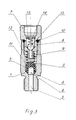
- the metering device consists of body 1, in which inlet channel 2 and working chamber 3 are formed lying axially.
- the transition between the input channel 2 and the working chamber 3 is a conical surface 4.
- a plunger 5 is loosely mounted, which is made of elastic material.
- a cavity 6, which is open on one side, is formed and the surface from this side of the plunger 5 is identical to the conical surface 4.
- the working chamber 3 of the metering device is closed by a hollow nut 7 mounted on an external thread 8.
- the hollow nut has a central step-shaped through opening 9 and is compressed to the body 1 by the compression ring 10.
- the plunger 5 is formed from the side of the hollow nut 7 with a step in which the disk 11 is mounted.
- the spring 12 is supported to the disk 11 and its other end is inserted in the nut 7.
- a conventional ball return valve is assembled, which consists of ball 13, spring 14 and counter disk 15.
- second cavity 16 which is open on one side, is formed in the plunger 5 from the side of the hollow nut 7.
- the spring 12 is located centrally in the second cavity 16 of the plunger 5 and in one step of the through opening 9 of the hollow nut 7.
- the hollow nut 7 is provided from the side of the plunger 5 with a shaped mandrel 17, the outer surface of which is in the immediate vicinity of the thread 8 is conical and is cylindrical at its other end.
- the diameter of the cylindrical part of the dome 17 is smaller than the largest Diameter of the conical part of the dome 17.
- the mandrel 17 itself is partly in the second cavity 16.
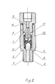
- the metering device works as follows: When the lubricating oil is supplied by the pump, it will enter the inlet channel 2 and enter the cavity 6 of the plunger 5. As a result of the pressure increase, the walls of the cavity 6 are pressed against the walls of the working chamber 3, thereby pressing them The plunger is compressed in the working chamber 3 and functions as a piston. If the pressure of the supplied lubricating oil is greater than the spring force 12, which presses the plunger 5 towards the conical surface 4, the plunger 5 moves to the hollow nut 7, whereby the oil in the working chamber is expelled through the opening 9 of the hollow nut 7. This lasts until the plunger 5 hits the entrance of the central stepped through opening 9 of the hollow nut 7.
- the supplied oil of the plunger is let through the mounted back valve into the opening 9 of the hollow nut 7.
- the same opening 9 is opened by the back valve against the backflow of the oil from its outlet side dosing device. This creates conditions for the valuable filling of the working chamber 3 with a new oil portion.
- the plunger 5 bumps into the conical surface of the dome 17 of the hollow nut 7 with the end of its second cavity 16. Because of the elasticity of the plunger 5, its ends will encompass the conical surface of the dome 17 and they become the oil flow to the passage opening 9 In this position the pump stops working and the pressure in the working chamber 3 is reduced.
- the spring 12 tries to bring the plunger 5 back into the starting position and the ends of the first cavity 6 are drawn together and the oil fills the working chamber 3 out. Proceeding, the ends of the second cavity 16 of the plunger 5 will further encompass the mandrel 17, playing a role of the return valve, holding the beautifully ejected oil so that it does not penetrate into the working chamber 3 before it is filled with the new portion of oil is.
- the ends of the second cavity 16 of the plunger 5 are separated from the walls of the dome 17 and the plunger 5 is brought into the starting position.
- the invention relates to a metering device for fluid, in particular for metering lubricating oils, which ensures an exact and repetitive metering of the fluid portions, regardless of the parameter change of the system in which it is installed, and has a simple and technological construction and unification of the elements of which it is made possible.
- the metering device consists of a body in which the inlet channel and working chamber are formed centrally, which in turn is closed by a hollow nut with a central step-shaped through opening.
- a spring plunger is loosely mounted in the working chamber.
- the transition from the working chamber to the input channel is a conical surface open cavity shaped.
Landscapes
- Engineering & Computer Science (AREA)
- General Engineering & Computer Science (AREA)
- Mechanical Engineering (AREA)
- Physics & Mathematics (AREA)
- Fluid Mechanics (AREA)
- General Physics & Mathematics (AREA)
- Transmission Devices (AREA)
Priority Applications (1)
| Application Number | Priority Date | Filing Date | Title |
|---|---|---|---|
| EP90125555A EP0491988A1 (fr) | 1990-12-27 | 1990-12-27 | Dispositif de dosage pour fluide |
Applications Claiming Priority (1)
| Application Number | Priority Date | Filing Date | Title |
|---|---|---|---|
| EP90125555A EP0491988A1 (fr) | 1990-12-27 | 1990-12-27 | Dispositif de dosage pour fluide |
Publications (1)
| Publication Number | Publication Date |
|---|---|
| EP0491988A1 true EP0491988A1 (fr) | 1992-07-01 |
Family
ID=8204897
Family Applications (1)
| Application Number | Title | Priority Date | Filing Date |
|---|---|---|---|
| EP90125555A Withdrawn EP0491988A1 (fr) | 1990-12-27 | 1990-12-27 | Dispositif de dosage pour fluide |
Country Status (1)
| Country | Link |
|---|---|
| EP (1) | EP0491988A1 (fr) |
Cited By (5)
| Publication number | Priority date | Publication date | Assignee | Title |
|---|---|---|---|---|
| WO1994011644A1 (fr) * | 1992-11-19 | 1994-05-26 | Ina Wälzlager Schaeffler Kg | Element de roulement lineaire |
| EP0855550A1 (fr) * | 1997-01-22 | 1998-07-29 | Alex S.p.A. | Valve doseuse à montage facile |
| CN1312428C (zh) * | 2004-07-23 | 2007-04-25 | 象山县久源润滑件有限公司 | 油脂多点集中定量润滑管路的卸荷方法及自动吸荷装置 |
| CN101985998A (zh) * | 2010-11-26 | 2011-03-16 | 浙江胜祥机械有限公司 | 滴油阀 |
| US9752461B2 (en) | 2013-02-05 | 2017-09-05 | General Electric Technology Gmbh | Steam power plant with a second low-pressure turbine and an additional condensing system |
Citations (2)
| Publication number | Priority date | Publication date | Assignee | Title |
|---|---|---|---|---|
| US1837811A (en) * | 1928-10-15 | 1931-12-22 | Farfall Company | Measuring nipple for lubricating systems |
| GB791455A (en) * | 1954-07-24 | 1958-03-05 | Emmerich Satzger | Dispenser for lubricants |
-
1990
- 1990-12-27 EP EP90125555A patent/EP0491988A1/fr not_active Withdrawn
Patent Citations (2)
| Publication number | Priority date | Publication date | Assignee | Title |
|---|---|---|---|---|
| US1837811A (en) * | 1928-10-15 | 1931-12-22 | Farfall Company | Measuring nipple for lubricating systems |
| GB791455A (en) * | 1954-07-24 | 1958-03-05 | Emmerich Satzger | Dispenser for lubricants |
Cited By (7)
| Publication number | Priority date | Publication date | Assignee | Title |
|---|---|---|---|---|
| WO1994011644A1 (fr) * | 1992-11-19 | 1994-05-26 | Ina Wälzlager Schaeffler Kg | Element de roulement lineaire |
| US5496113A (en) * | 1992-11-19 | 1996-03-05 | Ina Walzlager Schaeffler Kg | Linear bearing element |
| DE4395740C1 (de) * | 1992-11-19 | 1997-06-12 | Schaeffler Waelzlager Kg | Linearlagerelement |
| EP0855550A1 (fr) * | 1997-01-22 | 1998-07-29 | Alex S.p.A. | Valve doseuse à montage facile |
| CN1312428C (zh) * | 2004-07-23 | 2007-04-25 | 象山县久源润滑件有限公司 | 油脂多点集中定量润滑管路的卸荷方法及自动吸荷装置 |
| CN101985998A (zh) * | 2010-11-26 | 2011-03-16 | 浙江胜祥机械有限公司 | 滴油阀 |
| US9752461B2 (en) | 2013-02-05 | 2017-09-05 | General Electric Technology Gmbh | Steam power plant with a second low-pressure turbine and an additional condensing system |
Similar Documents
| Publication | Publication Date | Title |
|---|---|---|
| DE3640669C2 (de) | Fluidabgabevorrichtung | |
| DE69405393T2 (de) | Selbstschliessende anordnung | |
| DE68904004T2 (de) | Spender fuer pastoese produkte, insbesondere fuer zahnpasta. | |
| DE2641171B2 (de) | Schreibgerät | |
| DE10231751B4 (de) | Saug-Druck-Pumpe zum Ausspritzen eines Produkts aus einem Behältnis | |
| DE102007021290A1 (de) | Kolbenpumpe mit abgestuftem Zylinder | |
| DE10334032B4 (de) | Ventileinrichtung | |
| DE1934397C3 (de) | Ventilanordnung | |
| EP0968386B1 (fr) | Presse destinee a comprimer des lubrifiants et cartouche utilisee a cet effet | |
| EP1588071A1 (fr) | Amortisseur con u en particulier pour des pieces de mobilier mobiles | |
| EP0444036B1 (fr) | Stylo applicateur de liquides | |
| DE69814961T2 (de) | Mikropumpe zur Vernebelung von Fluiden | |
| EP0688988B1 (fr) | Valve anti-gouttes | |
| DE2906992C2 (fr) | ||
| EP1631767A1 (fr) | Element distributeur pour des systemes de lubrification | |
| DE3630911C2 (fr) | ||
| EP0542945A1 (fr) | Soupape regulatrice de debit. | |
| DE2651133A1 (de) | Dosierventil fuer unter druck arbeitende schmiersysteme | |
| DE2711208C2 (de) | Vorrichtung zum Dosieren und Abfüllen insbesondere hochviskoser Medien | |
| DE19614446C1 (de) | Fettpresse | |
| DE3525449C2 (de) | Ausgabe-Einrichtung für fließfähige Medien | |
| DE2135635B2 (de) | Vorrichtung zum Spritzgießen plastischer Massen mit einem Einspritzzylinder mit einer Ventilvorrichtung | |
| EP1779023B1 (fr) | Distributeur de dechargement | |
| DE69611937T2 (de) | Teleskopdämpfer mit einem laminatkanal | |
| DE102007011192A1 (de) | Dosiervorrichtung für einen Schmierstoffspender |
Legal Events
| Date | Code | Title | Description |
|---|---|---|---|
| PUAI | Public reference made under article 153(3) epc to a published international application that has entered the european phase |
Free format text: ORIGINAL CODE: 0009012 |
|
| AK | Designated contracting states |
Kind code of ref document: A1 Designated state(s): AT DE FR GB IT |
|
| STAA | Information on the status of an ep patent application or granted ep patent |
Free format text: STATUS: THE APPLICATION IS DEEMED TO BE WITHDRAWN |
|
| 18D | Application deemed to be withdrawn |
Effective date: 19930102 |