EP0492018A1 - Elektrischer Messtransformator - Google Patents
Elektrischer Messtransformator Download PDFInfo
- Publication number
- EP0492018A1 EP0492018A1 EP90403708A EP90403708A EP0492018A1 EP 0492018 A1 EP0492018 A1 EP 0492018A1 EP 90403708 A EP90403708 A EP 90403708A EP 90403708 A EP90403708 A EP 90403708A EP 0492018 A1 EP0492018 A1 EP 0492018A1
- Authority
- EP
- European Patent Office
- Prior art keywords
- transformer
- configuration
- plate
- phase
- range
- Prior art date
- Legal status (The legal status is an assumption and is not a legal conclusion. Google has not performed a legal analysis and makes no representation as to the accuracy of the status listed.)
- Withdrawn
Links
- 238000004804 winding Methods 0.000 claims abstract description 22
- 230000009466 transformation Effects 0.000 claims abstract description 7
- 230000006978 adaptation Effects 0.000 claims description 6
- 238000002955 isolation Methods 0.000 claims description 3
- 238000005070 sampling Methods 0.000 claims description 3
- 230000000007 visual effect Effects 0.000 claims description 2
- 238000012544 monitoring process Methods 0.000 abstract description 6
- 230000004048 modification Effects 0.000 abstract 1
- 238000012986 modification Methods 0.000 abstract 1
- 238000005259 measurement Methods 0.000 description 11
- 238000009434 installation Methods 0.000 description 9
- 239000004020 conductor Substances 0.000 description 2
- 230000001419 dependent effect Effects 0.000 description 2
- 230000008018 melting Effects 0.000 description 2
- 238000002844 melting Methods 0.000 description 2
- 238000010276 construction Methods 0.000 description 1
- 238000010438 heat treatment Methods 0.000 description 1
- 238000004519 manufacturing process Methods 0.000 description 1
- 229910001092 metal group alloy Inorganic materials 0.000 description 1
- 230000007935 neutral effect Effects 0.000 description 1
- 238000007789 sealing Methods 0.000 description 1
Images
Classifications
-
- H—ELECTRICITY
- H01—ELECTRIC ELEMENTS
- H01F—MAGNETS; INDUCTANCES; TRANSFORMERS; SELECTION OF MATERIALS FOR THEIR MAGNETIC PROPERTIES
- H01F38/00—Adaptations of transformers or inductances for specific applications or functions
- H01F38/20—Instruments transformers
- H01F38/22—Instruments transformers for single phase AC
- H01F38/28—Current transformers
-
- H—ELECTRICITY
- H01—ELECTRIC ELEMENTS
- H01F—MAGNETS; INDUCTANCES; TRANSFORMERS; SELECTION OF MATERIALS FOR THEIR MAGNETIC PROPERTIES
- H01F38/00—Adaptations of transformers or inductances for specific applications or functions
- H01F38/20—Instruments transformers
- H01F38/38—Instruments transformers for polyphase AC
Definitions
- the invention relates to improvements made to electrical measurement transformers.
- the present invention applies to transformers, single-phase or polyphase, such as current transformer, capable of adapting an actual electrical value to a value compatible with a measurement, counting, control or monitoring module. It will find its application in the field of electrical construction of such transformers.
- document EP 347.3O4 discloses an electrical measurement transformer, single-phase or polyphase, capable of adapting an actual electrical value to a value compatible with a measurement, counting, control or monitoring module, which allows d '' avoid any risk of human error when adapting the configuration chosen for said transformer.
- this document relates to an electrical measurement transformer, the configuration of which can be adapted as a function of the range of use chosen, that is to say which, when its characteristics have been determined with respect to the 'use, easily adaptable to this use, preventing the risk of incorrect wiring.
- document EP 347,304 describes an electrical measurement transformer, single-phase or polyphase, capable of adapting an actual electrical value il to an i2 compatible value with a measurement, counting, control or monitoring module, which has one side primary, as well as a secondary side, comprising at least one switchable winding, defining a transformation ratio i1 / i2 and consequently its range of use, and which comprises means for adapting the secondary configuration of the transformer according to the range of selected use which carry out at least the switching of the winding (s) according to the chosen range.
- the object of the present invention is to propose improvements for such a current measurement transformer, which makes it possible to increase safety both with respect to a possible manual intervention and for the installation in which it is integrated.
- the improvements to the electrical measurement transformer consist in providing, at the level of said means for adapting the configuration of the transformer, means for causing the short-circuiting of at least part of the secondary winding. during said adaptation.
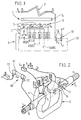
- FIG. 1 schematically represents an embodiment of an electrical transformer for measuring single-phase current, produced according to the teachings of document EP 347,304 and including the improvements of the present application.
- FIG. 2 schematically shows a perspective view of the embodiment of a transformer operating according to the principle of FIG. 1.
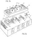
- FIGS. 3a and 3b show a perspective view of a three-phase current transformer produced in accordance with the present invention and of an embodiment of the means of the present invention for adapting the configuration of the transformer.
- the present invention relates to the production of an electrical measurement transformer, single-phase or polyphase, capable of adapting an actual electrical value i1 to a value compatible i2 with a measurement, counting, control or monitoring module, and which is capable of authorizing several transformation reports to authorize an almost universal use of the transformer.
- FIG. 1 illustrates a single-phase current transformer, which, by switching the secondary windings, allows the realization of three different transformation ratios such as for example 100, 200 and 500 primary amps for 5 secondary amps.
- said transformer comprises at least means for adapting the secondary configuration of the transformer as a function of the range of use chosen, which carry out at least the switching of the winding (s) according to the range chosen.
- FIG. 1 illustrates the case of a single-phase current transformer (1) having a primary circuit (2) and a secondary circuit (3) distributed over a magnetic circuit (4).
- the magnetic circuit (4) has a toroidal shape providing a central space capable of receiving at least one passage of a conductor traversed by the phase current, which then defines said primary circuit (2) .
- the configuration illustrated in FIG. 1 with two primary passages, 100/5, 200/5 and 500/5 are obtained by winding the first section with 40 turns, the second section also with 40 turns and the third section with 120 turns.
- the configuration illustrated in FIG. 1 with two primary passages, 100/5, 200/5 and 500/5 are obtained by winding the first section with 40 turns, the second section also with 40 turns and the third section with 120 turns.
- other cases can be envisaged.
- the transformer (1) includes means (6) for adapting the configuration of the transformer (1) according to the range of use chosen, which at least switch over the switch (es) secondary windings (5) according to the chosen range.
- these means (6) for adapting the configuration of the transformer are at least in the form of a plate or element (13), called configuration, wiring support, connectable, pluggable or snap-on on the body of the transformer (1).
- the wiring of this plate or element of configuration depends at least on the selected operating range. Also the means (6) will make it possible to carry out the internal wiring of the secondary winding (s) (5).
- said means (6), and more precisely the plate (13) makes a connection between S2 and S0 or in the case of the choice of the second ratio, in particular 200/5, the connection is made between S0 and S3, and finally in the case of the last report, in particular 500/5, the connection S0 and S4 is then carried out.
- the contacts are made by elastic lyres, able to cooperate with a cylinder or rod made of copper-metal alloy, as for example described in document EP 347,304.
- said means (6) for adapting the configuration of the transformer include means (7) for causing the short-circuiting of at least part of the secondary winding (5) during said adaptation.
- these means (7) consist of at least one short-circuiting contact (8) secured to an actuating member (9), carried by said configuration plate or element (13).
- the contact (8) consists of two contact blades normally closed at rest, that is to say that they allow the secondary (5) to be short-circuited when the configuration plate is not placed on the transformer.
- the transformer will have one contact (8) per phase placed at the level of the body of the transformer (1), this fixed part being wired to the rest of the installation.
- this fixed part being wired to the rest of the installation.
- other arrangements could be considered.
- said configuration plate or element (13) has means of protection (10) against accidental short-circuits of the voltage pick-up circuit of one or more phases, further able to allow isolation. of the voltage circuit during said adaptation or during an intervention on the installation.
- this or these fuses (11) are advantageously carried by said plate or configuration element (13).
- this fuse cooperates with a set of contacts (12) provided at the level of the transformer body (1).
- the fuse associated with each voltage draw tap ensures continuity of the circuit, while if the plate is removed from the transformer, the voltage circuit is isolated from the or of the phases considered.
- said plate or configuration element (13) will be, at least partially at the top of said fuses (11), transparent to allow visual control of the latter.
- Such a control is dependent on the structure of the fuses and it is possible, for example, to use fuses with a high breaking capacity with a melting indicator.
- Figures 3a and 3b show a practical embodiment of the protection means (10) formed of support clips (14) of fuses, integral with the configuration plate (13).
- Such clamps are known to those skilled in the art for supporting fuses.
- one of the legs of the clamp will advantageously be extended by a return suitable for making contact with fixed studs (12) placed opposite the fuses on the body of the transformer.
- the latter will advantageously be at least locked on the transformer body (1) by the intermediate a bolt (15) slidingly mounted on the outside of said plate (13), cooperating with lugs (16) integral with the body of the transformer (1).
- the lugs (16) will protrude relative to the upper plane of the plate (13) and provision will be made lugs (17) at the ends of the bolt (15) capable of entering holes (18) provided for this purpose in the tabs (16).
Landscapes
- Engineering & Computer Science (AREA)
- Power Engineering (AREA)
- Transformers For Measuring Instruments (AREA)
Applications Claiming Priority (1)
| Application Number | Priority Date | Filing Date | Title |
|---|---|---|---|
| FR8916581A FR2655476B2 (fr) | 1988-06-17 | 1989-12-05 | Transformateur electrique de mesure. |
Publications (1)
| Publication Number | Publication Date |
|---|---|
| EP0492018A1 true EP0492018A1 (de) | 1992-07-01 |
Family
ID=9388524
Family Applications (1)
| Application Number | Title | Priority Date | Filing Date |
|---|---|---|---|
| EP90403708A Withdrawn EP0492018A1 (de) | 1989-12-05 | 1990-12-20 | Elektrischer Messtransformator |
Country Status (1)
| Country | Link |
|---|---|
| EP (1) | EP0492018A1 (de) |
Cited By (1)
| Publication number | Priority date | Publication date | Assignee | Title |
|---|---|---|---|---|
| US6865073B2 (en) * | 2003-03-06 | 2005-03-08 | General Electric Company | Panelboard metering arrangement and method of assembly thereof |
Citations (5)
| Publication number | Priority date | Publication date | Assignee | Title |
|---|---|---|---|---|
| FR1352219A (fr) * | 1963-01-02 | 1964-02-14 | Appareillages électriques de transformation et de commande par système interchangeable adapté à un réseau principal | |
| US3512043A (en) * | 1967-11-09 | 1970-05-12 | Asea Ab | Means for short-circuiting the secondary circuit of a current transformer |
| US3564392A (en) * | 1969-09-19 | 1971-02-16 | Gen Electric | Magnetic transducer with means for compensating for temperature changes |
| DE2739499A1 (de) * | 1977-08-30 | 1979-03-08 | Siemens Ag | Kleinstromwandler |
| FR2655476A2 (fr) * | 1988-06-17 | 1991-06-07 | Avocat Jean Paul | Transformateur electrique de mesure. |
-
1990
- 1990-12-20 EP EP90403708A patent/EP0492018A1/de not_active Withdrawn
Patent Citations (5)
| Publication number | Priority date | Publication date | Assignee | Title |
|---|---|---|---|---|
| FR1352219A (fr) * | 1963-01-02 | 1964-02-14 | Appareillages électriques de transformation et de commande par système interchangeable adapté à un réseau principal | |
| US3512043A (en) * | 1967-11-09 | 1970-05-12 | Asea Ab | Means for short-circuiting the secondary circuit of a current transformer |
| US3564392A (en) * | 1969-09-19 | 1971-02-16 | Gen Electric | Magnetic transducer with means for compensating for temperature changes |
| DE2739499A1 (de) * | 1977-08-30 | 1979-03-08 | Siemens Ag | Kleinstromwandler |
| FR2655476A2 (fr) * | 1988-06-17 | 1991-06-07 | Avocat Jean Paul | Transformateur electrique de mesure. |
Cited By (1)
| Publication number | Priority date | Publication date | Assignee | Title |
|---|---|---|---|---|
| US6865073B2 (en) * | 2003-03-06 | 2005-03-08 | General Electric Company | Panelboard metering arrangement and method of assembly thereof |
Similar Documents
| Publication | Publication Date | Title |
|---|---|---|
| BE897691A (fr) | Declencheur mixte differentiel et de court-circuit equipe d'un transformateur d'intensite a tore homopolaire commun | |
| FR2948490A1 (fr) | Dispositif de protection d'une installation electrique contre des surtensions transitoires | |
| FR2607996A1 (fr) | Procede et dispositif pour l'allumage de lampes a decharge | |
| FR2529408A1 (fr) | Montage pour la commutation de charge de transformateurs de reglage a thyristors branches selon un montage antiparallele | |
| EP0347304B1 (de) | Elektrischer Messtransformator | |
| FR2655476A2 (fr) | Transformateur electrique de mesure. | |
| EP0492018A1 (de) | Elektrischer Messtransformator | |
| EP3709333B1 (de) | Elektrisches gerät zur versorgung oder nichtversorgung einer last in abhängigkeit vom ein- oder aus-zustand eines bedienorgans | |
| FR2613493A1 (fr) | Dispositifs de detection de transitions vers l'etat normal dans un bobinage supraconducteur, notamment de generatrice electrique, et de protection d'un tel bobinage | |
| FR2545999A1 (fr) | Dispositif de protection contre les surtensions pour une installation ou un reseau electrique a basse tension | |
| FR2718302A1 (fr) | Sélecteur en charge avec des résistances de passage. | |
| EP0025404B1 (de) | Kurzschlusselement für Serienschaltung | |
| EP0591075B1 (de) | Elektronischer Auslöser für Niederspannungsschutzschalter | |
| FR2827388A1 (fr) | Circuit de mesure du courant homopolaire d'une ligne de courant electrique triphasee | |
| EP1026793B1 (de) | Verbindungsanordnung für einen Schutzschalter | |
| FR2466890A1 (fr) | Dispositif de branchement pour des appareils utilisateurs electriques | |
| EP0579568A1 (de) | Zweipoliger Schalter | |
| FR2627017A1 (fr) | Borne de raccordement d'installation electrique basse tension a transformateur d'intensite et a calibres multiples | |
| FR2653610A1 (fr) | Interrupteur differentiel selectif a courant de defaut. | |
| EP0998003B1 (de) | Differentialschutz mit Mehrfachspannungsprüfkreis | |
| EP0645886A1 (de) | Hochenergiezündgenerator insbesondere für eine Gasturbine | |
| EP0079270A1 (de) | Niederspannungsabzweigschalter mit einem ferngesteuerten Einstellschalter | |
| JPH0877902A (ja) | 電流条件検出装置 | |
| FR2704064A1 (fr) | Bloc de mesure de courant électrique. | |
| FR2562732A1 (fr) | Transformateur de courant pour la protection du neutre d'un appareil electrique tetrapolaire de protection |
Legal Events
| Date | Code | Title | Description |
|---|---|---|---|
| PUAI | Public reference made under article 153(3) epc to a published international application that has entered the european phase |
Free format text: ORIGINAL CODE: 0009012 |
|
| 17P | Request for examination filed |
Effective date: 19920310 |
|
| AK | Designated contracting states |
Kind code of ref document: A1 Designated state(s): AT BE CH DE DK ES GB GR IT LI LU NL SE |
|
| 17Q | First examination report despatched |
Effective date: 19920804 |
|
| STAA | Information on the status of an ep patent application or granted ep patent |
Free format text: STATUS: THE APPLICATION IS DEEMED TO BE WITHDRAWN |
|
| 18D | Application deemed to be withdrawn |
Effective date: 19930706 |