EP0492239A2 - Seitlich stabilisierter Balg zum Umlegen der Wulstlagen für Reifenaufbautrommel - Google Patents
Seitlich stabilisierter Balg zum Umlegen der Wulstlagen für Reifenaufbautrommel Download PDFInfo
- Publication number
- EP0492239A2 EP0492239A2 EP91121050A EP91121050A EP0492239A2 EP 0492239 A2 EP0492239 A2 EP 0492239A2 EP 91121050 A EP91121050 A EP 91121050A EP 91121050 A EP91121050 A EP 91121050A EP 0492239 A2 EP0492239 A2 EP 0492239A2
- Authority
- EP
- European Patent Office
- Prior art keywords
- bladder
- bead
- drum
- tire
- segments
- Prior art date
- Legal status (The legal status is an assumption and is not a legal conclusion. Google has not performed a legal analysis and makes no representation as to the accuracy of the status listed.)
- Granted
Links
Images


Classifications
-
- B—PERFORMING OPERATIONS; TRANSPORTING
- B29—WORKING OF PLASTICS; WORKING OF SUBSTANCES IN A PLASTIC STATE IN GENERAL
- B29D—PRODUCING PARTICULAR ARTICLES FROM PLASTICS OR FROM SUBSTANCES IN A PLASTIC STATE
- B29D30/00—Producing pneumatic or solid tyres or parts thereof
- B29D30/06—Pneumatic tyres or parts thereof (e.g. produced by casting, moulding, compression moulding, injection moulding, centrifugal casting)
- B29D30/38—Textile inserts, e.g. cord or canvas layers, for tyres; Treatment of inserts prior to building the tyre
-
- B—PERFORMING OPERATIONS; TRANSPORTING
- B29—WORKING OF PLASTICS; WORKING OF SUBSTANCES IN A PLASTIC STATE IN GENERAL
- B29D—PRODUCING PARTICULAR ARTICLES FROM PLASTICS OR FROM SUBSTANCES IN A PLASTIC STATE
- B29D30/00—Producing pneumatic or solid tyres or parts thereof
- B29D30/06—Pneumatic tyres or parts thereof (e.g. produced by casting, moulding, compression moulding, injection moulding, centrifugal casting)
- B29D30/08—Building tyres
- B29D30/20—Building tyres by the flat-tyre method, i.e. building on cylindrical drums
- B29D30/32—Fitting the bead-rings or bead-cores; Folding the textile layers around the rings or cores
-
- B—PERFORMING OPERATIONS; TRANSPORTING
- B29—WORKING OF PLASTICS; WORKING OF SUBSTANCES IN A PLASTIC STATE IN GENERAL
- B29D—PRODUCING PARTICULAR ARTICLES FROM PLASTICS OR FROM SUBSTANCES IN A PLASTIC STATE
- B29D30/00—Producing pneumatic or solid tyres or parts thereof
- B29D30/06—Pneumatic tyres or parts thereof (e.g. produced by casting, moulding, compression moulding, injection moulding, centrifugal casting)
- B29D30/08—Building tyres
- B29D30/20—Building tyres by the flat-tyre method, i.e. building on cylindrical drums
- B29D30/24—Drums
- B29D30/26—Accessories or details, e.g. membranes, transfer rings
- B29D2030/2614—Bladders associated with the building drum, e.g. bladders used for the toroidal expansion, bladders for turning-up the plies
-
- B—PERFORMING OPERATIONS; TRANSPORTING
- B29—WORKING OF PLASTICS; WORKING OF SUBSTANCES IN A PLASTIC STATE IN GENERAL
- B29D—PRODUCING PARTICULAR ARTICLES FROM PLASTICS OR FROM SUBSTANCES IN A PLASTIC STATE
- B29D30/00—Producing pneumatic or solid tyres or parts thereof
- B29D30/06—Pneumatic tyres or parts thereof (e.g. produced by casting, moulding, compression moulding, injection moulding, centrifugal casting)
- B29D30/08—Building tyres
- B29D30/20—Building tyres by the flat-tyre method, i.e. building on cylindrical drums
- B29D30/32—Fitting the bead-rings or bead-cores; Folding the textile layers around the rings or cores
- B29D2030/3214—Locking the beads on the drum; details of the drum in the bead locking areas, e.g. drum shoulders
-
- B—PERFORMING OPERATIONS; TRANSPORTING
- B29—WORKING OF PLASTICS; WORKING OF SUBSTANCES IN A PLASTIC STATE IN GENERAL
- B29D—PRODUCING PARTICULAR ARTICLES FROM PLASTICS OR FROM SUBSTANCES IN A PLASTIC STATE
- B29D30/00—Producing pneumatic or solid tyres or parts thereof
- B29D30/06—Pneumatic tyres or parts thereof (e.g. produced by casting, moulding, compression moulding, injection moulding, centrifugal casting)
- B29D30/08—Building tyres
- B29D30/20—Building tyres by the flat-tyre method, i.e. building on cylindrical drums
- B29D30/32—Fitting the bead-rings or bead-cores; Folding the textile layers around the rings or cores
- B29D2030/3221—Folding over means, e.g. bladders or rigid arms
- B29D2030/3228—Folding over means, e.g. bladders or rigid arms using one bladder acting on each side of the drum
Definitions
- the invention relates to tire building equipment and in particular to the tire building drum and inflatable turn-up bladder associated therewith. More particularly, the invention relates to an improved inflatable bladder which reduces or eliminates cord length variation of the tire carcass on the drum by stabilizing the bladder in the area utilized for lifting the reinforced cord fabric of the tire carcass to the tire bead on the tire building drum.
- the various sheets or strip components thereof are laid and placed around a cylindrical drum to build up the carcass.
- these sheets consist of an innerliner, reinforcement strips of calendered fabric, steel, fiberglass or the like, sidewall strips, etc.
- One of the steps in the tire manufacturing process is the coaxial telescopic mounting of a bead ring over the drum around which the ends of the tire carcass are turned up in forming the usual toroidal shape of the final tire.
- These carcass ends are generally turned up by inflatable bladders which are sleeve-like, the ends of which are sealingly mounted on the drum with the intermediate area being inflatable by air for rolling up the ends of the tire carcass around the bead rings.
- the carcass Prior to the inflation of the turn-up bladders, the carcass is moved radially outwardly into engagement with the telescopically located bead rings by a plurality of circularly arranged bead lock segments which are mounted on the drum and are expanded radially outwardly by pressurized air, mechanical linkages or the like.
- U.S. Patent No. 3,101,289 discloses a method of making a resilient reinforced diaphragm for use on a tire building drum wherein the diaphragm has lateral zones and a central zone, with the central zone having reinforcing material embedded therein. Upon expansion of a pair of rings, the bead wires are pressed into grooves formed in the rings with the reinforcing material in the central zone, being used to provide radial stability to the diaphragm.
- U.S. Patent No. 3,418,192 shows the use of a bellows secured to the drum at the enlarged bead portions thereof in a tire building drum.
- U.S. Patent No. 3,989,564 discloses a method and apparatus for forming a tire using a building drum that employs an inflatable bladder wherein the expandable sleeve thereof has an inflatable portion that is formed from a rubber material without cord reinforcement and is retained in a slot by an integral flange. This is a type of construction utilized for many tire building drums for holding the sleeve on the center of the drum when radially expanding the drum.
- U.S. Patent No. 4,081,310 discloses an expandable bead grip wherein one bead end portion of the bladder is retained in a groove formed in the expandable bead ring.
- U.S. Patent No. 4,830,693 shows another inflatable bladder used in a tire building drum which has reinforcing material embedded in a portion thereof.
- U.S. Patent No. 4,450,025 discloses a method and apparatus for encasing a tire bead wherein an inflatable bladder is positioned over drum segments via a plurality of projections spaced at intervals around a circumference of the drum with projections fitting into grooves. Even though the projections prevent axial movement of the bladder, it does not solve the same problem as that solved by the present invention, that is, cord length fabric variations upon outward expansion of the bead lock segments. In this prior art patent, the bead cover strip does not move laterally and the projections are only spaced at intervals around the circumference of the drum.
- Objectives of the invention include providing an improved tire building drum and inflatable bead turn-up bladders which reduce or eliminate cord length variation in the reinforcing fabric of the tire carcass by stabilizing the turn-up bladder which lifts the reinforced cord fabric to the tire bead when the latter is telescopically mounted on the tire building drum.
- a further objective of the invention is to provide such an inflatable bladder wherein the ends thereof are attached to the drum in the usual manner but is provided with an additional integrally formed annular rib which is seated into grooves or slots formed in the bead lock segments, preventing lateral displacement of the bladder and supported carcass ply material, as the bead locks are expanded radially outwardly into the bead ring.
- Still another objective is to provide such an improved inflatable bladder having a stretch zone free of internal reinforcing material which is located between the retaining rib and one end of the bladder, to permit the bladder to stretch in this area while stabilizing the bladder area and supported carcass above the bead lock segments to prevent the undesirable axial movement and resulting variations in the reinforcing fabric.
- Still another objective of the invention is to provide such an improved inflatable bladder in which the retaining rib may be formed either on the inner or outer surfaces of the turn-up bladder at various locations between the bladder ends, enabling the bladder to be utilized with various configured tire building drums without affecting the manner of operation and construction of the drums except for the replacement of the heretofore used bead lock segments with new segments having a groove formed therein.
- a further objective of the invention is to provide such an improved inflatable bead turn-up bladder in which the stabilizing rib is preferably formed integrally with the bladder and of the same elastomeric material, thereby enabling the production of the bladder to be achieved in a usual low cost manufacturing operation.
- a still further objective of the invention is to provide an inflatable bladder which eliminates the floating of the bladder over the bead locks as the locks are expanded radially outwardly by securing the bladder to the bead locks, preventing movement of the tire carcass therewith; and in which certain areas of the bladder are reinforced so as not to allow any stretch in the critical areas of the bladder while allowing the bladder material from the securement rib to the inboard end of the bladder to stretch as the bead lock segments are expanded outwardly.
- the improved inflatable elastomeric bead turn-up bladder in combination with a tire building drum of the type having a plurality of radially movable segments circularly arranged coaxial of the drum for gripping a bead against the tire carcass, in which the inflatable bead turn-up elastomeric bladder is disposed coaxially of the drum and extends generally axially outwardly with respect to a centerline of the drum, with a portion of the bladder coaxially overlying the movable segments. Furthermore, the segments are formed with slots or recesses which provide an annular groove about the circularly arranged bead lock segments.
- the bladder includes a pair of circular ends sealingly secured on the drum to form an inflatable chamber therebetween, with the bladder having rib means attached in the annular groove of the bead lock segments for reducing axial movement of that portion of the bladder lying coaxially adjacent the segments upon radial outward movement of the segments, with the bladder having a stretch zone free of internal reinforcement between the rib means and one of the bladder ends.
- FIGS. 1 and 2 show a prior art tire building drum and associated inflatable bead turn-up bladder mounted thereon.
- Tire building drum 1 is of a usual construction and includes a main drum body 3 having a collar plate 4 which locks a first ribbed end 5 of usual inflatable bead turn-up bladder 2, within a groove 6 thereof, in an air tight sealing relationship.
- a pair of stop rings 8 are mounted on drum body 3 in an axial spaced relationship forming a channel 7 therebetween.
- a plurality of bead lock segments, indicated generally at 9, are radially slidably mounted in channel 7.
- bead lock segments 9 are moved radially outwardly by pressurized air filling a chamber 10, in combination with an inflatable elastomeric chamber 11 which engages bottom surface 12 of each segment 9.
- An annular elastomeric band 15 is located within a complementary shaped channel 16 formed in each segment 9, providing a return spring for the segments.
- Bladder 2 has a second ribbed end 17 which is locked in an airtight sealing position on drum body 3 by another collar plate 18.
- elastomeric material portion 19 of bladder 2 extends between bladder ends 5 and 17 forming an elastomeric sleeve-like member which provides an inflation chamber which when filled with compressed air, will cause material portion 19 to expand upwardly outwardly in the general direction of arrow A, in a somewhat similar manner as shown in U.S. Patent No. 3,989,564, for moving the ends of the tire carcass, indicated in phantom lines at 20, around a bead ring 21 which is located coaxially over the carcass end and radially aligned with the center of bead lock segments 9.
- Bead rings 21 may have a variety of configurations and usually consists of a wire ring 22 generally encased within an elastomeric material, together with bead apex strip 23 extending outwardly therefrom.
- tire drum 1, turn-up bladder 2 and drum body 3 are well known in the art as shown in FIGS. 1 and 2, and illustrates the problem that occurs in such tire building equipment, which is solved by the present invention.
- FIG. 1 shows bladder 2 in a deflated position and bead lock segments 9 in retracted position, with a tire carcass 20 overlying the bead locks prior to the bead lock segments 9 being expanded radially outwardly as shown in FIG. 2, so as to bring the tire carcass and bladder into engagement with coaxially mounted bead ring 21.
- the undesirable lateral shifting of the bladder is illustrated by means of a point 25 on bladder 2, which when at rest in FIG. 1 is positioned above one particular location of bead segment 9.
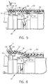
- FIGS. 3 and 4 show the use of the improved inflatable bladder of the invention, which is indicated generally at 30 and shown particularly in FIG. 7, mounted on the same general type of tire building drum 1 as that shown in FIGS. 1 and 2.
- a continuous annular rib 31 is formed, on the inside surface 32, of bladder material 33, which extends between ribbed bladder ends 34 and 35. Ends 34 and 35 sealingly mount bladder 30 on drum body 3 by collar plates 4 and 18, as discussed above with respect to bladder ends 5 and 17.
- annular elastomeric return ring 37 is formed with a slot or groove 38 therein.
- Groove 38 is complementary in shape and size to that of annular rib 31 for receiving and seating rib 31 therein when bead lock segments 9 are expanded radially outwardly as shown in FIG. 4.
- Groove 38 in return ring 37 preferably is formed in one side thereof, and cooperates with an end portion 39 of bead lock segment 9.
- groove 38 could be formed entirely within return ring 37 without affecting the concept of the invention.
- internal reinforcing material or cords 40 preferably extend throughout bladder material 33 beginning at rib 31 and continuing into bladder end rib 35.
- a stretch zone 41 is formed from rib 31 to the opposite rib end 34 of bladder 30, which is free of any internal reinforcing material. As shown in FIG. 4, it is stretch zone 41 which will stretch as bead lock segments 9 are moved radially outwardly, since bladder end 34 is fixed as well as rib 31, permitting the stretch to occur in this zone or area. This stretch zone prevents any lateral movement of the bladder area above bead lock segments 9 as illustrated by point 44 marked thereon.
- this lateral stabilization of the bladder area above bead lock segments 9, will also maintain the tire carcass 20, and in particular the reinforcing material or cords contained therein, also laterally stabilized, preventing the undesirable distortion or movement of these internal reinforcing cords.
- tire drum 1 and inflatable bladder 30 are similar to that with respect to FIGS. 1 and 2.
- pressurized air then fills bladder 30 and the expansion chamber 43 formed between the folds of the bladder. This will cause portions of the bladder to move upwardly to wrap the ends of the carcass about the bead ring.
- the centerline of the drum is to the left of the bead lock segments as shown in FIGS. 4 and 5, and the bladder will move in the general direction of arrow A (FIG. 4).
- FIGS. 5 and 6 A slightly modified form of the invention is shown in FIGS. 5 and 6 in which a different type of tire building drum 45 is used with a modified bladder 50.
- Drum 45 utilizes a mechanically actuated linkage indicated generally at 46, for moving bead lock segments 47 radially outwardly toward bead ring 21.
- bead lock segments 47 preferably are formed of metal without any elastomeric return ring, and are formed with slots or grooves 48 for receiving an annular rib portion 49 of inflatable bladder 50 therein. Segments 47 are moved radially outwardly and inwardly by a member 51 on which segments 47 are mounted, upon movement of the mechanical linkage.
- Bladder 50 is generally similar to bladder 30 discussed above, except that annular rib 49 is formed on an outer surface of the bladder and the ribbed bladder end 52 is clamped generally adjacent the other ribbed bladder end 53 axially outboard of rib 49.
- the centerline of the tire building drum is to the left of FIGS. 5 and 6 as was the location of the centerline of the tire building drum of FIGS. 3 and 4.
- Pressurized air is moved through an inlet line 54 of tire building drum 45 in a well known manner, for inflating bladder 50.
- Bladder ends 52 and 53 are sealingly mounted on the tire building drum also in a manner well known in the art.
- a stretch zone 56 is located between rib 49 and bladder end 52 and is free of any internal reinforcing material.
- the remainder of the bladder preferably has a reinforcing material 55 embedded therein, although the same is not necessary for the successful use of the improved bladder.
- modified tire building drum 45 and bladder 50 in the same manner as by tire building drum 1 and bladder 30, since that area of bladder 50 located coaxial with and radially outwardly from bead lock segments 49 is laterally stabilized by the locking of rib 49 within the grooves of segments 47 to prevent any lateral or axial movement of the bladder and overlying tire carcass upon being expanded into engagement with bead ring 21, in combination with stretch zone 56.
- the improved bead turn-up bladder is formed with a stabilizing rib, preferably formed integrally with the bladder and of the same elastomeric material, which enables the rib and that portion of the bladder material adjacent thereto, to be laterally stabilized by locking the annular rib within an annular groove formed by the individual slots of the circularly arranged bead lock segments.
- a stabilizing rib preferably formed integrally with the bladder and of the same elastomeric material, which enables the rib and that portion of the bladder material adjacent thereto, to be laterally stabilized by locking the annular rib within an annular groove formed by the individual slots of the circularly arranged bead lock segments.
- the inflatable bead turn-up bladder is simplified, provides an effective, safe, inexpensive, and efficient device which achieves all the enumerated objectives, provides for eliminating difficulties encountered with prior devices, and solves problems and obtains new results in the art.
Landscapes
- Engineering & Computer Science (AREA)
- Mechanical Engineering (AREA)
- Textile Engineering (AREA)
- Tyre Moulding (AREA)
- Fluid-Damping Devices (AREA)
Applications Claiming Priority (2)
| Application Number | Priority Date | Filing Date | Title |
|---|---|---|---|
| US633737 | 1990-12-24 | ||
| US07/633,737 US5141588A (en) | 1990-12-24 | 1990-12-24 | Laterally stabilized inflatable bead turn-up bladder for tire building drum |
Publications (3)
| Publication Number | Publication Date |
|---|---|
| EP0492239A2 true EP0492239A2 (de) | 1992-07-01 |
| EP0492239A3 EP0492239A3 (en) | 1993-03-03 |
| EP0492239B1 EP0492239B1 (de) | 1995-03-29 |
Family
ID=24540914
Family Applications (1)
| Application Number | Title | Priority Date | Filing Date |
|---|---|---|---|
| EP91121050A Expired - Lifetime EP0492239B1 (de) | 1990-12-24 | 1991-12-09 | Seitlich stabilisierter Balg zum Umlegen der Wulstlagen für Reifenaufbautrommel |
Country Status (8)
| Country | Link |
|---|---|
| US (1) | US5141588A (de) |
| EP (1) | EP0492239B1 (de) |
| JP (1) | JP3228771B2 (de) |
| KR (1) | KR100193995B1 (de) |
| CA (1) | CA2058357A1 (de) |
| DE (1) | DE69108532T2 (de) |
| ES (1) | ES2069806T3 (de) |
| MX (1) | MX9102595A (de) |
Cited By (3)
| Publication number | Priority date | Publication date | Assignee | Title |
|---|---|---|---|---|
| WO2000012297A1 (en) * | 1998-09-01 | 2000-03-09 | The Goodyear Tire & Rubber Company | Tire building method and apparatus |
| EP1798022A1 (de) * | 2005-12-14 | 2007-06-20 | Societe de Technologie Michelin | Membran für das Umwenden im unteren Bereich |
| WO2020055237A1 (en) * | 2018-09-11 | 2020-03-19 | Vmi Holland B.V. | Tire building drum with a bladder or sleeve |
Families Citing this family (14)
| Publication number | Priority date | Publication date | Assignee | Title |
|---|---|---|---|---|
| US5433814A (en) * | 1992-06-29 | 1995-07-18 | Yasushi Nojiri | Green tire building apparatus |
| US5300180A (en) * | 1993-06-10 | 1994-04-05 | Bridgestone/Firestone, Inc. | Magnetic tire bead setter |
| US5440139A (en) * | 1994-03-02 | 1995-08-08 | Grumman Aerospace Corporation | Circuit for optically coupling a cryobenic detector array with processing circuitry and for increasing the dynamic range of detection |
| US6585022B1 (en) * | 1998-09-01 | 2003-07-01 | The Goodyear Tire And Rubber Company | Tire building method and apparatus |
| US6972061B1 (en) * | 1999-12-06 | 2005-12-06 | The Goodyear Tire & Rubber Company | Compound apex for vehicle tire |
| US7082336B2 (en) * | 2003-06-04 | 2006-07-25 | Synecor, Llc | Implantable intravascular device for defibrillation and/or pacing |
| JP4974047B2 (ja) * | 2006-07-25 | 2012-07-11 | 横浜ゴム株式会社 | 未加硫タイヤの成形方法及びその装置 |
| US8746318B2 (en) * | 2010-03-15 | 2014-06-10 | Clinton Robert Clark | Tire bead seating method and apparatus |
| CN104589681A (zh) * | 2013-11-01 | 2015-05-06 | 福建建阳龙翔科技开发有限公司 | 胶囊卡盘式成型鼓 |
| JP6769235B2 (ja) * | 2016-10-21 | 2020-10-14 | 横浜ゴム株式会社 | タイヤ成形用ブラダー及びそれを用いたタイヤ成形方法 |
| JP6769236B2 (ja) * | 2016-10-21 | 2020-10-14 | 横浜ゴム株式会社 | タイヤ成形用ブラダー及びそれを用いたタイヤ成形方法 |
| KR102102429B1 (ko) * | 2018-09-19 | 2020-04-20 | 금호타이어 주식회사 | 성형 블래더 |
| US12023488B2 (en) | 2020-08-17 | 2024-07-02 | Ebr Systems, Inc. | Implantable stimulation assemblies having tissue engagement mechanisms, and associated systems and methods |
| US12350497B2 (en) | 2022-02-10 | 2025-07-08 | Ebr Systems, Inc. | Tissue stimulation systems and methods, such as for pacing cardiac tissue |
Family Cites Families (13)
| Publication number | Priority date | Publication date | Assignee | Title |
|---|---|---|---|---|
| US3101289A (en) * | 1959-04-24 | 1963-08-20 | Pirelli | Method of making expansible tubular diaphragms for tire building drums |
| DE1276911B (de) * | 1961-12-15 | 1968-09-05 | Continental Gummi Werke Ag | Reifenaufbautrommel mit einem aus Segmenten bestehenden, im Durchmesser vergroesserbaren Trommelkoerper |
| DE1262582B (de) * | 1964-04-27 | 1968-03-07 | Continental Gummi Werke Ag | Segmenttrommel zum Aufbauen von Reifenkarkassen |
| US4081310A (en) * | 1975-06-25 | 1978-03-28 | Uniroyal, Inc. | Bead grip ring |
| US3989564A (en) * | 1975-08-04 | 1976-11-02 | The Goodyear Tire & Rubber Company | Building a closed torus tire |
| US4087307A (en) * | 1976-08-30 | 1978-05-02 | The Goodyear Tire & Rubber Company | Inflatable bladder for a tire building drum |
| US4226656A (en) * | 1979-04-02 | 1980-10-07 | The Goodyear Tire & Rubber Company | Tire carcass assembly |
| US4239579A (en) * | 1979-05-25 | 1980-12-16 | The Goodyear Tire & Rubber Company | Tire building drum |
| US4450025A (en) * | 1983-01-31 | 1984-05-22 | The General Tire & Rubber Company | Method and apparatus for wrapping a tire bead ring |
| US4498948A (en) * | 1983-08-24 | 1985-02-12 | Gencorp Inc. | Bead locking device of a tire building drum |
| US4584038A (en) | 1984-01-13 | 1986-04-22 | Nrm Corporation | Tire building method |
| US4830693A (en) * | 1985-11-08 | 1989-05-16 | Bridgestone Corporation | Method for forming a tire around a bead |
| JP3103729U (ja) | 2004-03-03 | 2004-08-26 | 株式会社東洋セラミックス | 電子レンジ加熱用皿 |
-
1990
- 1990-12-24 US US07/633,737 patent/US5141588A/en not_active Expired - Lifetime
-
1991
- 1991-12-09 ES ES91121050T patent/ES2069806T3/es not_active Expired - Lifetime
- 1991-12-09 EP EP91121050A patent/EP0492239B1/de not_active Expired - Lifetime
- 1991-12-09 DE DE69108532T patent/DE69108532T2/de not_active Expired - Fee Related
- 1991-12-17 MX MX9102595A patent/MX9102595A/es not_active IP Right Cessation
- 1991-12-19 KR KR1019910023405A patent/KR100193995B1/ko not_active Expired - Fee Related
- 1991-12-19 JP JP35396991A patent/JP3228771B2/ja not_active Expired - Fee Related
- 1991-12-23 CA CA002058357A patent/CA2058357A1/en not_active Abandoned
Cited By (8)
| Publication number | Priority date | Publication date | Assignee | Title |
|---|---|---|---|---|
| WO2000012297A1 (en) * | 1998-09-01 | 2000-03-09 | The Goodyear Tire & Rubber Company | Tire building method and apparatus |
| EP1798022A1 (de) * | 2005-12-14 | 2007-06-20 | Societe de Technologie Michelin | Membran für das Umwenden im unteren Bereich |
| US7740040B2 (en) | 2005-12-14 | 2010-06-22 | Michelin Recherche Et Technique S.A. | Bottom zone turn-up membrane |
| WO2020055237A1 (en) * | 2018-09-11 | 2020-03-19 | Vmi Holland B.V. | Tire building drum with a bladder or sleeve |
| NL2021600B1 (en) * | 2018-09-11 | 2020-05-01 | Vmi Holland Bv | Tire building drum with a bladder or sleeve |
| KR20210050552A (ko) * | 2018-09-11 | 2021-05-07 | 브이엠아이 홀랜드 비.브이. | 블래더 또는 슬리브를 갖는 타이어 성형 드럼 |
| KR102429270B1 (ko) | 2018-09-11 | 2022-08-03 | 브이엠아이 홀랜드 비.브이. | 블래더 또는 슬리브를 갖는 타이어 성형 드럼 |
| US11518128B2 (en) | 2018-09-11 | 2022-12-06 | Vmi Holland B.V. | Tire building drum with a bladder or sleeve |
Also Published As
| Publication number | Publication date |
|---|---|
| DE69108532T2 (de) | 1995-08-03 |
| DE69108532D1 (de) | 1995-05-04 |
| US5141588A (en) | 1992-08-25 |
| CA2058357A1 (en) | 1992-06-25 |
| ES2069806T3 (es) | 1995-05-16 |
| KR920011699A (ko) | 1992-07-24 |
| EP0492239B1 (de) | 1995-03-29 |
| EP0492239A3 (en) | 1993-03-03 |
| JPH04303632A (ja) | 1992-10-27 |
| MX9102595A (es) | 1992-06-01 |
| KR100193995B1 (ko) | 1999-06-15 |
| JP3228771B2 (ja) | 2001-11-12 |
Similar Documents
| Publication | Publication Date | Title |
|---|---|---|
| EP0492239B1 (de) | Seitlich stabilisierter Balg zum Umlegen der Wulstlagen für Reifenaufbautrommel | |
| US4008743A (en) | Pneumatic tire with puncture resistance internal safety structure | |
| EP0015224B1 (de) | Aufbau und Formung eines Reifens | |
| CA2121159C (en) | Contoured tire building drum and method of building an extended mobility tire | |
| EP1084027B1 (de) | Verfahren zur herstellung eines fahrzeugreifens, ein damit hergestellter reifen und einen solchen reifen enthaltendes fahrzeugrad | |
| US3833444A (en) | Tire building apparatus of building tires | |
| US6488797B1 (en) | First stage run flat tire building drum and method of using same | |
| US3400746A (en) | Pneumatic expansible tire having resiliently folding sidewalls | |
| US3386875A (en) | Expandable tire building bladder apparatus | |
| EP0502625B1 (de) | Radialreifen | |
| EP0294484B1 (de) | Verfahren zur herstellung eines radialreifens | |
| EP0016570B1 (de) | Reifenkonfektioniermaschine | |
| EP0140483B1 (de) | Wulstumschlagvorrichtung | |
| US4249979A (en) | Ply folding bladder | |
| US5433814A (en) | Green tire building apparatus | |
| US4177851A (en) | Foldable spare tire | |
| US4247356A (en) | Expandable tire building drum with improved bladder | |
| US3901750A (en) | Method of building dual chambered tires | |
| EP0509095B1 (de) | Rohreifenaufbaumaschine | |
| EP0317318B1 (de) | Verfahren zur Herstellung von Reifen | |
| EP0638410B1 (de) | Verfahren zur Herstellung von Radialluftreifen | |
| KR100588397B1 (ko) | 차량 휠용 타이어 제조방법, 상기 방법에 의해 제조되는 타이어 및 상기 타이어로 이루어지는 차량용 휠 | |
| JP2000062417A (ja) | 特に一体のリムと、特にランフラットに適したチュ―ブレス空気タイヤを備えた車輪 |
Legal Events
| Date | Code | Title | Description |
|---|---|---|---|
| PUAI | Public reference made under article 153(3) epc to a published international application that has entered the european phase |
Free format text: ORIGINAL CODE: 0009012 |
|
| AK | Designated contracting states |
Kind code of ref document: A2 Designated state(s): DE ES FR GB IT LU |
|
| PUAL | Search report despatched |
Free format text: ORIGINAL CODE: 0009013 |
|
| AK | Designated contracting states |
Kind code of ref document: A3 Designated state(s): DE ES FR GB IT LU |
|
| 17P | Request for examination filed |
Effective date: 19930205 |
|
| 17Q | First examination report despatched |
Effective date: 19940804 |
|
| GRAA | (expected) grant |
Free format text: ORIGINAL CODE: 0009210 |
|
| AK | Designated contracting states |
Kind code of ref document: B1 Designated state(s): DE ES FR GB IT LU |
|
| REF | Corresponds to: |
Ref document number: 69108532 Country of ref document: DE Date of ref document: 19950504 |
|
| REG | Reference to a national code |
Ref country code: ES Ref legal event code: FG2A Ref document number: 2069806 Country of ref document: ES Kind code of ref document: T3 |
|
| ITF | It: translation for a ep patent filed | ||
| ET | Fr: translation filed | ||
| PLBE | No opposition filed within time limit |
Free format text: ORIGINAL CODE: 0009261 |
|
| STAA | Information on the status of an ep patent application or granted ep patent |
Free format text: STATUS: NO OPPOSITION FILED WITHIN TIME LIMIT |
|
| 26N | No opposition filed | ||
| REG | Reference to a national code |
Ref country code: GB Ref legal event code: IF02 |
|
| PGFP | Annual fee paid to national office [announced via postgrant information from national office to epo] |
Ref country code: LU Payment date: 20060927 Year of fee payment: 16 |
|
| PGFP | Annual fee paid to national office [announced via postgrant information from national office to epo] |
Ref country code: GB Payment date: 20061106 Year of fee payment: 16 |
|
| PGFP | Annual fee paid to national office [announced via postgrant information from national office to epo] |
Ref country code: FR Payment date: 20061201 Year of fee payment: 16 |
|
| PGFP | Annual fee paid to national office [announced via postgrant information from national office to epo] |
Ref country code: ES Payment date: 20061220 Year of fee payment: 16 |
|
| PGFP | Annual fee paid to national office [announced via postgrant information from national office to epo] |
Ref country code: DE Payment date: 20061229 Year of fee payment: 16 |
|
| PGFP | Annual fee paid to national office [announced via postgrant information from national office to epo] |
Ref country code: IT Payment date: 20061231 Year of fee payment: 16 |
|
| GBPC | Gb: european patent ceased through non-payment of renewal fee |
Effective date: 20071209 |
|
| PG25 | Lapsed in a contracting state [announced via postgrant information from national office to epo] |
Ref country code: DE Free format text: LAPSE BECAUSE OF NON-PAYMENT OF DUE FEES Effective date: 20080701 |
|
| REG | Reference to a national code |
Ref country code: FR Ref legal event code: ST Effective date: 20081020 |
|
| PG25 | Lapsed in a contracting state [announced via postgrant information from national office to epo] |
Ref country code: GB Free format text: LAPSE BECAUSE OF NON-PAYMENT OF DUE FEES Effective date: 20071209 |
|
| REG | Reference to a national code |
Ref country code: ES Ref legal event code: FD2A Effective date: 20071210 |
|
| PG25 | Lapsed in a contracting state [announced via postgrant information from national office to epo] |
Ref country code: ES Free format text: LAPSE BECAUSE OF NON-PAYMENT OF DUE FEES Effective date: 20071210 Ref country code: FR Free format text: LAPSE BECAUSE OF NON-PAYMENT OF DUE FEES Effective date: 20071231 |
|
| PG25 | Lapsed in a contracting state [announced via postgrant information from national office to epo] |
Ref country code: IT Free format text: LAPSE BECAUSE OF NON-PAYMENT OF DUE FEES Effective date: 20071209 Ref country code: LU Free format text: LAPSE BECAUSE OF NON-PAYMENT OF DUE FEES Effective date: 20071209 |