EP0492437B1 - Polarisationsunabhängiger optischer Isolator - Google Patents
Polarisationsunabhängiger optischer Isolator Download PDFInfo
- Publication number
- EP0492437B1 EP0492437B1 EP19910121786 EP91121786A EP0492437B1 EP 0492437 B1 EP0492437 B1 EP 0492437B1 EP 19910121786 EP19910121786 EP 19910121786 EP 91121786 A EP91121786 A EP 91121786A EP 0492437 B1 EP0492437 B1 EP 0492437B1
- Authority
- EP
- European Patent Office
- Prior art keywords
- polarization
- optical
- optical isolator
- paths
- dependent
- Prior art date
- Legal status (The legal status is an assumption and is not a legal conclusion. Google has not performed a legal analysis and makes no representation as to the accuracy of the status listed.)
- Expired - Lifetime
Links
- 230000003287 optical effect Effects 0.000 title claims description 217
- 230000010287 polarization Effects 0.000 title claims description 105
- 230000001419 dependent effect Effects 0.000 claims 23
- 230000000694 effects Effects 0.000 description 12
- GWEVSGVZZGPLCZ-UHFFFAOYSA-N Titan oxide Chemical compound O=[Ti]=O GWEVSGVZZGPLCZ-UHFFFAOYSA-N 0.000 description 3
- 230000005540 biological transmission Effects 0.000 description 2
- 238000002955 isolation Methods 0.000 description 2
- 239000004065 semiconductor Substances 0.000 description 1
- 230000002194 synthesizing effect Effects 0.000 description 1
Images


Classifications
-
- G—PHYSICS
- G02—OPTICS
- G02F—OPTICAL DEVICES OR ARRANGEMENTS FOR THE CONTROL OF LIGHT BY MODIFICATION OF THE OPTICAL PROPERTIES OF THE MEDIA OF THE ELEMENTS INVOLVED THEREIN; NON-LINEAR OPTICS; FREQUENCY-CHANGING OF LIGHT; OPTICAL LOGIC ELEMENTS; OPTICAL ANALOGUE/DIGITAL CONVERTERS
- G02F1/00—Devices or arrangements for the control of the intensity, colour, phase, polarisation or direction of light arriving from an independent light source, e.g. switching, gating or modulating; Non-linear optics
- G02F1/01—Devices or arrangements for the control of the intensity, colour, phase, polarisation or direction of light arriving from an independent light source, e.g. switching, gating or modulating; Non-linear optics for the control of the intensity, phase, polarisation or colour
- G02F1/09—Devices or arrangements for the control of the intensity, colour, phase, polarisation or direction of light arriving from an independent light source, e.g. switching, gating or modulating; Non-linear optics for the control of the intensity, phase, polarisation or colour based on magneto-optical elements, e.g. exhibiting Faraday effect
- G02F1/093—Devices or arrangements for the control of the intensity, colour, phase, polarisation or direction of light arriving from an independent light source, e.g. switching, gating or modulating; Non-linear optics for the control of the intensity, phase, polarisation or colour based on magneto-optical elements, e.g. exhibiting Faraday effect used as non-reciprocal devices, e.g. optical isolators, circulators
-
- G—PHYSICS
- G02—OPTICS
- G02F—OPTICAL DEVICES OR ARRANGEMENTS FOR THE CONTROL OF LIGHT BY MODIFICATION OF THE OPTICAL PROPERTIES OF THE MEDIA OF THE ELEMENTS INVOLVED THEREIN; NON-LINEAR OPTICS; FREQUENCY-CHANGING OF LIGHT; OPTICAL LOGIC ELEMENTS; OPTICAL ANALOGUE/DIGITAL CONVERTERS
- G02F2203/00—Function characteristic
- G02F2203/06—Polarisation independent
Definitions
- This invention relates to an optical isolator and, more particularly, to a polarization-independent type optical isolator capable of functioning without consideration for a plane of polarization of incident light.
- Fig. 1 shows an example of the arrangement of a conventional optical isolator.
- This optical isolator is such that after incident light passes through a first polarizer 1, the plane of polarization of the incident light is rotated at angle of 45° by a Faraday rotator 2 and the incident light further passes through a second polarizer 3 which has the plane of polarization inclined at 45° with respect to the first polarizer.
- a first polarizer 1 For return light reflected in a direction opposite to the incident light, on the other hand, only a component of the light which coincides in plane of polarization with the second polarizer 3 traverses the second polarizer 3 and then the plane of polarization thereof is further rotated at 45° by the Faraday rotator 2.
- the reflected return light which has traversed the Faraday rotator is such that the plane of polarization is rotated at 90° with respect to the first polarizer 1, and thereby the reflected return light cannot reach the entrance side of the incident light.
- the reflected return light in the opposite direction is blocked and the function of the optical isolator of this type is thus performed.
- the isolator of the arrangement depicted in Fig. 1 is constructed in a plural, a higher effect of isolation can be brought about.
- reference numeral 4 represents an optical isolator unit comprising two optical isolators, each of which has the arrangement shown in Fig. 1, that is, two sets of optical isolator blocks, cemented in series, each including the first polarizer 1, the Faraday rotator 2, and the second polarizer 3.
- a first optical system I which will be described later, is arranged on the front side of the optical isolator unit 4, namely, on the incidence side, and a second optical system II which will also be described later, on the emergence side.
- the first optical system I comprises an optical member 5, like a birefringent plate made of TiO 2 (rutile) for instance, capable of splitting incident light into two polarized components and also of synthesizing the two polarized components and a polarizing rotator 6, such as a half-wave plate by way of example, inserted only in an optical path b of one of the polarized components split by the optical member 5.
- the second optical system II comprises a polarizing rotator 7, equivalent to the polarizing rotator 6, inserted only in an optical path a of the other of the polarized components which have traversed the optical isolator unit 4, and an optical member 8 equivalent to the optical member 5.
- the polarizing rotator 6 is arranged so that the plane of polarization of the polarized component split by the optical member 5 and traveling along the optical path b is rotated at an angle of 90° to coincide with that of the polarized component traveling along the optical path a.
- the polarizer 1 on the incidence side is disposed so that the plane of polarization coincides with those of the polarized components traveling along the optical paths a and b.
- the polarizing rotator 7 and the optical member 8 are arranged so that the polarized components, after passage through the isolator unit 4, traveling along the optical paths a and b can be combined.
- the two polarized components whose planes of polarization are both rotated at 90° in the optical isolator unit 4, enter the second optical system II.
- the plane of polarization of the polarized component following the optical path a is rotated at 90° by the polarizing rotator 7. Consequently, the polarized components traveling along the optical paths a and b reach such a state that the planes of polarization intersect again at right angles, are again synthesized by the optical member 8, and emerge from the second optical system II.
- the laser light incident on the optical member 8 from the right of the second optical system II is split, by the optical member 8, into the polarized components having the planes of polarization making right angles with each other, which travel leftward along the optical paths a and b and are incident on the optical isolator unit 4.
- Such polarized components are blocked to travel by the behavior of the optical isolator unit 4 and hence cannot emerge therefrom toward the first optical system I.
- the performance of the optical isolator unit 4 can be effectively exerted.
- Fig. 3 shows the second embodiment of the present invention.
- This embodiment is different from the first embodiment in arrangement that the optical isolator unit 4 is constructed so that four sets of optical isolator blocks, each of which has the arrangement shown in Fig. 1, are connected in series and the plane of polarization on the incident side is equal to that on the emergence side.
- the second embodiment is identical in function with the first embodiment, except that the planes of polarization of the polarized components emerging from the optical isolator unit 4 are displaced by 90° compared with those of the first embodiment, so that a detailed description of the second embodiment is omitted.
- the function of the optical isolator unit 4 can be effectively performed. Additionally, even though the optical paths a and b are replaced with each other, the same effect can be brought about. The same holds for the case where the optical isolator unit 4 is disposed in series as a plurality of optical isolator sets.
- Fig. 4 depicts the third embodiment of the present invention.
- This embodiment is different from the first embodiment in arrangement that the second optical system II is composed of a condenser lens 9 for combining the polarized components traveling along the optical paths a and b.
- the third embodiment is characterized in that the polarized components compounded by the second optical system are the same in the planes of polarization.
- the description of the function thereof is omitted because it will be easily understood from that of the first embodiment, it should also be noted in this case that whenever the polarized light synthesized by the condenser lens 9 is reflected from, for example, the surface of an outer object, to enter the lens 9, the light is blocked within the optical isolator unit 4 and ceases to travel toward the first optical system.
- the third embodiment may well be constructed by replacing the optical paths a and b with each other. In such an instance, if the plane of polarization of the polarizer 1 on the incidence side of the optical isolator unit 4 is kept to coincide with that of the polarized component following the optical path b, the same effect as in the third embodiment can be secured.
- the arrangement may also be made such that the lens 9, as indicated by a chain line in Fig. 4, is disposed between the polarizer 6 and the optical isolator unit 4.
- Fig. 5 shows the fourth embodiment of the present invention.
- This embodiment is distinguished from the third embodiment by the arrangement that between the optical isolator unit 4 and the condenser lens 9, a polarizing rotator 10 is disposed which can turn, at 90°, the plane of polarization of the polarized component traveling along the optical path a (which may also be the optical path b). Since, however, the function and effect of the fourth embodiment are identical with those of the third embodiment, the description thereof is left out.
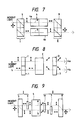
- Fig. 6 shows the fifth embodiment of the present invention.
- the optical isolator unit 4 comprises an optical isolator group 4a disposed on the optical path a and formed by connecting two sets of optical isolator blocks, each of which has the arrangement shown in Fig. 1, in series, and an optical isolator group 4b disposed on the optical path b and formed similar to the optical isolator group 4a, and that the first optical system I includes only the optical member 5 and the second optical system II only the optical member 8.
- the arrangement is made such that the planes of polarization of the first polarizers 1 of the optical isolator groups 4a and 4b make right angles with each other.
- the polarized components of the incident light split by the optical member 5 travel along the optical paths a and b and pass through the optical isolator groups 4a and 4b, respectively.
- the planes of polarization of the first polarizers on the incidence side of the optical isolator groups 4a and 4b coincide individually with those of the polarized components incident thereon, so that the polarized components traversing the two optical isolator groups are again combined by the optical member 8.
- light traveling in a direction opposite to the incident light, although it is split into two polarized components by the optical member 8 is blocked by the optical isolator groups 4a and 4b and fails to reach the optical member 5.
- Fig. 7 shows the sixth embodiment of the present invention.
- This embodiment differs from the fifth embodiment in arrangement that each of the optical members 5 and 8 is constructed by combining two polarizing beam splitters. Since the function and effect of the sixth embodiment are substantially the same as those of the fifth embodiment, the description thereof is omitted. Also, the optical members 5 and 8 can be constructed by each combining the polarizing beam splitters with the reflecting plates.
- the optical isolator groups 4a and 4b constituting the optical isolator unit 4 each include the first polarizer 1, the Faraday rotator 2, and the second polarizer 3, for example, as shown in Fig. 8, the Faraday rotator 2 can be used in common. This enables the optical isolator unit 4 to be compactly designed.
- Fig. 9 illustrates the seventh embodiment of the present invention.
- This embodiment is different from the second embodiment (Fig. 3) in arrangement that the optical isolator unit 4 is constructed by connecting an odd number of optical isolator block sets, each of which has the arrangement shown in Fig. 1, in series, and that the second optical system II includes a polarizing rotator 11 composed of, for example, a half-wave plate, inserted in common with the optical paths a and b between the optical isolator unit 4 and the polarizing rotator 7.
- a polarizing rotator 11 composed of, for example, a half-wave plate
- both the planes of polarization are rotated at 45°, 135°, 225°, or 315° and returned, through the polarizing rotator 11, to a polarizing state before the components are incident on the optical isolator unit 4. Since other functions and effects of the seventh embodiment are the same as those of the second embodiment, a detailed description thereof is omitted.
- Fig. 10 depicts the eighth embodiment of the present invention.
- This embodiment is distinguished from the seventh embodiment by the arrangement that the optical isolator unit 4 is constructed by connecting an even number of optical isolator block sets, each of which has the arrangement shown in Fig. 1, in series, and the two polarized components traveling along the optical paths a and b through the optical isolator unit 4 are rotated 90°, together with the planes of polarization thereof.
- the fundamental function and effect of the eighth embodiment are identical with those of the second embodiment and as such a detailed description thereof is left out.
- Fig. 11 shows the ninth embodiment of the present invention. This embodiment is different from the eighth embodiment in arrangement that an optical member 12, in place of the polarizing rotator 11, similar to the optical member 8 is disposed in common with the optical paths a and b between the polarizing rotator 7 and the optical member 8, and the planes of polarization of the polarized components of the incident light make right angles with those of the emergent light from the optical member 8.
- the substantial function and effect are the same as those of the above-mentioned embodiments, so that a detailed description thereof is omitted. Even though the optical paths a and b are replaced with each other, the function and effect will remain unchanged.
- Fig. 12 shows the tenth embodiment of the present invention.
- This embodiment is different from the ninth embodiment in arrangement that the optical isolator unit 4 is constructed by connecting an even number of optical isolator block sets, each of which has the arrangement shown in Fig. 1, in series, and that in the first optical system I, an optical member 13 similar to the optical member 5 is disposed in common with the optical paths a and b between the optical member 5 and the polarizing rotator 6.
- the substantial function and effect are the same as those of the above-mentioned embodiments, so that a detailed description thereof is omitted. Even though the optical paths a and b are replaced with each other, the function and effect will remain unchanged.
- a light transmission system that cannot previously specify the plane of polarization of the incident light can also be constructed so that the plane of polarization of the incident light coincides with that of the polarizer on the incidence side of the optical isolator unit, thereby allowing an excellent effect of isolation without considering the plane of polarization of the incident light.
Landscapes
- Physics & Mathematics (AREA)
- Nonlinear Science (AREA)
- Engineering & Computer Science (AREA)
- Power Engineering (AREA)
- General Physics & Mathematics (AREA)
- Optics & Photonics (AREA)
Claims (15)
- Polarisationsunabhängiger optischer Richtleiter, umfassend:- eine polarisationsabhängige optische Einwegleitungseinheit (4) mit einem auf der entsprechenden Einfallsseite angebrachten Polarisator (1);- ein erstes, an der Einfallsseite der besagten polarisationsabhängigen Einwegleitungseinheit (4) angeordnetes optisches System (I), um das darin einfallende Licht in zwei linear polarisierte Bestandteile aufzuspalten und die Polarisationsebene einer der beiden besagten linear polarisierten Bestandteile zu drehen, so daß die Polarisationsebenen dieser beiden besagten linear polarisierten Bestandteile mit der Polarisationsebene des besagten Polarisators (1) zusammenfallen, und die beiden besagten linear polarisierten Bestandteile auf die besagte polarisationsabhängige optische Einwegleitungseinheit (4) einfallen zu lassen, wobei die Polarisationsebenen der beiden besagten linear polarisierten Bestandteile mit der Polarisationsebene des besagten Polarisators (1) zusammenfallen; und- ein zweites, an der Austrittsseite der besagten polarisationsabhängigen optischen Einwegleitungseinheit (4) angeordnetes optisches System (II), mit optischen Mitteln, um die beiden linear polarisierten Bestandteile, die aus der besagten polarisationsabhängigen optischen Einwegleitungseinheit (4) austreten, zu einem einzigen Strahl mit demselben Querschnitt wie beim einfallenden Strahl zusammenzusetzen.
- Polarisationsunabhängiger optischer Richtleiter nach Anspruch 1, dadurch gekennzeichnet, daß die besagte polarisationsabhängige optische Einwegleitungseinheit (4) durch Hintereinanderschalten einer geraden Anzahl von Blocksätzen optischer Einwegleiter aufgebaut ist, von denen jeder einen ersten Polarisator (1), eine Faradayschen Rotator (2) und einen zweiten Polarisator (3) besitzt, die in Reihe von der Einfallsseite zur Austrittsseite hin angeordnet sind, wobei das erste optische System (I) ein erstes optisches Glied (5), um das einfallende Licht in die zwei linear polarisierten Bestandteile mit zueinander senkrecht stehenden Polarisationsebenen für zwei optische Pfade (a, b) aufzuspalten, und einen ersten, auf einem der beiden optischen Pfade zwischen dem besagten ersten optischen Glied und besagter polarisationsabhängiger optischer Einwegleitungseinheit (4) angeordneten Polarisationsrotator (6) umfaßt und wobei das zweite optische System (II) einen zweiten, auf dem anderen der beiden optischen Pfade (a, b) auf der Austrittsseite der polarisationsabhängigen optischen Einwegleitungseinheit (4) angeordneten Polarisationsrotator (7) und ein zweites, auf der Austrittsseite des zweiten Polarisationsrotators (7) angeordnetes optisches Glied (8) umfaßt, um die beiden besagten optischen Pfade (a, b) zusammenzusetzen.
- Polarisationsunabhängiger optischer Richtleiter nach Anspruch 2, dadurch gekennzeichnet, daß das erste optische Glied (5) und das zweite optische Glied (8) jeweils eine doppeltbrechende Platte und der erste Polarisationsrotator (6) und der zweite Polarisationsrotator (7) jeweils eine Halbwellen-Platte aufweisen.
- Polarisationsunabhängiger optischer Richtleiter nach Anspruch 1, dadurch gekennzeichnet, daß die polarisationsabhängige optische Einwegleitungseinheit (4) derart ausgebildet ist, daß die Polarisationsebenen der beiden dann einfallenden linear polarisierten Bestandteile im 90°-Winkel zu denen der beiden daraus austretenden linear polarisierten Bestandteile stehen.
- Polarisationsunabhängiger optischer Richtleiter nach Anspruch 1, dadurch gekennzeichnet, daß die polarisationsabhängige optische Einwegleitungseinheit (4) derart ausgebildet ist, daß die Polarisationsebenen der beiden darin einfallenden linear polarisierten Bestandteile mit denen der daraus austretenden zusammenfallen.
- Polarisationsunabhängiger optischer Richtleiter, umfassend:- eine optische Einwegleitungseinheit (4), die aus zwei nebeneinandergeschalteten polarisationsabhängigen Einwegleitungsgruppen (4a, 4b) zusammengesetzt ist, wobei jede der besagten Gruppen jeweils einen auf der entsprechenden Einfallsseite angebrachten Polarisator besitzt;- ein erstes, an der Einfallsseite der besagten Einwegleitungseinheit (4) angeordnetes optisches System (I), um das dann einfallende Licht in zwei linear polarisierte Bestandteile aufzuspalten und die beiden linear polarisierten Bestandteile jeweils auf die beiden polarisationsabhängigen Einwegleitungsgruppen (4a, 4b) einfallen zu lassen, wobei die Polarisationsebene der beiden linear polarisierten Bestandteile jeweils mit den Polarisationsebenen der Polarisatoren zusammenfallen;- ein zweites, an einer Austrittsseite der optischen Einwegleitungseinheit (4) angeordnetes optisches System (II), mit optischen Mitteln, um die beiden linear polarisierten Bestandteile, die aus der besagten polarisationsabhängigen optischen Einwegleitungseinheit (4) austreten, zu einem einzigen Strahl mit demselben Querschnitt wie beim einfallenden Strahl zusammenzufassen.
- Polarisationsunabhängiger optischer Richtleiter nach Anspruch 6, dadurch gekennzeichnet, daß jede der Gruppen polarisationsabhängiger optischer Einwegleitungen (4a, 4b) durch Hintereinanderschalten einer geraden Anzahl von Blocksätzen optischer Einwegleitungen aufgebaut ist, von denen jeder einen ersten Polarisator (1), einen Faradayschen Rotator (2) und einen zweiten Polarisator (3) umfaßt, die in Reihe von der Einfallsseite zur Austrittsseite hin angeordnet sind, wobei das erste optische System (I) und das zweite optische System (II) jeweils zwei miteinander kombinierte Strahlenteiler umfassen.
- Polarisationsunabhängiger optischer Richtleiter nach Anspruch 6, dadurch gekennzeichnet, daß jede der polarisationsabhängigen Gruppen optischer Einwegleitungen (4a, 4b) durch Hintereinanderschalten einer geraden Anzahl von Blocksätzen optischer Einwegleitungen aufgebaut ist, von denen jeder einen ersten Polarisator (1), eine Faradayschen Rotator (2) und einen zweiten Polarisator (3) aufweist, die in Reihe von der Einfallsseite zur Austrittsseite hin angeordnet sind, wobei das erste optische System (I) und das zweite optische System (II) jeweils eine doppeltbrechende Platte aufweisen.
- Polarisationsunabhängiger optischer Richtleiter nach Anspruch 1, dadurch gekennzeichnet, daß die polarisationsabhängige optische Einwegleitungseinheit (4) durch Hintereinanderschalten einer ungeraden Anzahl von Blocksätzen optischer Einwegleitungen aufgebaut ist, von denen jeder einen ersten Polarisator (1), einen Faradayschen Rotator (2) und einen zweiten Polarisator (3) aufweist, die in Reihe von der Einfallsseite zur Austrittsseite hin angeordnet sind, wobei das erste optische System (I) ein erstes optisches Glied (5), um das einfallende Licht in die zwei linear polarisierten Bestandteile mit zueinander senkrecht stehenden Polarisationsebenen für zwei optische Pfade (a, b) aufzuspalten, und einen ersten, auf einem der beiden optischen Pfade (a, b) zwischen dem ersten optischen Glied (5) und besagter polarisationsabhängiger optischer Einwegleitungseinheit (4) angeordneten Polarisationsrotator (6) umfaßt und das zweite optische System (II) einen zweiten, auf beiden besagten optischen Pfaden (a, b) zum Zweck der gemeinsamen Benutzung auf der Austrittsseite der optischen Einwegleitungseinheit (4) angeordneten Polarisationsrotator (11), einen dritten, auf einem der beiden optischen Pfade (a, b) auf der Austrittsseite des besagten zweiten Polarisationsrotators (11) angeordneten Polarisationsrotator (7) und ein zweites, auf der Austrittsseite des dritten Polarisationsrotators (7) angeordnetes optisches Glied (8) umfaßt, um die beiden optischen Pfade (a, b) zusammenzusetzen.
- Polarisationsunabhängiger optischer Richtleiter nach Anspruch 1, dadurch gekennzeichnet, daß die polarisationsabhängige optische Einwegleitungseinheit (4) durch Hintereinanderschalten einer geraden Anzahl von Blocksätzen optischer Einwegleitungen ausgebildet ist, von denen jeder einen ersten Polarisator (1), eine Faradayschen Rotator (2) und einen zweiten Polarisator (3) aufweist, die in Reihe von der Einfallsseite zur Austrittsseite hin angeordnet sind, wobei das erste optische System (I) ein erstes optisches Glied (5), um das einfallende Licht in die zwei linear polarisierten Bestandteile mit zueinander senkrecht stehenden Polarisationsebenen für zwei optische Pfade (a, b) aufzuspalten, und einen ersten, auf einem der beiden besagten optischen Pfade (a, b) zwischen dem besagten ersten optischen Glied (5) und besagter optischer Einwegleitungseinheit (4) angeordneten Polarisationsrotator (6) umfaßt und das zweite optische System (II) einen zweiten, auf beiden optischen Pfaden (a, b) zum Zweck der gemeinsamen Benutzung auf der Austrittsseite der polarisationsabhängigen optischen Einwegleitungseinheit (4) angeordneten Polarisationsrotator (11), einen dritten, auf einem der beiden optischen Pfade (a, b) auf der Austrittsseite des zweiten Polarisationsrotators (11) angeordneten Polarisationsrotator (7) und ein zweites, auf der Austrittsseite des dritten Polarisationsrotators (7) angeordnetes optisches Glied umfaßt, um die beiden optischen Pfade (a, b) zusammenzusetzen.
- Polarisationsunabhängiger optischer Richtleiter nach den Ansprüchen 9 oder 10, dadurch gekennzeichnet, daß die ersten und zweiten optischen Glieder (5, 8) jeweils eine doppeltbrechende Platte und die ersten, zweiten und dritten Polarisationsrotatoren (6, 11, 7) jeweils eine Halbwellen-Platte aufweisen.
- Polarisationsunabhängiger optischer Richtleiter nach Anspruch 1, dadurch gekennzeichnet, daß die polarisationsabhängige optische Einwegleitungseinheit (4) durch Hintereinanderschalten einer ungeraden Anzahl von Blocksätzen optischer Einwegleitungen ausgebildet ist, von denen jeder einen ersten Polarisator (1), einen Faradayschen Rotator (2) und einen zweiten Polarisator (3) aufweist, die in Reihe von der Einfallsseite zur Austrittsseite hin angeordnet sind, wobei das erste optische System (I) ein erstes optisches Glied (5), um das einfallende Licht in die zwei linear polarisierten Bestandteile mit zueinander senkrecht stehenden Polarisationsebenen für zwei optische Pfade (a, b) aufzuspalten, und einen ersten, auf einem der beiden optischen Pfade zwischen dem ersten optischen Glied (5) und der polarisationsabhängigen optischen Einwegleitungseinheit (4) angeordneten Polarisationsrotator (6) umfaßt, wobei das zweite optische System (II) einen zweiten, auf einem der beiden optischen Pfade auf der Austrittsseite der polarisationsabhängigen optischen Einwegleitungseinheit (4) angeordneten Polarisationsrotator (7) und zweite und dritte, auf beiden optischen Pfaden (a, b) zum Zweck der gemeinsamen Benutzung auf der Austrittsseite des zweiten Polarisationsrotators (7) angeordnete optische Glieder (12, 8) umfaßt, um die beiden optischen Pfade (a, b) zusammenzusetzen.
- Polarisatonsunabhängiger optischer Richtleiter nach Anspruch 12, dadurch gekennzeichnet, daß die ersten, zweiten und dritten optischen Glieder (5, 12, 8) jeweils eine doppeltbrechende Platte und die ersten und zweiten Polarisationsrotatoren (6, 7) jeweils eine Halbwellen-Platte aufweisen.
- Polarisationsunabhängiger optischer Richtleiter nach Anspruch 2, dadurch gekennzeichnet, daß die ersten und zweiten optischen Systeme (I, II) jeweils ein Paar im räumlichen Abstand voneinander angeordneter doppeltbrechender Platten und die ersten und zweiten Polarisationsrotatoren (6, 7) jeweils eine Halbwellen-Platte aufweisen.
- Polarisationsunabhängiger optischer Richtleiter nach Anspruch 6, dadurch gekennzeichnet, daß die ersten und zweiten optischen Systeme (I, II) jeweils eine Kombination von Polarisations-Strahlenteilem mit reflektierenden Platten aufweisen.
Applications Claiming Priority (14)
| Application Number | Priority Date | Filing Date | Title |
|---|---|---|---|
| JP41227890A JP2904442B2 (ja) | 1990-12-20 | 1990-12-20 | 光アイソレータ |
| JP412278/90 | 1990-12-20 | ||
| JP4302791A JPH04260019A (ja) | 1991-02-15 | 1991-02-15 | 光アイソレータ |
| JP43027/91 | 1991-02-15 | ||
| JP9526791A JPH04324417A (ja) | 1991-04-25 | 1991-04-25 | 光アイソレータ |
| JP95266/91 | 1991-04-25 | ||
| JP9526691A JPH04324416A (ja) | 1991-04-25 | 1991-04-25 | 光アイソレータ |
| JP95267/91 | 1991-04-25 | ||
| JP13426591A JPH04359220A (ja) | 1991-06-05 | 1991-06-05 | 光アイソレータ |
| JP134265/91 | 1991-06-05 | ||
| JP13664791A JPH04360118A (ja) | 1991-06-07 | 1991-06-07 | 光アイソレータ |
| JP136647/91 | 1991-06-07 | ||
| JP13664891A JPH04360119A (ja) | 1991-06-07 | 1991-06-07 | 光アイソレータ |
| JP136648/91 | 1991-06-07 |
Publications (2)
| Publication Number | Publication Date |
|---|---|
| EP0492437A1 EP0492437A1 (de) | 1992-07-01 |
| EP0492437B1 true EP0492437B1 (de) | 1997-03-05 |
Family
ID=27564558
Family Applications (1)
| Application Number | Title | Priority Date | Filing Date |
|---|---|---|---|
| EP19910121786 Expired - Lifetime EP0492437B1 (de) | 1990-12-20 | 1991-12-19 | Polarisationsunabhängiger optischer Isolator |
Country Status (3)
| Country | Link |
|---|---|
| EP (1) | EP0492437B1 (de) |
| CA (1) | CA2058036C (de) |
| DE (1) | DE69124955T2 (de) |
Families Citing this family (3)
| Publication number | Priority date | Publication date | Assignee | Title |
|---|---|---|---|---|
| JP2775547B2 (ja) * | 1992-02-17 | 1998-07-16 | 秩父小野田株式会社 | 光アイソレータ |
| US9268159B2 (en) * | 2012-11-09 | 2016-02-23 | Electro-Optics Technology, Inc. | Low focal shift kW class optical isolator |
| US10718963B1 (en) | 2016-11-16 | 2020-07-21 | Electro-Optics Technology, Inc. | High power faraday isolators and rotators using potassium terbium fluoride crystals |
Family Cites Families (2)
| Publication number | Priority date | Publication date | Assignee | Title |
|---|---|---|---|---|
| JPS55121215U (de) * | 1979-02-21 | 1980-08-28 | ||
| DD152212A1 (de) * | 1980-07-15 | 1981-11-18 | Volkmar Norkus | Optisches system zur umwandlung der polarisation von licht |
-
1991
- 1991-12-18 CA CA 2058036 patent/CA2058036C/en not_active Expired - Fee Related
- 1991-12-19 DE DE1991624955 patent/DE69124955T2/de not_active Expired - Fee Related
- 1991-12-19 EP EP19910121786 patent/EP0492437B1/de not_active Expired - Lifetime
Also Published As
| Publication number | Publication date |
|---|---|
| CA2058036A1 (en) | 1992-06-21 |
| CA2058036C (en) | 1997-10-28 |
| DE69124955D1 (de) | 1997-04-10 |
| EP0492437A1 (de) | 1992-07-01 |
| DE69124955T2 (de) | 1997-11-27 |
Similar Documents
| Publication | Publication Date | Title |
|---|---|---|
| US5267078A (en) | Optical isolator | |
| US5446578A (en) | Polarization preserving optical isolator | |
| US5574596A (en) | Optical circulator | |
| US5930038A (en) | Optical isolator with polarization dispersion and differential transverse deflection correction | |
| US6236506B1 (en) | Reflection-type optical circulation utilizing a lens and birefringent plates | |
| EP0552783B1 (de) | Optischer Isolator | |
| EP0840902B1 (de) | Optischer zirkulator | |
| US20080199125A1 (en) | In-line optical isolator | |
| JP2943436B2 (ja) | 半導体レーザモジュール | |
| US6091543A (en) | Apparatus for providing non-reciprocal termination of parallel like polarization modes | |
| EP0492437B1 (de) | Polarisationsunabhängiger optischer Isolator | |
| US6865024B1 (en) | Multi-functional optical device utilizing multiple polarization beam splitters and non-linear interferometers | |
| JP3161885B2 (ja) | 光アイソレーター | |
| CA2328564C (en) | Multi-stage optical isolator | |
| JP3317999B2 (ja) | 光アイソレータ | |
| US6853488B1 (en) | Reflection-type optical circulator utilizing a lens and birefringent plates | |
| US6762879B1 (en) | Method and system for providing an optical circulator | |
| JPH07191279A (ja) | 光学アイソレータ | |
| JP3569873B2 (ja) | 偏光無依存型光アイソレータ | |
| JPH03290612A (ja) | 光アイソレータ装置 | |
| JPS6111683Y2 (de) | ||
| JP2002228984A (ja) | 光サーキュレータ | |
| JP3388377B2 (ja) | 偏光無依存型光サーキュレータ | |
| RU2082190C1 (ru) | Оптический изолятор | |
| JP2002031780A (ja) | 光サーキュレータ及び光スイッチ |
Legal Events
| Date | Code | Title | Description |
|---|---|---|---|
| PUAI | Public reference made under article 153(3) epc to a published international application that has entered the european phase |
Free format text: ORIGINAL CODE: 0009012 |
|
| AK | Designated contracting states |
Kind code of ref document: A1 Designated state(s): DE FR GB |
|
| RIN1 | Information on inventor provided before grant (corrected) |
Inventor name: NAKAJIMA, KAZUHIRO Inventor name: NUMAJIRI, YASUO Inventor name: SHIRAISHI, KAZUO |
|
| RIN1 | Information on inventor provided before grant (corrected) |
Inventor name: NUMAJIRI, YASUO Inventor name: NAKAJIMA, KAZUHIRO Inventor name: SHIRAISHI, KAZUO |
|
| RIN1 | Information on inventor provided before grant (corrected) |
Inventor name: NUMAJIRI, YASUO Inventor name: NAKAJIMA, KAZUHIRO Inventor name: SHIRAISHI, KAZUO |
|
| 17P | Request for examination filed |
Effective date: 19921229 |
|
| 17Q | First examination report despatched |
Effective date: 19940711 |
|
| GRAG | Despatch of communication of intention to grant |
Free format text: ORIGINAL CODE: EPIDOS AGRA |
|
| GRAH | Despatch of communication of intention to grant a patent |
Free format text: ORIGINAL CODE: EPIDOS IGRA |
|
| GRAH | Despatch of communication of intention to grant a patent |
Free format text: ORIGINAL CODE: EPIDOS IGRA |
|
| GRAA | (expected) grant |
Free format text: ORIGINAL CODE: 0009210 |
|
| AK | Designated contracting states |
Kind code of ref document: B1 Designated state(s): DE FR GB |
|
| REF | Corresponds to: |
Ref document number: 69124955 Country of ref document: DE Date of ref document: 19970410 |
|
| ET | Fr: translation filed | ||
| PLBE | No opposition filed within time limit |
Free format text: ORIGINAL CODE: 0009261 |
|
| STAA | Information on the status of an ep patent application or granted ep patent |
Free format text: STATUS: NO OPPOSITION FILED WITHIN TIME LIMIT |
|
| 26N | No opposition filed | ||
| REG | Reference to a national code |
Ref country code: GB Ref legal event code: IF02 |
|
| PGFP | Annual fee paid to national office [announced via postgrant information from national office to epo] |
Ref country code: FR Payment date: 20021210 Year of fee payment: 12 |
|
| PGFP | Annual fee paid to national office [announced via postgrant information from national office to epo] |
Ref country code: GB Payment date: 20021218 Year of fee payment: 12 |
|
| PGFP | Annual fee paid to national office [announced via postgrant information from national office to epo] |
Ref country code: DE Payment date: 20021219 Year of fee payment: 12 |
|
| PG25 | Lapsed in a contracting state [announced via postgrant information from national office to epo] |
Ref country code: GB Free format text: LAPSE BECAUSE OF NON-PAYMENT OF DUE FEES Effective date: 20031219 |
|
| PG25 | Lapsed in a contracting state [announced via postgrant information from national office to epo] |
Ref country code: DE Free format text: LAPSE BECAUSE OF NON-PAYMENT OF DUE FEES Effective date: 20040701 |
|
| GBPC | Gb: european patent ceased through non-payment of renewal fee |
Effective date: 20031219 |
|
| PG25 | Lapsed in a contracting state [announced via postgrant information from national office to epo] |
Ref country code: FR Free format text: LAPSE BECAUSE OF NON-PAYMENT OF DUE FEES Effective date: 20040831 |
|
| REG | Reference to a national code |
Ref country code: FR Ref legal event code: ST |