EP0492635A1 - Elektro-Myograph mit Datenübertragung ohne Metalleiter - Google Patents
Elektro-Myograph mit Datenübertragung ohne Metalleiter Download PDFInfo
- Publication number
- EP0492635A1 EP0492635A1 EP91122269A EP91122269A EP0492635A1 EP 0492635 A1 EP0492635 A1 EP 0492635A1 EP 91122269 A EP91122269 A EP 91122269A EP 91122269 A EP91122269 A EP 91122269A EP 0492635 A1 EP0492635 A1 EP 0492635A1
- Authority
- EP
- European Patent Office
- Prior art keywords
- electromyograph
- filter
- signals
- electrodes
- apt
- Prior art date
- Legal status (The legal status is an assumption and is not a legal conclusion. Google has not performed a legal analysis and makes no representation as to the accuracy of the status listed.)
- Granted
Links
Images



Classifications
-
- A—HUMAN NECESSITIES
- A61—MEDICAL OR VETERINARY SCIENCE; HYGIENE
- A61B—DIAGNOSIS; SURGERY; IDENTIFICATION
- A61B5/00—Measuring for diagnostic purposes; Identification of persons
- A61B5/24—Detecting, measuring or recording bioelectric or biomagnetic signals of the body or parts thereof
- A61B5/30—Input circuits therefor
- A61B5/307—Input circuits therefor specially adapted for particular uses
- A61B5/313—Input circuits therefor specially adapted for particular uses for electromyography [EMG]
-
- A—HUMAN NECESSITIES
- A61—MEDICAL OR VETERINARY SCIENCE; HYGIENE
- A61B—DIAGNOSIS; SURGERY; IDENTIFICATION
- A61B5/00—Measuring for diagnostic purposes; Identification of persons
- A61B5/24—Detecting, measuring or recording bioelectric or biomagnetic signals of the body or parts thereof
- A61B5/30—Input circuits therefor
- A61B5/305—Common mode rejection
-
- A—HUMAN NECESSITIES
- A61—MEDICAL OR VETERINARY SCIENCE; HYGIENE
- A61B—DIAGNOSIS; SURGERY; IDENTIFICATION
- A61B5/00—Measuring for diagnostic purposes; Identification of persons
- A61B5/24—Detecting, measuring or recording bioelectric or biomagnetic signals of the body or parts thereof
- A61B5/316—Modalities, i.e. specific diagnostic methods
- A61B5/389—Electromyography [EMG]
Definitions
- the present invention concerns an electromyograph wherein the data detected on the patient is transmitted to the receiving unit without the use of metallic conductors, for instance by optical means or by radio communication.
- the electromyograph is a medical instrument used to detect the electric muscular activity by means of surface electrodes applied on the patient's skin, or by means of needle electrodes inserted into the patient's muscle in the body parts of which the muscular functionality needs to be studied. Said instrument is used more and more frequently to study the physiology of the muscular apparatus in healthy subjects and to thus acquire a list of data for use in the study and treatment of muscular pathologies and, in particular, in therapies to recover the muscular functionality of previously injured parts.
- the electromyograph of known technique uses the same technology of the already known and tested instruments for detecting the electric activity of other organs of the human body, as for instance the electroencephalograph or the electrocardiograph, and it hence consists of a table instrument from which depart a plurality of electric cables which are connected to electrodes suitably fixed to the patient's body.
- This technique which has given and still gives satisfactory results in the study of the heart and brain functions, has instead not given equally satisfactory results in the study of the muscular functions. This depends on a variety of factors, all however substantially leading to the fact that the muscular functions have also to be taken while the muscle is contracting and thus in a dynamic condition, as opposed to the previously cited functions which can be taken in a fully static condition.
- a second serious problem concerns the patient's protection against electric shocks; the patient is in fact physically connected to the power mains through the electromyograph and the cables connecting the electrodes, i.e. through metallic conductors, his insulation being guaranteed only by the presence of suitable electronic insulating devices allowing to transmit the electric signals but not the electric current, for instance by interrupting the metallic conductors through electric optical devices.
- Such insulating devices may however be subject to failures or damages, whereby there is always the danger of current leakages between the main circuit and the electric circuit detecting the signal and contacting the patient.
- the laws providing for safety measures on such instruments are hence becoming stricter and stricter, thereby involving high construction costs, especially when the instruments have also to be used - as in the present case - in dynamic conditions, which objectively increase the possibilities of accidental damages.
- a third drawback is tied to the fact that the electric activity at muscular level is very feeble and thus requires to be considerably amplified so as to be perceived by the instruments.
- the electric interferences which may overlap the signals coming from the muscular activity, and consequently modify them, are therefore particularly troublesome; these no doubt include the interferences generated by the movement of the electric cables connecting the electrodes to the instrument within the electromagnetic fields existing in the environment, and those deriving from the impedance variations of the electrode/patient interface.
- the object of the present invention is to thus supply an electromyograph apt to overcome all the above mentioned drawbacks, allowing to keep the patient constantly and perfectly insulated from the main electric circuit, allowing him a wide freedom of movement, and finally allowing to eliminate the electric interferences determined by the movement of the metallic cables transmitting the electric signals.
- said object is reached by means of an electromyograph, of the type in which the electric muscular activity is detected by means of electrodes applied on the skin or inserted into the patient's muscle, characterized in that it comprises a portable unit applied on the patient and electrically connected to said electrodes, apt to pick up the analog signals issued therefrom, to convert them into digital signals and to formatte them in serial form; transmission means, comprising no metallic conductors, apt to transmit said digital signals formatted in serial form; and a fixed unit connected to said transmission means, apt to receive said formatted and serialized digital signals, and to decode and convert them into analog signals.
- said transmission means consist of at least one optical fiber cable.
- said transmission means consist of radio communication means.
- the electromyograph of the present invention faces in an innovating way the problem of detecting the electric muscular activity, thanks to the fact that it substantially comprises two distinct units, reciprocally connected by transmission means comprising no metallic conductors, apt to transmit serialized digital signals; said transmission means consist of optical means or, alternatively, of radio communication means.
- a portable unit light and of small dimensions, is applied on the patient during the test, for instance by simply inserting it into a pocket of his clothes, or by fixing it with belts or other systems to the patient's body if he is wearing no clothes.
- Detection electrodes are electrically connected to said unit and fixed, thanks to their adhesive surface, into the body parts being tested. Since the signal of the muscular activity is taken in a differential way, each electrode actually consists of a pair of electrodes, whose differential signal is preamplified by a subminiature preamplifier positioned close to the end of the electrode cable, preferably at a distance of not more than 20 mm from the pair of electrodes, so as to render completely negligible the electric interferences determined by the movement of the cables.
- the portable unit picks up the signals issued from the electrodes and filters them, then provides for their A/D conversion and finally formattes them in serial form. This allows to use the transmission means without metallic conductors of the present invention for transmitting the digital serialized signals to a fixed remote unit in an easy and interference-free way.
- Said fixed remote unit decodes the digital serialized signals received from the portable unit through said transmission means, then provides for the D/A reconversion thereof, thereafter amplifies and filters them, and finally makes avialable to the operator the processed signals.
- the fundamental parameters of the signals, for each detection channel, can be regulated by the operator.
- a digital output is provided, as an alternative to the analog output, in the event of the signals having to be further processed by a data processor.
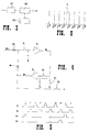
- Fig. 1 shows the portable unit 1 of the electromyograph, carrying on the front panelboard ten connectors, and precisely the connectors A1-A8 designed to connect an equal number of detection electrodes, and the connectors L and R designed to connect the stride-phase channels of the left and, respectively, right foot.
- the movements of the foot are registered through the stride-phase channels, by reading the signals issued from three piezo-resistive sensors positioned respectively under the toe, the centre and the heel of each foot.
- Each stride-phase channel hence actually comprises three independent sub-channels.
- the portable unit 1 is operated by means of the switch 2 and its working condition is signalled by the warning light 3.
- the power required to operate the unit 1 is supplied by a 9 V alkaline battery 10 housed inside said unit.
- Two hollow and externally threaded connectors 4 and 5 are finally provided for connection to the fixed unit, into which connectors there are inserted respective optical fiber cables RX and TX which are then fixed in position by tightening the ring nuts 4g and 5g.
- the connectors 4 and 5 may be different from these disclosed above, depending from the optical fiber cable used; for instance fast plug-in connectors are preferred in many applications.
- the block diagram of fig. 2 shows the circuitry of the portable unit 1.
- the electric signal issued from the detection electrodes is sent, through the connectors A1-A8, to an equal number of corresponding identical blocks B1-B8, of which only the block B1 is illustrated in further detail for simplicity's sake.
- the signal issued from the preamplifier of the electrode connected to the connector A1 is thus first of all amplified in B/A, realizing a common mode rejection ratio (CMRR) exceeding 100 db.
- CMRR common mode rejection ratio
- the differential gain of this stage depends on the type of electrode which has been connected, and can be varied by moving a suitable jumper provided in the connector of said electrode or on the printed circuit board of the same stage B/A..
- One of the electrodes of the electromyograph according to the present invention comprises, in addition to the pair of detection electrodes, also a third ground electrode apt to supply a reference voltage for all the amplifiers.
- the signal thus amplified passes through an anti-aliasing filter B/F with a cutoff frequency of 800 Hz (at -3 db) and an attenuation slope of 9 db/octave.
- Said filter in order to guarantee a linear in-phase response, is realized with a discrete time oversampling technique, better described hereinafter.
- An amplifying and voltage limiting stage B/L finally sends the signal to an analog/digital converter 6 which, besides converting the signals into digital form, also formattes them in serial form on 10 bit in 200 ⁇ s.
- the digital signals, thus serialized, are finally transmitted onto the optical fiber cable TX through a transmitting device 7 which receives the signals from the converter 6.
- the optical transmission is of the asynchronous type with non-standard protocol.
- the portable unit 1 also comprises - as said above - the connectors L and R, which receive the stride-phase signals issued from six piezo-resistive sensors fixed into suitable points, three for each foot of the patient.
- the signals issued from said piezo-resistive sensors are first sent to an input match stage B/I, where they are compared with a fixed threshold to give an OFF/ON output, and then to a digital/analog converter B/C which generates voltages of variable amplitude according to the state of the piezo-resistive sensors.
- These analog voltages are sent to the analog/digital converter 6 and are transmitted, similarly to the electromyographic signals, onto a single channel reserved for them, which hence forms the ninth channel of the electromyograph described herein.
- the portable unit 1 finally comprises a receiving device 8, connected to a second optical fiber cable RX, through which it is possible to control, directly from the fixed unit, the operation of a supply block 9.
- a receiving device 8 connected to a second optical fiber cable RX, through which it is possible to control, directly from the fixed unit, the operation of a supply block 9.
- the supply block 9 generates the voltages required for the working of the different circuits and for their stabilization, using up the electric energy received from the battery 10.
- the anti-aliasing filter B/F - in order to guarantee a linear in-phase response - operates according to a discrete time oversampling technique, which is now illustrated in detail with reference to figs. 3 to 7.
- Said filter is referred to as discrete time filter in that it operates with a discrete series of measurements taken - as already seen - on an analog signal.
- the circuitry of one of the anti-aliasing filters B/F is illustrated in fig. 3, where it can be seen how the input signal is first filtered in a low-pass filter 11, and then in a moving average filter 12 monitored by a monitoring circuit 13.
- the filter 11 is an RC filter of the first order, which cuts off all the signal components having a frequency higher than FS/2, where FS is the frequency of the first sampling (or oversampling, taken upstream of the filter 12) equal to 40,000 Hz in the illustrated example, in turn equal to eight times the actual sampling frequency FC (downstream of the filter 12) equal to 5,000 Hz.
- FS is the frequency of the first sampling (or oversampling, taken upstream of the filter 12) equal to 40,000 Hz in the illustrated example, in turn equal to eight times the actual sampling frequency FC (downstream of the filter 12) equal to 5,000 Hz.
- FC downstream of the filter 12
- the cycle starts at time 1 with the closing of the switch I3 which determines the zerosetting of V2 connecting the circuit to earth.
- V2 V in(3) + V in(1) .
- V2 represents the summing up of the input voltage values at times 1 and 3.
- the switch I4 is closed, so that the voltage V2 is sent to the output.
- a new cycle is started, with the closing of I3 and the consequent zerosetting of V2.
- the spectral response of the moving average filter 12 is: and is illustrated, vs. time and vs. frequency, in figs. 6 and 7 respectively.
- Fig. 7 reports, as well as the response of filter 12, also the response of the low-pass filter 11.
- the overall response of the discrete time filter B/F is given by the product of the two functions illustrated in fig. 7.
- the heretofore described portable unit 1 is of extremely limited dimensions and weight; in the embodiment shown, it can in fact be housed into a container of about 15x9x3 cm and it weighs approx. 400 g. Said unit can thus be applied on the patient with extreme easiness and without in the least disturbing or hampering his movements.
- the fixed unit of the electromyograph according to the present invention is preferably mounted in a 48.26 cm (19'') frame for modular cards, apt to receive twelve cards Europe format (100x160 mm).
- the block diagram of this unit is illustrated in fig. 8.
- the signals processed by the portable unit 1 and transmitted by means of the optical fiber cable TX are received into a receiving-transmitting card N.
- the card N has the double function of converting again into electric signals the optical signals issued from the cable TX and of generating the stand-by optical signal which is transmitted to the receiving device 8 of the portable unit 1 through the cable RX.
- the digital electric signals issued from the card N are sent, through a single interconnection card T, to a decoding and D/A conversion card O which receives the data sent from the card N in serial form.
- Each digital string of data contains the sampled values of the eight analog channels, the stride-phase information, the state of charge of the battery and some synchronizing pulses.
- the card O detects these synchronizing pulses and utilizes the same to carry out the separation of the channels and of the stride-phase information, as well as the 10 bit D/A conversion.
- the signals relative to the eight electromyographic channels are all made available in Oc to each of the channel filter cards P1-P8, always through the same interconnection card T, so as to be selectively filtered therein, as better explained hereinafter.
- the stride-phase information on the condition of the six piezo-resistive sensors is instead made directly available on the rear panelboard S of the fixed unit, both in digital form (outputs Obd) and in analog form (outputs Oba).
- Each filter card P1-P8 can filter only the signal of one myographic channel, in a way apt to be independently programmed by the operator by means of controls provided on the front panelboard of the fixed unit. Once the filtering operation has been carried out, said signals are sent through the interconnection card T to an output card Q, and are made available for reading through the connectors Q1-Q8 of the BNC type, equally provided on the front panelboard of the fixed unit of the electromyograph according to the present invention.
- a digital output is provided for the signals which have been decoded in the card O but not yet subjected to digital/analog conversion, and said output is made available on the rear panelboard S of the fixed unit by means of a "D" type 37-pole female cup connector.
- This output is provided to allow direct processing, by means of an electronic processor, of the detected myographic signals.
- the interconnection circuitry of the card T is studied so that the position of the single cards in the frame is totally free.
- the instrument is thus able to work with a reduced number of cards P, if this should be desirable; since, however, the clock function required for the operation of the cards P is contained in the card P1 (output P1c), it is indispensable for at least this latter to be constantly inserted into the frame.
- the fixed unit is completed by a supply and switching block R, apt to feed said unit, to generate the stabilized voltages required for the operation of the single cards, and to start the stand-by function of the portable unit 1 at the end of the time period in which said unit is allowed to acquire the data.
- Said time period can be preset at will by the operator or it can be manually started and terminated by the same through appropriate controls provided on the front part of the instrument.
- the circuit diagram of the card N is illustrated in further detail in fig. 9.
- the portable unit 1 When the portable unit 1 is operated by means of the switch 2, it can find itself - as said - in two different operating conditions, of data acquisition and respectively of stand-by, in order to optimize consumption of the battery 10 and thus increase its autonomy.
- the changeover from one to the other of these conditions is controlled by the FLIP/FLOP circuit 14 which is set by the push button 15 or by a remote signal sent to the input 16.
- the condition of data acquisition is visually signalled by the lighting of the warning light 17.
- the FLIP/FLOP 14 is reset - at the end of the operation of data acquisition on the patient - by a timing circuit 18, at the end of the time preset by means of the selector 19, or else by means of a remote signal sent to the input 20.
- the selector 19 activates the function of manual control of the data acquisition time and it signals said condition by lighting the warning light 21.
- the push button 15 takes up a bistable mode and the FLIP/FLOP 14 can thus be set and reset by successively pressing the same button 15.
- the card N obviously comprises a receiving device 22, for receipt of the optical signals transmitted by the optical fiber cable TX and for their conversion into digital electric signals, which are sent to the output 24, and a transmitting device 23, connected to the optical cable RX, for the conversion into optical signals of the electric signals sent from the FLIP/FLOP 14. These last signals are made available also to an output 25, for the synchronizing of external devices.
- Fig. 10 illustrates in further detail the circuit diagram of one of the filter cards P1-P8.
- the signals from all the eight electromyographic channels are made available on all the cards P, one for each of the eight inputs PE, only one of which is connected to the circuit of the card P by means of a jumper 26. It is hence possible to assign to each card the channel having to be filtered therein by simply inserting the jumper 26 in the corresponding position, whereby the same channel can for example be filtered in more than one card, in different ways.
- the electromyographic signal preselected for filtering is first of all sent to a high-pass filter 27, selectable at 1/5/10 Hz, and then to an amplifying stage 28 with selectable gain at 1/2/5/10.
- An ON/OFF device 29 allows to activate or to exclude the function of a notch filter 30, centred at 50 or 60 Hz for rejecting the interferences from the power mains.
- the signal then passes onto a low-pass filter 31, which can be selected at 600/400/200 Hz, or totally deactivated in the event one should wish the signal not to be filtered on the high frequencies.
- An output selector 32 allows to choose between direct output 32a, rectified output 32b, and rectified and integrated output with three different time constants 32c.
- the signal thus processed is finally sent to eight outputs PU, selectable similarly to the inputs PE by means of a jumper 33.
- One of the cards P, and precisely the card P1 also carries a clock oscillator circuit 34, required for the operation of the filters. Said card, as said above, must therefore always be present in the instrument.
- the transmission means apt to transmit the digital data between the portable unit and the fixed unit consist - as specified heretofore - of radio communication means.
- the transmitting-receiving devices 7 and 8 of the portable unit, and the receiving-transmitting devices 22 and 23 of the card N of the fixed unit are replaced by equivalent radioreceiving-radiotransmitting devices, the construction technology of which is fully known and need not therefore be further illustrated.
- the remaining part of the instrument is perfectly identical to that described heretofore.
Landscapes
- Life Sciences & Earth Sciences (AREA)
- Health & Medical Sciences (AREA)
- Surgery (AREA)
- Animal Behavior & Ethology (AREA)
- Pathology (AREA)
- Engineering & Computer Science (AREA)
- Biomedical Technology (AREA)
- Heart & Thoracic Surgery (AREA)
- Medical Informatics (AREA)
- Molecular Biology (AREA)
- Physics & Mathematics (AREA)
- Biophysics (AREA)
- General Health & Medical Sciences (AREA)
- Public Health (AREA)
- Veterinary Medicine (AREA)
- Measurement And Recording Of Electrical Phenomena And Electrical Characteristics Of The Living Body (AREA)
- Arrangements For Transmission Of Measured Signals (AREA)
- Electrotherapy Devices (AREA)
- Measuring Instrument Details And Bridges, And Automatic Balancing Devices (AREA)
- Measuring And Recording Apparatus For Diagnosis (AREA)
- Communication Cables (AREA)
Applications Claiming Priority (2)
| Application Number | Priority Date | Filing Date | Title |
|---|---|---|---|
| IT02256690A IT1246752B (it) | 1990-12-28 | 1990-12-28 | Elettromiografo a trasmissione ottica dei dati. |
| IT2256690 | 1990-12-28 |
Publications (2)
| Publication Number | Publication Date |
|---|---|
| EP0492635A1 true EP0492635A1 (de) | 1992-07-01 |
| EP0492635B1 EP0492635B1 (de) | 1997-03-19 |
Family
ID=11197911
Family Applications (1)
| Application Number | Title | Priority Date | Filing Date |
|---|---|---|---|
| EP91122269A Expired - Lifetime EP0492635B1 (de) | 1990-12-28 | 1991-12-27 | Elektro-Myograph mit Datenübertragung ohne Metalleiter |
Country Status (10)
| Country | Link |
|---|---|
| US (1) | US5233999A (de) |
| EP (1) | EP0492635B1 (de) |
| JP (1) | JP3236047B2 (de) |
| AT (1) | ATE150276T1 (de) |
| CA (1) | CA2058577C (de) |
| DE (1) | DE69125258T2 (de) |
| DK (1) | DK0492635T3 (de) |
| ES (1) | ES2101714T3 (de) |
| GR (1) | GR3023805T3 (de) |
| IT (1) | IT1246752B (de) |
Cited By (2)
| Publication number | Priority date | Publication date | Assignee | Title |
|---|---|---|---|---|
| EP1004267A3 (de) * | 1998-11-26 | 2001-04-11 | Valerio Cigaina | Implantatvorrichtung für innere-äussere elektromyografische Aufzeichnung insbesondere für die invivo Untersuchung von elektromotorischer Aktivität des Verdauungssystems |
| WO2002080768A1 (de) * | 2001-04-05 | 2002-10-17 | Eldith Gmbh | Erfassung von signalen biologischen ursprungs |
Families Citing this family (14)
| Publication number | Priority date | Publication date | Assignee | Title |
|---|---|---|---|---|
| US5341813A (en) * | 1993-03-19 | 1994-08-30 | Liberty Mutual Insurance Co. | Prosthetics electrode array diagnostic system |
| US5579781A (en) * | 1994-10-13 | 1996-12-03 | Cooke; Thomas H. | Wireless transmitter for needle electrodes as used in electromyography |
| US5711307A (en) * | 1995-04-13 | 1998-01-27 | Liberty Mutual Insurance Company | Method and apparatus for detecting myoelectric activity from the surface of the skin |
| AU2007203300B8 (en) * | 2001-04-05 | 2011-08-18 | Neuroconn Gmbh | Arrangement and Method for Recording Signals of Biological Origin |
| JP3775258B2 (ja) * | 2001-07-31 | 2006-05-17 | 株式会社デンソー | フィルタリング方法及びフィルタ機能を有するa/d変換装置 |
| US20050261559A1 (en) * | 2004-05-18 | 2005-11-24 | Mumford John R | Wireless physiological monitoring system |
| JP4738159B2 (ja) * | 2005-12-12 | 2011-08-03 | 株式会社Ihi | 筋電位計測用電極装置 |
| US8298216B2 (en) * | 2007-11-14 | 2012-10-30 | Myoscience, Inc. | Pain management using cryogenic remodeling |
| CN101822540A (zh) * | 2010-04-28 | 2010-09-08 | 上海诺诚电气有限公司 | 肌电放大器及采样肌电信号的方法 |
| WO2013109815A1 (en) * | 2012-01-19 | 2013-07-25 | Volcano Corporation | Interface devices, systems, and methods for use with intravascular pressure monitoring devices |
| US20150366504A1 (en) * | 2014-06-20 | 2015-12-24 | Medibotics Llc | Electromyographic Clothing |
| JP6532857B2 (ja) | 2013-03-15 | 2019-06-19 | ボルケーノ コーポレイション | 脈管内圧モニタ装置と共に使用するためのインターフェイス装置、システム、及び方法 |
| US9585583B1 (en) | 2014-03-04 | 2017-03-07 | Mortara Instrument, Inc. | Myogram determination from ECG signal |
| JP7015602B1 (ja) * | 2021-11-04 | 2022-02-14 | 株式会社Arblet | 生体情報測定装置 |
Citations (7)
| Publication number | Priority date | Publication date | Assignee | Title |
|---|---|---|---|---|
| US3905355A (en) * | 1973-12-06 | 1975-09-16 | Joseph Brudny | System for the measurement, display and instrumental conditioning of electromyographic signals |
| US4170225A (en) * | 1976-09-20 | 1979-10-09 | Somatronics, Inc. | Biofeedback device |
| EP0059172A1 (de) * | 1981-02-19 | 1982-09-01 | Maria Villani | Detektor für bioelektrische Signale, insbesondere Herzaktionssignale |
| EP0147292A2 (de) * | 1983-12-15 | 1985-07-03 | OCG Technology, Inc. | Signalformgeber für biologische Signale |
| US4537200A (en) * | 1983-07-07 | 1985-08-27 | The Board Of Trustees Of The Leland Stanford Junior University | ECG enhancement by adaptive cancellation of electrosurgical interference |
| US4709704A (en) * | 1984-03-06 | 1987-12-01 | The Kendall Company | Monitoring device for bio-signals |
| WO1990011049A1 (en) * | 1989-03-23 | 1990-10-04 | David Fitness & Medical Ltd Oy | Method for measuring muscular functionality and measuring and training system for muscular functionality measurements and muscle training |
Family Cites Families (4)
| Publication number | Priority date | Publication date | Assignee | Title |
|---|---|---|---|---|
| US4811742A (en) * | 1985-06-11 | 1989-03-14 | Verimed, Inc. | Proportional response electrical muscle stimulation |
| AU585066B2 (en) * | 1985-08-16 | 1989-06-08 | David Brown | Electromyographic repetitive strain injury monitor |
| US4785813A (en) * | 1986-02-18 | 1988-11-22 | Wright State University | Apparatus for assisting muscular contraction |
| JP5825309B2 (ja) | 2013-09-04 | 2015-12-02 | タイヨーエレック株式会社 | 遊技機 |
-
1990
- 1990-12-28 IT IT02256690A patent/IT1246752B/it active IP Right Grant
-
1991
- 1991-12-26 US US07/819,350 patent/US5233999A/en not_active Expired - Fee Related
- 1991-12-27 JP JP34668091A patent/JP3236047B2/ja not_active Expired - Fee Related
- 1991-12-27 ES ES91122269T patent/ES2101714T3/es not_active Expired - Lifetime
- 1991-12-27 DE DE69125258T patent/DE69125258T2/de not_active Expired - Fee Related
- 1991-12-27 EP EP91122269A patent/EP0492635B1/de not_active Expired - Lifetime
- 1991-12-27 DK DK91122269.3T patent/DK0492635T3/da active
- 1991-12-27 AT AT91122269T patent/ATE150276T1/de not_active IP Right Cessation
- 1991-12-30 CA CA002058577A patent/CA2058577C/en not_active Expired - Fee Related
-
1997
- 1997-06-19 GR GR970401442T patent/GR3023805T3/el unknown
Patent Citations (7)
| Publication number | Priority date | Publication date | Assignee | Title |
|---|---|---|---|---|
| US3905355A (en) * | 1973-12-06 | 1975-09-16 | Joseph Brudny | System for the measurement, display and instrumental conditioning of electromyographic signals |
| US4170225A (en) * | 1976-09-20 | 1979-10-09 | Somatronics, Inc. | Biofeedback device |
| EP0059172A1 (de) * | 1981-02-19 | 1982-09-01 | Maria Villani | Detektor für bioelektrische Signale, insbesondere Herzaktionssignale |
| US4537200A (en) * | 1983-07-07 | 1985-08-27 | The Board Of Trustees Of The Leland Stanford Junior University | ECG enhancement by adaptive cancellation of electrosurgical interference |
| EP0147292A2 (de) * | 1983-12-15 | 1985-07-03 | OCG Technology, Inc. | Signalformgeber für biologische Signale |
| US4709704A (en) * | 1984-03-06 | 1987-12-01 | The Kendall Company | Monitoring device for bio-signals |
| WO1990011049A1 (en) * | 1989-03-23 | 1990-10-04 | David Fitness & Medical Ltd Oy | Method for measuring muscular functionality and measuring and training system for muscular functionality measurements and muscle training |
Non-Patent Citations (1)
| Title |
|---|
| MEDICAL AND BIOLOGICAL ENGINEERING AND COMPUTING. vol. 18, no. 1, January 1980, STEVENAGE GB pages 119 - 122; H.M.VAN DER LOCHT ET AL.: 'Hybrid amplifier-electrode module for measuring surface electromyographic' * |
Cited By (2)
| Publication number | Priority date | Publication date | Assignee | Title |
|---|---|---|---|---|
| EP1004267A3 (de) * | 1998-11-26 | 2001-04-11 | Valerio Cigaina | Implantatvorrichtung für innere-äussere elektromyografische Aufzeichnung insbesondere für die invivo Untersuchung von elektromotorischer Aktivität des Verdauungssystems |
| WO2002080768A1 (de) * | 2001-04-05 | 2002-10-17 | Eldith Gmbh | Erfassung von signalen biologischen ursprungs |
Also Published As
| Publication number | Publication date |
|---|---|
| CA2058577C (en) | 2001-08-07 |
| EP0492635B1 (de) | 1997-03-19 |
| IT1246752B (it) | 1994-11-26 |
| JP3236047B2 (ja) | 2001-12-04 |
| ATE150276T1 (de) | 1997-04-15 |
| US5233999A (en) | 1993-08-10 |
| DE69125258T2 (de) | 1997-09-25 |
| JPH04314423A (ja) | 1992-11-05 |
| ES2101714T3 (es) | 1997-07-16 |
| DE69125258D1 (de) | 1997-04-24 |
| IT9022566A1 (it) | 1992-06-29 |
| GR3023805T3 (en) | 1997-09-30 |
| IT9022566A0 (it) | 1990-12-28 |
| DK0492635T3 (da) | 1997-09-29 |
| CA2058577A1 (en) | 1992-06-29 |
Similar Documents
| Publication | Publication Date | Title |
|---|---|---|
| EP0492635B1 (de) | Elektro-Myograph mit Datenübertragung ohne Metalleiter | |
| US4858617A (en) | Cardiac probe enabling use of personal computer for monitoring heart activity or the like | |
| US4695955A (en) | Electronic device providing a universal interface between sensors and an acquisition and processing unit of the signals originating from said sensors | |
| US5458122A (en) | System for wireless transmission of medical data | |
| US6396416B1 (en) | Add-on unit for connecting to a mobile station and a mobile station | |
| EP0614678A1 (de) | Apparat zum Messen der elektrischen Aktivität des Herzens | |
| US4498479A (en) | Electrocardiograph (ECG) electrode testing system | |
| KR101739484B1 (ko) | 생체신호 계측모듈, 웨어러블 근전도 밴드 및 생체계측 모바일 장치 | |
| KR20040081427A (ko) | 무선 심전계 시스템 | |
| US5099856A (en) | Electrode isolation amplifier | |
| EP1284646B1 (de) | Anordnung zur erfassung der gehirnaktivität | |
| DE69330487D1 (de) | Druck-Datenüberwachungsgerät für Patienten-Überwachungssystem | |
| GB1502331A (en) | Cardiac function monitoring system and method for use in association with cardiac pacer apparatus | |
| US4326535A (en) | Circuit and method for the radiotelemetry of esophageal pH in an ECG radiotelemetry system | |
| MXPA03008602A (es) | Metodo y adaptacion para grabar senales de origen biologico. | |
| EP0449574A1 (de) | Elektronische physiologische Datenüberwachung | |
| CN106562783A (zh) | 一种心电测量方法和装置 | |
| US20030229274A1 (en) | Electromyograph having telemetry | |
| JPH0414574B2 (de) | ||
| RU2175212C1 (ru) | Телеметрический комплекс для контроля и диагностики функционального состояния человека | |
| CN224039224U (zh) | 心电监测设备、充电设备及心电监测系统 | |
| GB2375012A (en) | Radio biotelemetry monitoring system | |
| RU16988U1 (ru) | Телеметрический комплекс для контроля и диагностики функционального состояния человека | |
| RU2071720C1 (ru) | Электроэнцефалограф блатова-риссе | |
| KR20010083802A (ko) | 생체 신호 모뎀 시스템 |
Legal Events
| Date | Code | Title | Description |
|---|---|---|---|
| PUAI | Public reference made under article 153(3) epc to a published international application that has entered the european phase |
Free format text: ORIGINAL CODE: 0009012 |
|
| AK | Designated contracting states |
Kind code of ref document: A1 Designated state(s): AT BE CH DE DK ES FR GB GR IT LI LU NL SE |
|
| 17P | Request for examination filed |
Effective date: 19921218 |
|
| 17Q | First examination report despatched |
Effective date: 19950113 |
|
| GRAG | Despatch of communication of intention to grant |
Free format text: ORIGINAL CODE: EPIDOS AGRA |
|
| GRAH | Despatch of communication of intention to grant a patent |
Free format text: ORIGINAL CODE: EPIDOS IGRA |
|
| GRAH | Despatch of communication of intention to grant a patent |
Free format text: ORIGINAL CODE: EPIDOS IGRA |
|
| GRAA | (expected) grant |
Free format text: ORIGINAL CODE: 0009210 |
|
| AK | Designated contracting states |
Kind code of ref document: B1 Designated state(s): AT BE CH DE DK ES FR GB GR IT LI LU NL SE |
|
| REF | Corresponds to: |
Ref document number: 150276 Country of ref document: AT Date of ref document: 19970415 Kind code of ref document: T |
|
| REG | Reference to a national code |
Ref country code: CH Ref legal event code: EP |
|
| REF | Corresponds to: |
Ref document number: 69125258 Country of ref document: DE Date of ref document: 19970424 |
|
| REG | Reference to a national code |
Ref country code: CH Ref legal event code: NV Representative=s name: PATENTANWAELTE SCHAAD, BALASS, MENZL & PARTNER AG |
|
| REG | Reference to a national code |
Ref country code: ES Ref legal event code: FG2A Ref document number: 2101714 Country of ref document: ES Kind code of ref document: T3 |
|
| ET | Fr: translation filed | ||
| REG | Reference to a national code |
Ref country code: GR Ref legal event code: FG4A Free format text: 3023805 |
|
| REG | Reference to a national code |
Ref country code: DK Ref legal event code: T3 |
|
| PLBE | No opposition filed within time limit |
Free format text: ORIGINAL CODE: 0009261 |
|
| STAA | Information on the status of an ep patent application or granted ep patent |
Free format text: STATUS: NO OPPOSITION FILED WITHIN TIME LIMIT |
|
| 26N | No opposition filed | ||
| PGFP | Annual fee paid to national office [announced via postgrant information from national office to epo] |
Ref country code: SE Payment date: 20011217 Year of fee payment: 11 |
|
| PGFP | Annual fee paid to national office [announced via postgrant information from national office to epo] |
Ref country code: DK Payment date: 20011219 Year of fee payment: 11 Ref country code: BE Payment date: 20011219 Year of fee payment: 11 |
|
| PGFP | Annual fee paid to national office [announced via postgrant information from national office to epo] |
Ref country code: CH Payment date: 20011220 Year of fee payment: 11 Ref country code: AT Payment date: 20011220 Year of fee payment: 11 |
|
| PGFP | Annual fee paid to national office [announced via postgrant information from national office to epo] |
Ref country code: NL Payment date: 20011221 Year of fee payment: 11 |
|
| PGFP | Annual fee paid to national office [announced via postgrant information from national office to epo] |
Ref country code: FR Payment date: 20011226 Year of fee payment: 11 |
|
| PGFP | Annual fee paid to national office [announced via postgrant information from national office to epo] |
Ref country code: GB Payment date: 20011227 Year of fee payment: 11 Ref country code: DE Payment date: 20011227 Year of fee payment: 11 |
|
| PGFP | Annual fee paid to national office [announced via postgrant information from national office to epo] |
Ref country code: GR Payment date: 20011228 Year of fee payment: 11 Ref country code: ES Payment date: 20011228 Year of fee payment: 11 |
|
| PGFP | Annual fee paid to national office [announced via postgrant information from national office to epo] |
Ref country code: LU Payment date: 20011231 Year of fee payment: 11 |
|
| REG | Reference to a national code |
Ref country code: GB Ref legal event code: IF02 |
|
| PG25 | Lapsed in a contracting state [announced via postgrant information from national office to epo] |
Ref country code: LU Free format text: LAPSE BECAUSE OF NON-PAYMENT OF DUE FEES Effective date: 20021227 Ref country code: GB Free format text: LAPSE BECAUSE OF NON-PAYMENT OF DUE FEES Effective date: 20021227 Ref country code: AT Free format text: LAPSE BECAUSE OF NON-PAYMENT OF DUE FEES Effective date: 20021227 |
|
| PG25 | Lapsed in a contracting state [announced via postgrant information from national office to epo] |
Ref country code: SE Free format text: LAPSE BECAUSE OF NON-PAYMENT OF DUE FEES Effective date: 20021228 Ref country code: ES Free format text: LAPSE BECAUSE OF NON-PAYMENT OF DUE FEES Effective date: 20021228 |
|
| PG25 | Lapsed in a contracting state [announced via postgrant information from national office to epo] |
Ref country code: LI Free format text: LAPSE BECAUSE OF NON-PAYMENT OF DUE FEES Effective date: 20021231 Ref country code: CH Free format text: LAPSE BECAUSE OF NON-PAYMENT OF DUE FEES Effective date: 20021231 Ref country code: BE Free format text: LAPSE BECAUSE OF NON-PAYMENT OF DUE FEES Effective date: 20021231 |
|
| PG25 | Lapsed in a contracting state [announced via postgrant information from national office to epo] |
Ref country code: DK Free format text: LAPSE BECAUSE OF NON-PAYMENT OF DUE FEES Effective date: 20030131 |
|
| BERE | Be: lapsed |
Owner name: BIOINGEGNERIA TECNOLOGIA E SISTEMI S.R.L. *BTS Effective date: 20021231 |
|
| PG25 | Lapsed in a contracting state [announced via postgrant information from national office to epo] |
Ref country code: NL Free format text: LAPSE BECAUSE OF NON-PAYMENT OF DUE FEES Effective date: 20030701 Ref country code: DE Free format text: LAPSE BECAUSE OF NON-PAYMENT OF DUE FEES Effective date: 20030701 |
|
| PG25 | Lapsed in a contracting state [announced via postgrant information from national office to epo] |
Ref country code: GR Free format text: LAPSE BECAUSE OF NON-PAYMENT OF DUE FEES Effective date: 20030707 |
|
| REG | Reference to a national code |
Ref country code: DK Ref legal event code: EBP |
|
| EUG | Se: european patent has lapsed | ||
| REG | Reference to a national code |
Ref country code: CH Ref legal event code: PL |
|
| GBPC | Gb: european patent ceased through non-payment of renewal fee |
Effective date: 20021227 |
|
| NLV4 | Nl: lapsed or anulled due to non-payment of the annual fee |
Effective date: 20030701 |
|
| PG25 | Lapsed in a contracting state [announced via postgrant information from national office to epo] |
Ref country code: FR Free format text: LAPSE BECAUSE OF NON-PAYMENT OF DUE FEES Effective date: 20030901 |
|
| REG | Reference to a national code |
Ref country code: FR Ref legal event code: ST |
|
| REG | Reference to a national code |
Ref country code: ES Ref legal event code: FD2A Effective date: 20021228 |
|
| PG25 | Lapsed in a contracting state [announced via postgrant information from national office to epo] |
Ref country code: IT Free format text: LAPSE BECAUSE OF NON-PAYMENT OF DUE FEES;WARNING: LAPSES OF ITALIAN PATENTS WITH EFFECTIVE DATE BEFORE 2007 MAY HAVE OCCURRED AT ANY TIME BEFORE 2007. THE CORRECT EFFECTIVE DATE MAY BE DIFFERENT FROM THE ONE RECORDED. Effective date: 20051227 |