EP0492637B1 - Projecteur muni de plusieurs générateurs d'images - Google Patents
Projecteur muni de plusieurs générateurs d'images Download PDFInfo
- Publication number
- EP0492637B1 EP0492637B1 EP91122278A EP91122278A EP0492637B1 EP 0492637 B1 EP0492637 B1 EP 0492637B1 EP 91122278 A EP91122278 A EP 91122278A EP 91122278 A EP91122278 A EP 91122278A EP 0492637 B1 EP0492637 B1 EP 0492637B1
- Authority
- EP
- European Patent Office
- Prior art keywords
- liquid crystal
- pair
- light
- transparent substrates
- transparent
- Prior art date
- Legal status (The legal status is an assumption and is not a legal conclusion. Google has not performed a legal analysis and makes no representation as to the accuracy of the status listed.)
- Expired - Lifetime
Links
- 239000004973 liquid crystal related substance Substances 0.000 claims description 127
- 239000000758 substrate Substances 0.000 claims description 54
- 230000003287 optical effect Effects 0.000 claims description 21
- 239000011159 matrix material Substances 0.000 claims description 9
- 230000010287 polarization Effects 0.000 claims description 5
- 230000005855 radiation Effects 0.000 claims description 5
- 238000010276 construction Methods 0.000 description 21
- 239000003086 colorant Substances 0.000 description 12
- 239000011521 glass Substances 0.000 description 11
- 239000000463 material Substances 0.000 description 6
- 238000009792 diffusion process Methods 0.000 description 4
- 229920000642 polymer Polymers 0.000 description 4
- 230000005540 biological transmission Effects 0.000 description 3
- 238000000034 method Methods 0.000 description 3
- 239000000178 monomer Substances 0.000 description 3
- 238000006116 polymerization reaction Methods 0.000 description 3
- 230000003247 decreasing effect Effects 0.000 description 2
- 230000000694 effects Effects 0.000 description 2
- 230000005684 electric field Effects 0.000 description 2
- 230000031700 light absorption Effects 0.000 description 2
- 230000003595 spectral effect Effects 0.000 description 2
- 239000004988 Nematic liquid crystal Substances 0.000 description 1
- 238000010521 absorption reaction Methods 0.000 description 1
- XAGFODPZIPBFFR-UHFFFAOYSA-N aluminium Chemical compound [Al] XAGFODPZIPBFFR-UHFFFAOYSA-N 0.000 description 1
- 229910052782 aluminium Inorganic materials 0.000 description 1
- 238000004040 coloring Methods 0.000 description 1
- 230000002542 deteriorative effect Effects 0.000 description 1
- 229910052736 halogen Inorganic materials 0.000 description 1
- 150000002367 halogens Chemical class 0.000 description 1
- 238000010438 heat treatment Methods 0.000 description 1
- 238000003384 imaging method Methods 0.000 description 1
- 239000007788 liquid Substances 0.000 description 1
- 239000000203 mixture Substances 0.000 description 1
- 230000000737 periodic effect Effects 0.000 description 1
- 230000000379 polymerizing effect Effects 0.000 description 1
- 239000000126 substance Substances 0.000 description 1
- 229910052724 xenon Inorganic materials 0.000 description 1
- FHNFHKCVQCLJFQ-UHFFFAOYSA-N xenon atom Chemical compound [Xe] FHNFHKCVQCLJFQ-UHFFFAOYSA-N 0.000 description 1
Images




Classifications
-
- H—ELECTRICITY
- H04—ELECTRIC COMMUNICATION TECHNIQUE
- H04N—PICTORIAL COMMUNICATION, e.g. TELEVISION
- H04N9/00—Details of colour television systems
- H04N9/12—Picture reproducers
- H04N9/31—Projection devices for colour picture display, e.g. using electronic spatial light modulators [ESLM]
- H04N9/3141—Constructional details thereof
- H04N9/315—Modulator illumination systems
Definitions
- This invention relates to a projector provided with a plurality of image generators, and particularly to a projector comprising: means for supplying first and second radiation beams; first and second light modulating apparatuses, each having a matrix structure horizontally and vertically divided into a plurality of pixels, in which each of the plurality of pixels forms any of a deflected beam and a non-deflected beam according to an input signal; and a projecting optical system; wherein the projector forms an image by projecting any of the deflected beam and the non-deflected beam from each light modulating apparatus through the projecting optical system.
- Figure 1 of the accompanying drawings is a cross-sectional view showing an example of a liquid crystal device according to the prior art having a scattering mode for scattering incident light.
- the layer 803 between a pair of transparent glass substrates 801 and 801' kept at a predetermined interval is impregnated with a high molecular medium 803a and droplets 803b comprising liquid crystal molecules having positive dielectric anisotropy dispersed in said high molecular medium 803a.
- Transparent electrodes 802 and 802' are disposed on the inner surfaces of the transparent glass substrates 801 and 801'.
- the materials of the high molecular medium 803a and the liquid crystal molecules are chosen so that the refractive index of the former and the ordinary refractive index of the latter may be equal to each other.
- the liquid crystal molecules in the droplets 803b are oriented at random and therefore, the incident light onto the liquid crystal device are scattered in the droplets 803b.
- the major axes of the liquid crystal molecules become uniform in a direction perpendicular to the surfaces of the transparent glass substrates 801 and 801' and therefore, the refractive indices of the liquid crystal molecules and the high molecular medium coincide with each other. Accordingly, the incident light onto the liquid crystal device travels straight without being scattered by the droplets 803b.
- liquid crystal device of similar scattering type there is one of the type in which low molecular liquid crystal is dispersed at random in a network comprising high molecular mediums overlapped with each other.
- liquid crystal devices of the scattering type unlike TN liquid crystal devices, for example, do not require any polarizing plate, and this leads to the advantage that they have a high rate of light utilization and it is easy to obtain a bright image when they are used as a display device.
- Figure 2 of the accompanying drawings is an illustration showing one of constructions conceivable when the liquid crystal device of the above-described scattering type is applied to a color projection type display apparatus.
- the parallel light beam is resolved into light beams of three colors by a color resolving system comprising a dichroic mirror 704 for reflecting blue, a dichroic mirror 705 for reflecting green and a total reflection mirror 706, and the respective light beams enter liquid crystal devices 710R, 710G and 710B.
- Each of the liquid crystal devices 710R, 710G and 710B is divided into a plurality of matrix-like picture elements, each of which is independently driven by an electrical signal conforming to the substance of display and becomes scattered or transparent relative to the incident light beam.
- the light beams transmitted through the liquid crystal devices 710R, 710G and 710B are again made into a light beam having the information of color images by a color combining system comprising a dichroic mirror 707 for reflecting green, a dichroic mirror 708 for reflecting red and a total reflection mirror 709. Thereafter, the light beam passes through a condensing lens 711 to a light intercepting plate 712 having an aperture which defines an opening about the optical axis.
- the light beam passing through the picture element which is in a transparent state passes through the aperture portion of the light intercepting plate 712 and is projected onto a screen, not shown, by a projection lens 713.
- the light beam passed through the picture element which is in a scattered state is intercepted by the light intercepting portion of the light intercepting plate 712 and does not arrive at the projection lens 713 and therefore, is not projected onto the screen, not shown.
- Document GB-A-2 226 174 discloses a liquid crystal display device wherein droplets of a liquid crystal material are carried in a polymer matrix material which is enclosed between electrodes for controlling the passage of light from a source through the display device.
- the polymer matrix additionally contains a light absorbing dye for improving the display contrast.
- the display panel modulates light transmitted substantially directly through the panel in accordance with electrical fields established by electrodes, thereby selectively transmitting or scattering light in dependence upon the presence or absence of the applied field.
- a dye can also be added to the liquid crystal droplets for additional absorption or for coloring. Due to the light absorbing dye in the polymer matrix the contrast ratio is improved and the resolution capability is increased.
- An optical projection system may include a plurality of liquid crystal display device operating in a respective primary color in combination with lenses, beam splitters and combiners.
- a reflection type light modulator comprising a diffraction grating and a liquid crystal filled in the recessed groove of the diffraction grating thereby constituting a variable diffraction part. Furthermore, this modulator includes a ⁇ /4 plate and a reflecting mirror. When a voltage is applied to the modulator, incident light advances straight in spite of the polarizing direction, being reflected at the reflecting mirror (positive reflecting direction) without losing quantity. In case no voltage is applied, incident light is always diffracted (once or twice), thus no light advances in the positive reflecting direction.
- document JP-A-62180343 discloses a projection optical device wherein light emitted by a projection light source is converted by a condenser and a reflecting mirror reflects the light to rotate the direction of the light by 90°. This light is converted into parallel light by a lens and then illuminates a dichroic mirror which reflects red light, whereas other light is transmitted. The reflected light illuminates a light valve through a reflecting mirror, said light valve being stored with color information by means of a voltage source.
- the light valve consists of a liquid crystal layer being arranged between two glass substrates on one of which an electrode is provided and on the other an electrode and a reflection layer on which additionally a laser light absorption layer is provided. The reflected light from the light valve travels through the same optical path with the light in the projection opposite direction, is reflected by a dichroic mirror to return to the lens, and is projected on the screen together with the light reflected from the other light valves.
- a color image projecting device wherein white light is separated into spectral components with one dichroic reflector.
- the white light is made incident through a reflection mirror onto the dichroic reflector wherein it is separated into spectral components.
- These components are made incident on corresponding liquid crystal panels which transmittivity is controlled by means of electrodes provided on both sides of each liquid crystal panel.
- a total reflection mirror is provided on the rear side of each liquid crystal panel, thus reflecting the incident light back to the dichroic reflector.
- the light is projected trough a projection lens onto a screen by an additional total reflection mirror. On this screen the colored monochrome images of the respective beams are overlapped, thereby producing a colored image.
- the present invention has been made in view of the above-noted problems and an object thereof is to provide a projector capable of displaying images of good quality.
- a projector comprising: means for supplying first and second radiation beams; first and second light modulating apparatuses, each having a matrix structure horizontally and vertically divided into a plurality of pixels, in which each of said plurality of pixels forms any of a deflected beam and a non-deflected beam according to an input signal; and a projecting optical system; wherein said projector forms an image by projecting any of said deflected beam and said non-deflected beam from said each light modulating apparatus through said projecting optical system; characterized in that each pixel of said first and second light modulating apparatuses comprises a pair of transparent substrates facing each other, the surfaces of said pair of transparent substrates which are adjacent to the other of said substrates having transparent electrodes formed thereon; a grating structure formed on said transparent electrode of one of said pair of transparent substrates, a plurality of grooves in said grating structure extending in a direction in which the other light modulating apparatus is adjacent; a liquid
- a projector comprising: means for supplying first and second radiation beams; first and second light modulating apparatuses, each having a matrix structure horizontally and vertically divided into a plurality of pixels, in which each of said plurality of pixels forms any of a deflected beam and a non-deflected beam according to an input signal; and a projecting optical system; wherein said projector forms an image by projecting any of said deflected beam and said non-deflected beam from said each light modulating apparatus through said projecting optical system; characterized in that each of said pixels of said first and second light modulating apparatuses further comprises a pair of transparent substrates facing each other, the surfaces of said pair of transparent substrates which are adjacent to the other of said substrates having transparent electrodes formed thereon; a grating structure formed on said transparent electrode of one of said pair of transparent substrates, a plurality of grooves in said grating structure extending in a direction in which the other light modulating apparatus is adjacent;
- Figure 1 is a cross-sectional view showing an example of a liquid crystal device of the scattering type.
- Figure 2 is an illustration showing an example in which the liquid crystal device of Figure 1 is applied to a color projection type display apparatus.
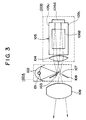
- Figure 3 shows the construction of a first embodiment of the present invention.
- Figure 4A shows the construction of a light source unit 100A in Figure 3.
- Figure 4B shows the construction of an image forming unit 100B in Figure 3.
- Figure 5A shows the construction of a liquid crystal device 106 when in a transmitting state.
- Figure 5B shows the construction of the liquid crystal device 106 when in a diffused state.
- Figure 6 shows the state of diffracted light when the liquid crystal device is in a diffused state.
- Figure 7 shows the construction of the essential portions of a second embodiment of the present invention.
- Figure 8 shows the construction of an apparatus according to a third embodiment of the present invention.
- Figure 3 shows the general construction of an embodiment of the projection type image display apparatus or projector of the present invention.
- a light beam emitted from a light source 101 is condensed on a reflecting mirror 103 by a rotatable elliptical mirror 102, and is directed toward a schlieren lens 104 by the reflecting mirror 103.
- This light beam is made into a parallel light beam by the schlieren lens 104, whereafter it is resolved into light beams of three colors, red, green and blue, by a cross dichroic mirror 105 having a pair of dichroic films crossing cruciformly, and these light beams are made to enter liquid crystal devices, i.e.
- the cross dichroic mirror 105 serves as a light separating optical system and also as a light combining optical system.
- the color image lights combined by the cross dichroic mirror 105 are condensed on an opening portion 107 by the schlieren lens 104, are projected onto a screen, not shown, by a projection lens 109 and form a color image on the screen.
- Figure 4A shows a light source unit 100A encircled by a dotted line in Figure 3 as it is seen from the schlieren lens 104 side.
- the light source unit 100A has a laterally long light emitting portion, and the opening portion 107 in a light intercepting portion 108 through which image display light passes and the reflecting mirror 103 also have a laterally long shape.
- the reflecting mirror 103 is herein shown as laterally long, but this is not requisite condition.
- the lengthwise direction of the light source 101, the opening portion 107 and the reflecting mirror 103 in Figure 4A corresponds to a direction perpendicular to the plane of the drawing sheet of Figure 3, in the apparatus of Figure 3.
- Figure 4B shows an image forming unit 100B encircled by a dotted line in Figure 3 as it is seen from above the cross dichroic mirror 105.
- the remaining green light beam is transmitted through each dichroic mirror and enters a liquid crystal device 106G for green.
- Figure 5 shows the construction of the liquid crystal device 106G for green of the three liquid crystal devices for three colors of Figure 4B as a representative one, and the constructions of the liquid crystal devices 106B and 106R for blue and red are the same as the construction of the liquid crystal device 106G for green.
- Each liquid crystal device actually assumes two-dimensional matrix structure vertically and horizontally divided into a predetermined number of picture elements, but here, a certain picture element of the liquid crystal device 106G is shown and the operation principle thereof will be described below.
- a diffraction grating 106G3 comprising a periodic relief structure having a pitch of the order of micron is formed so that the grooves (recesses) thereof may extend in a horizontal direction (a direction perpendicular to the plane of the drawing sheet) which is the direction in which the devices 106B and 106R are adjacent to the device 106G, and the intermediate layer 106G4 between the transparent (glass) substrate 106G1 and the diffraction grating 106G3 is impregnated with nematic liquid crystal molecules 106G5 having positive dielectric anisotropy.
- the interface of the transparent (glass) substrate 106G1 or the diffraction grating 106G3 is subjected to orientation treatment so that when as shown in Figure 5A, a switch SW is set to its ON position and there is brought about a transmission mode in which a voltage is applied, the major axes of the liquid crystal molecules 106G5 may become uniform in the direction of electric field perpendicular to the surfaces of the transparent (glass) substrates 106G1 and 106G2 and that when the switch SW is set to its OFF position and there is brought about a scattering mode in which no voltage is applied, the direction of the groove in the diffraction grating 106G3 and the major axes of the liquid crystal molecules 106G5 may become parallel to each other as shown in Figure 5B.
- the reference character 106G6 designates a quarter wavelength ( ⁇ /4) plate having its main axis in a direction forming an angle of 45° with respect to the direction of the groove in the diffraction grating 106G3, and the reference character 106G7 denotes a reflecting mirror formed of aluminum evaporated film or the like.
- the materials of the diffraction grating 106G3 and the liquid crystal molecules 106G5 are chosen so that the refractive index of the former and the ordinary refractive index n 0 of the latter may be equal to each other.
- the incident light is hardly diffracted because the refractive indices of the liquid crystal molecules 106G5 and the diffraction grating 106G3 for the incident light beam are equal to each other. Also, the diffraction of this incident light hardly takes place even after the incident light is reflected by the reflecting mirror 106G7 through the quarter wavelength ( ⁇ /4) plate 106G6, and the light recombined by the cross dichroic mirror 105 passes through the opening portion 107 and is projected onto the screen (see Figure 3).
- the polarized component which has not been diffracted at first is now chiefly diffracted because the polarized components in the horizontal directicn and the vertical direction change places with each other.
- both of the polarized components of the incident light which are orthogonal to each other are diffracted and therefore, the light beam diffracted and having changed its direction of travel does not pass through the opening portion, but is absorbed by the light intercepting portion 108 (see Figure 3).
- Figure 6 shows the chief direction of diffraction of the diffracted light from the liquid crystal device 106G described with reference to Figure 5. Since the grooves in the diffraction grating A06G3 of the device 106G are formed in the horizontal direction (the direction perpendicular to the plane of the drawing sheet) which is the direction in which the neighboring device lies, diffusing power has directionality in the vertical direction, and diffraction takes place chiefly in the vertical direction (in the plane of the drawing sheet) from a point ⁇ 1 on the liquid crystal device 106G.
- a light beam of a great angle of diffraction as indicated by ⁇ 1 enters the upper and surface 105U or the lower end surface 105L of the cross dichroic mirror 105, but the direct entrance of the light beam into the liquid crystal devices 106R and 106B for the other colors hardly takes place.
- the upper and lower end surfaces 105U and 105L of the cross dichroic mirror 105 may be subjected to light absorption treatment to thereby intercept the light.
- the cross dichroic mirror 105 is comprised of a prism, if the upper and lower end surfaces 105U and 105 L thereof are made into mirror surfaces and the angle of incidence of the reflected diffracted light, when the diffracted light has been intactly totally reflected onto the schlieren lens 104, is set to a great angle, this reflected diffracted light will impinge on the light intercepting portion outside the opening portion 107 and therefore, no problem will arise (see Figure 3).
- the direction of travel of the diffracted light is not toward the liquid crystal devices for the other colors and therefore, it never happens that unnecessary light is scattered by the liquid crystal devices for the other colors and deteriorates the quality of the image on the screen.
- the shape of the light emitting portion of the light source 101 is made into a horizontally long shape as shown in Figure 2, and in accordance therewith, the opening portion 107 onto which the horizontally long image of the light source 101 is projected through each liquid crystal device is also made into a horizontally long shape.
- the diffraction in each liquid crystal device takes place intensely in the vertical direction which is the direction of the mirror diameter of the opening portion 107 and therefore, the angle of diffraction necessary for the display of the image may be small.
- each liquid crystal device is designed to diffract the incident light chiefly in the other direction than toward the liquid crystal devices for the other colors, whereby the occurrence of flare or ghost images can be decreased or prevented. Also, the emergent light from each liquid crystal device is projected by a single projection lens, whereby a compact construction is provided. Also, by keeping the constant relation as described above, it becomes easy to obtain an image of high contrast.
- the light source 101 used is of a shape in which the light emitting portion thereof is horizontally long
- a light source merely having a substantially spherical light emitting portion or to combine such light source with an anamorphic optical system to thereby project a horizontally long light source image onto the reflecting mirror 103.
- the construction of the illuminating system is not restricted to that disclosed herein.
- the orientation of the liquid crystal molecules 106G5 is substantially complete with respect to a predetermined direction in the liquid crystal layer and therefore, diffraction or scattering in that direction has hardly taken place.
- the liquid crystal is optically considerably regularly distributed with respect to at least one direction in the liquid crystal layer, whereby the diffusion characteristic of the liquid crystal devices can be endowed with directionality, and the direction in which diffusing power is strong (the direction in which diffused light is chiefly directed) is made equal to a direction differing from the direction in which the liquid crystal devices for the other colors are adjacent to each other, preferably the vertical direction, whereby the incidence of ghost or flare light onto the screen can be mitigated.
- the first embodiment is one in which the present invention is applied to a projection type display apparatus or projector, respectively, provided with reflection type liquid crystal devices, but the present invention is also applicable to a projection type display apparatus or projector, respectively, provided with transmission type liquid crystal devices.
- An example of the liquid crystal device used in the construction as shown, for example, in Figure 2 is shown in Figure 7.
- ⁇ /2 half wavelength
- Figure 8 shows a so-called multiple-lens projection type display apparatus or projector, respectively, provided with a light source 601, a reflector 602, a condenser lens 603, dichroic mirrors 604, 605 and a reflecting mirror 606 which together constitute an illuminating system similar to the system comprising the members 701 to 706 of Figure 2 and a color resolving system, and comprised of liquid crystal devices 610R, 610G and 610B for respective colors and projection lens systems 611R, 611G and 611B for respective colors.
- the liquid crystal devices 610R, 610G and 610B are comprised of those shown in the first or second embodiment.
- a light intercepting plate provided with a predetermined opening and for intercepting diffracted light is provided in each of the projection lens systems 611R, 611G and 611B.
- the intervals between the liquid crystal devices 610R, 610G and 610B can be made small and therefore, the deviation of the optical axis inherent to the multiple-lens type which occurs among the projection lens systems 611R, 611G and 611B can be reduced. Accordingly, the shift of color caused by the difference between the angles of incidence of the imaging light beams of respective colors onto a screen, not shown, can be decreased.
- the idea of the present invention can be applied not only to the devices described above, but also to other light modulation devices of the diffusion type.
- the idea of the present invention can also be applied to an apparatus in which light transmitted through the picture elements of a light modulation device is intercepted and light scattered or diffracted by the picture elements is projected onto a screen to thereby form an image.
- the present invention has the effect that an image from which ghost or flare is mitigated or eliminated can be projected, because as described above, other devices are not disposed in the direction in which the diffusing power of a certain device is strong.
Landscapes
- Engineering & Computer Science (AREA)
- Multimedia (AREA)
- Signal Processing (AREA)
- Liquid Crystal (AREA)
- Projection Apparatus (AREA)
- Control Of Indicators Other Than Cathode Ray Tubes (AREA)
Claims (2)
- Projecteur comprenant :des moyens (103) pour fournir des premier et second faisceaux de rayonnement ;des premier et second appareils (106V, 106B; 610V, 610B) de modulation de lumière ayant chacun une structure matricielle divisée horizontalement et verticalement en un ensemble de pixels, dans lequel chacun dudit ensemble de pixels forme l'un quelconque d'un faisceau dévié et d'un faisceau non dévié en fonction d'un signal d'entrée ; etun système (105, 104, 107, 109; 603, 604, 605, 611B, 611V) optique de projection ;dans lequel ledit projecteur forme une image en projetant l'un quelconque dudit faisceau dévié et dudit faisceau non dévié provenant de chacun desdits appareils de modulation de lumière au moyen dudit système (105, 104, 107, 109 ; 603, 604,605, 611B, 611V) optique de projection;caractérisé en ce que
chaque pixel desdits premier et second appareils (106V, 106B, 610V, 610B) de modulation de lumière comprendune paire de substrats (106V1, 106V2; 561, 562) transparents en face l'un de l'autre, les surfaces de ladite paire de substrats (106V1, 106V2; 561, 562) transparents qui sont adjacentes à l'autre desdits substrats ayant des électrodes transparentes formées sur celles-ci ;une structure (106V3; 564) de réseau de diffraction formée sur ladite électrode transparente de l'un de ladite paire de substrats (106V1, 106V2; 561, 562) transparents, un ensemble de rainures dans ladite structure (106V3; 564) de réseau de diffraction s'étendant dans une direction à laquelle l'autre appareil de modulation de lumière est adjacent ;une couche (106V5; 565) de cristal liquide ayant une propriété de biréfringence et remplissant l'espace entre l'électrode transparente de l'autre de ladite paire de substrats (106V1, 106V2; 561, 562) transparents et ladite structure (106V3, 564) de réseau de diffraction ;des moyens d'attaque utilisant lesdites électrodes transparentes pour commander la direction d'orientation d'un ensemble de molécules de cristal liquide dans ladite couche (106V5; 565) de cristal liquide afin, dans un premier mode, de diriger ainsi ledit ensemble de molécules de cristal liquide dans une direction sensiblement perpendiculaire auxdites surfaces, et, dans un second mode, de diriger ledit ensemble de molécules de cristal liquide dans une direction sensiblement parallèle auxdites surfaces ; etdes moyens (106V6, 106V7) réfléchissants munis d'une lame λ/4 (106V6) disposée sur l'un de ladite paire de substrats (106V1, 106V2; 561, 562) transparents qui est éloigné dudit système (105, 104, 107, 109; 603, 604, 605, 611B, 611V) optique de projection ; lesdits moyens (106V6, 106V7) réfléchissants faisant tourner d'environ 90° les plans de polarisation des deux composantes polarisées dudit faisceau incident transmis à travers ladite paire de substrats (106V1, 106V2; 561, 562) transparents qui sont orthogonaux l'un à l'autre et faisant de nouveau pénétrer ledit faisceau incident dans ladite paire de substrats (106V1, 106V2; 561, 562) transparents. - Projecteur comprenant :des moyens (103) pour fournir des premier et second faisceaux de rayonnement ;des premier et second appareils (106V, 106B; 610V, 610B) de modulation de lumière, ayant chacun une structure matricielle divisée horizontalement et verticalement en un ensemble de pixels, dans lequel chacun dudit ensemble de pixels forme l'un quelconque d'un faisceau dévié et d'un faisceau non dévié en fonction d'un signal d'entrée ; etun système (105, 104, 107, 109; 603, 604, 605, 611B, 611V) optique de projection ;dans lequel ledit projecteur forme une image en projetant l'un quelconque dudit faisceau dévié et dudit faisceau non dévié provenant dudit appareil de modulation de lumière au moyen dudit système (105, 104, 107, 109; 603, 604, 605, 611B, 611V) optique de projection ;caractérisé en ce que
chacun desdits pixel desdits premier et second appareils de modulation de lumière comprend en outreune paire de substrats (561', 562') transparents en face l'un de l'autre, les surfaces de ladite paire de substrats (561', 562') transparents qui sont adjacentes à l'autre desdits substrats ayant des électrodes transparentes formées sur celles-ci ;une structure (564') de réseau de diffraction formée sur ladite électrode transparente de l'un de ladite paire de substrats (561', 562') transparents, un ensemble de rainures dans ladite structure (564') de réseau de diffraction s'étendant dans une direction à laquelle l'autre appareil de modulation de lumière est adjacent ;une couche (565') de cristal liquide ayant une propriété de biréfringence et remplissant l'espace entre l'électrode transparente de l'autre de ladite paire de substrats (561', 562') transparents et ladite structure (564') de réseau de diffraction ;des moyens d'attaque utilisant lesdites électrodes transparentes de ladite paire de substrats (561, 562) transparents et lesdites électrodes transparentes de ladite paire de substrats (561', 562') transparents pour commander respectivement la direction d'orientation d'un ensemble de molécules de cristal liquide dans l'autre couche (565) de cristal liquide et dans ladite couche (565') de cristal liquide, pour ainsi diriger, dans un premier mode, ledit ensemble de molécules de cristal liquide de chacune desdites couches (565, 565') de cristal liquide dans une direction sensiblement perpendiculaire auxdites surfaces ; et, dans un seconde mode, diriger ledit ensemble de molécules de cristal liquide de chacune desdites couches (565, 565') de cristal liquide dans une direction sensiblement parallèle auxdites surfaces ;une lame λ/2 (566) disposée sur le trajet du faisceau incident entre ladite paire de substrats (561, 562) transparents et ladite paire de substrats (561', 562') transparents, ladite lame λ/2 faisant tourner d'environ 90° les plans de polarisation des deux composantes polarisées dudit faisceau incident transmis à travers ladite paire de substrats (561, 562) transparents qui sont disposés perpendiculairement l'un à l'autre, et faisant en sorte que ledit faisceau incident pénètre dans ladite paire de substrats (561', 562') transparents.
Applications Claiming Priority (2)
| Application Number | Priority Date | Filing Date | Title |
|---|---|---|---|
| JP2415302A JP2656666B2 (ja) | 1990-12-27 | 1990-12-27 | 投射型表示装置 |
| JP415302/90 | 1990-12-27 |
Publications (3)
| Publication Number | Publication Date |
|---|---|
| EP0492637A2 EP0492637A2 (fr) | 1992-07-01 |
| EP0492637A3 EP0492637A3 (en) | 1992-10-28 |
| EP0492637B1 true EP0492637B1 (fr) | 1997-05-21 |
Family
ID=18523678
Family Applications (1)
| Application Number | Title | Priority Date | Filing Date |
|---|---|---|---|
| EP91122278A Expired - Lifetime EP0492637B1 (fr) | 1990-12-27 | 1991-12-27 | Projecteur muni de plusieurs générateurs d'images |
Country Status (5)
| Country | Link |
|---|---|
| US (1) | US5333021A (fr) |
| EP (1) | EP0492637B1 (fr) |
| JP (1) | JP2656666B2 (fr) |
| CA (1) | CA2058506C (fr) |
| DE (1) | DE69126196T2 (fr) |
Families Citing this family (19)
| Publication number | Priority date | Publication date | Assignee | Title |
|---|---|---|---|---|
| JP2651972B2 (ja) * | 1992-03-04 | 1997-09-10 | 株式会社半導体エネルギー研究所 | 液晶電気光学装置 |
| US5659409A (en) * | 1992-10-09 | 1997-08-19 | Ag Technology Co., Ltd. | Light source apparatus using a cone-like material and an applied apparatus thereof |
| US5534949A (en) * | 1994-04-08 | 1996-07-09 | Hughes Aircraft Company | Two channel field sequential color display system |
| US5975703A (en) | 1996-09-30 | 1999-11-02 | Digital Optics International | Image projection system |
| US6243152B1 (en) * | 1996-12-17 | 2001-06-05 | Duke University | Contrast polymer dispersed liquid crystal projection display system |
| DE69803543T2 (de) * | 1997-05-07 | 2002-09-05 | Koninklijke Philips Electronics N.V., Eindhoven | Bildprojektionssystem |
| GB2325056A (en) * | 1997-05-09 | 1998-11-11 | Sharp Kk | Polarisation independent optical phase modulator |
| WO1999056158A1 (fr) * | 1998-04-24 | 1999-11-04 | Minnesota Mining And Manufacturing Company | Composants optiques avec diffuseur auto-adhésif |
| US6490076B2 (en) * | 2001-01-11 | 2002-12-03 | Hrl Laboratories, Llc | Optical phased array for depolarized optical beam control |
| JP4967201B2 (ja) * | 2001-07-10 | 2012-07-04 | 株式会社ニコン | 投射型表示装置 |
| US7891818B2 (en) * | 2006-12-12 | 2011-02-22 | Evans & Sutherland Computer Corporation | System and method for aligning RGB light in a single modulator projector |
| EP2247978A4 (fr) | 2008-01-30 | 2012-12-26 | Qualcomm Mems Technologies Inc | Système d éclairage mince |
| US8721149B2 (en) | 2008-01-30 | 2014-05-13 | Qualcomm Mems Technologies, Inc. | Illumination device having a tapered light guide |
| JP2009223936A (ja) * | 2008-03-14 | 2009-10-01 | Ricoh Co Ltd | 光ピックアップおよびこれを用いる光情報処理装置 |
| US8358317B2 (en) | 2008-05-23 | 2013-01-22 | Evans & Sutherland Computer Corporation | System and method for displaying a planar image on a curved surface |
| US8702248B1 (en) | 2008-06-11 | 2014-04-22 | Evans & Sutherland Computer Corporation | Projection method for reducing interpixel gaps on a viewing surface |
| US8077378B1 (en) | 2008-11-12 | 2011-12-13 | Evans & Sutherland Computer Corporation | Calibration system and method for light modulation device |
| US9641826B1 (en) | 2011-10-06 | 2017-05-02 | Evans & Sutherland Computer Corporation | System and method for displaying distant 3-D stereo on a dome surface |
| DE112016002375T5 (de) * | 2015-05-27 | 2018-02-15 | Panasonic Intellectual Property Management Co., Ltd. | Optische Vorrichtung |
Family Cites Families (16)
| Publication number | Priority date | Publication date | Assignee | Title |
|---|---|---|---|---|
| US3843231A (en) * | 1971-04-22 | 1974-10-22 | Commissariat Energie Atomique | Liquid crystal diffraction grating |
| US4729640A (en) * | 1984-10-03 | 1988-03-08 | Canon Kabushiki Kaisha | Liquid crystal light modulation device |
| DE3605516A1 (de) * | 1985-02-21 | 1986-09-04 | Canon K.K., Tokio/Tokyo | Optisches funktionselement sowie optische funktionsvorrichtung |
| JPS62180343A (ja) * | 1986-02-04 | 1987-08-07 | Hitachi Ltd | 投射光学装置 |
| US4850681A (en) * | 1986-04-07 | 1989-07-25 | Canon Kabushiki Kaisha | Optical modulation device |
| US4822146A (en) * | 1986-04-07 | 1989-04-18 | Canon Kabushiki Kaisha | Optical modulation element |
| US4989076A (en) * | 1987-01-27 | 1991-01-29 | Canon Kabushiki Kaisha | Video projection apparatus |
| JPS63216025A (ja) * | 1987-03-04 | 1988-09-08 | Seiko Epson Corp | 投写型カラ−表示装置 |
| US4772102A (en) * | 1987-05-18 | 1988-09-20 | Taliq Corporation | Display with light traps between reflector and scattering means |
| JPS63292892A (ja) * | 1987-05-26 | 1988-11-30 | Kawasaki Heavy Ind Ltd | カラ−画像投影装置 |
| JP2569645B2 (ja) * | 1987-12-07 | 1997-01-08 | キヤノン株式会社 | 反射型光変調装置 |
| US5097323A (en) * | 1988-01-25 | 1992-03-17 | Casio Computer Co., Ltd. | Liquid crystal projector |
| JPH0253030A (ja) * | 1988-08-18 | 1990-02-22 | Matsushita Electric Ind Co Ltd | 投射型カラー表示装置 |
| GB2226174A (en) * | 1988-12-14 | 1990-06-20 | Philips Electronic Associated | Liquid crystal display devices |
| JP2782520B2 (ja) * | 1988-12-14 | 1998-08-06 | 旭光学工業株式会社 | 液晶投影表示装置 |
| US5108172A (en) * | 1989-08-11 | 1992-04-28 | Raf Electronics Corp. | Active matrix reflective image plane module and projection system |
-
1990
- 1990-12-27 JP JP2415302A patent/JP2656666B2/ja not_active Expired - Fee Related
-
1991
- 1991-12-20 US US07/811,020 patent/US5333021A/en not_active Expired - Fee Related
- 1991-12-24 CA CA002058506A patent/CA2058506C/fr not_active Expired - Fee Related
- 1991-12-27 EP EP91122278A patent/EP0492637B1/fr not_active Expired - Lifetime
- 1991-12-27 DE DE69126196T patent/DE69126196T2/de not_active Expired - Fee Related
Non-Patent Citations (1)
| Title |
|---|
| PATENT ABSTRACTS OF JAPAN vol. 12, no. 25 (P-659)26 January 1988 & JP-A-62 180 343 * |
Also Published As
| Publication number | Publication date |
|---|---|
| US5333021A (en) | 1994-07-26 |
| EP0492637A3 (en) | 1992-10-28 |
| CA2058506A1 (fr) | 1992-06-28 |
| CA2058506C (fr) | 1995-05-30 |
| DE69126196D1 (de) | 1997-06-26 |
| DE69126196T2 (de) | 1997-11-13 |
| EP0492637A2 (fr) | 1992-07-01 |
| JP2656666B2 (ja) | 1997-09-24 |
| JPH04232917A (ja) | 1992-08-21 |
Similar Documents
| Publication | Publication Date | Title |
|---|---|---|
| EP0492637B1 (fr) | Projecteur muni de plusieurs générateurs d'images | |
| EP1063554B1 (fr) | Luminaire à polarisation et projecteur l'utilisant | |
| US6588906B2 (en) | Single-panel color image display apparatus and method thereof | |
| US5283600A (en) | LCD projector | |
| KR100481400B1 (ko) | 화상표시장치 | |
| EP1420597A2 (fr) | Projecteur | |
| EP0537708A1 (fr) | Projecteur en couleurs | |
| US5798866A (en) | Picture display device with two microlens arrays | |
| WO1998023990A1 (fr) | Module de projection d'image et dispositif de projection d'images pourvu d'un tel module | |
| JP3060230B2 (ja) | 画像投射装置 | |
| US6746123B2 (en) | Projector for preventing light loss | |
| US6024451A (en) | Illumination system and image projection device provided with such an illumination system | |
| JP3657347B2 (ja) | 液晶スクリーンの照明装置 | |
| US20090046254A1 (en) | Projector system | |
| KR0184364B1 (ko) | 반사형 광모듈레이터를 이용한 투사형 입체화상표시장치 | |
| JP3460456B2 (ja) | 投写型表示装置 | |
| KR20000003888A (ko) | 투사형 화상 표시 장치 | |
| JP2001201793A (ja) | プロジェクタ | |
| KR19980039526A (ko) | 광 투영 방법 및 이를 수행하기 위한 고휘도 액정 프로젝터 | |
| JPH10111535A (ja) | 液晶投射装置 | |
| KR19990043705A (ko) | 투사형 화상 표시 장치 | |
| HK1033485B (en) | Polarization luminaire and projector using it | |
| HK1033361B (en) | Polarization luminaire and projector using it | |
| HK1014271B (en) | Polarized lighting apparatus and projection type display device |
Legal Events
| Date | Code | Title | Description |
|---|---|---|---|
| PUAI | Public reference made under article 153(3) epc to a published international application that has entered the european phase |
Free format text: ORIGINAL CODE: 0009012 |
|
| AK | Designated contracting states |
Kind code of ref document: A2 Designated state(s): DE FR GB IT NL |
|
| PUAL | Search report despatched |
Free format text: ORIGINAL CODE: 0009013 |
|
| AK | Designated contracting states |
Kind code of ref document: A3 Designated state(s): DE FR GB IT NL |
|
| 17P | Request for examination filed |
Effective date: 19930315 |
|
| 17Q | First examination report despatched |
Effective date: 19950216 |
|
| GRAG | Despatch of communication of intention to grant |
Free format text: ORIGINAL CODE: EPIDOS AGRA |
|
| GRAH | Despatch of communication of intention to grant a patent |
Free format text: ORIGINAL CODE: EPIDOS IGRA |
|
| GRAH | Despatch of communication of intention to grant a patent |
Free format text: ORIGINAL CODE: EPIDOS IGRA |
|
| GRAA | (expected) grant |
Free format text: ORIGINAL CODE: 0009210 |
|
| AK | Designated contracting states |
Kind code of ref document: B1 Designated state(s): DE FR GB IT NL |
|
| REF | Corresponds to: |
Ref document number: 69126196 Country of ref document: DE Date of ref document: 19970626 |
|
| ET | Fr: translation filed | ||
| PLBE | No opposition filed within time limit |
Free format text: ORIGINAL CODE: 0009261 |
|
| STAA | Information on the status of an ep patent application or granted ep patent |
Free format text: STATUS: NO OPPOSITION FILED WITHIN TIME LIMIT |
|
| 26N | No opposition filed | ||
| REG | Reference to a national code |
Ref country code: GB Ref legal event code: IF02 |
|
| PGFP | Annual fee paid to national office [announced via postgrant information from national office to epo] |
Ref country code: NL Payment date: 20041205 Year of fee payment: 14 |
|
| PGFP | Annual fee paid to national office [announced via postgrant information from national office to epo] |
Ref country code: FR Payment date: 20041208 Year of fee payment: 14 |
|
| PGFP | Annual fee paid to national office [announced via postgrant information from national office to epo] |
Ref country code: GB Payment date: 20041222 Year of fee payment: 14 |
|
| PGFP | Annual fee paid to national office [announced via postgrant information from national office to epo] |
Ref country code: DE Payment date: 20041223 Year of fee payment: 14 |
|
| PG25 | Lapsed in a contracting state [announced via postgrant information from national office to epo] |
Ref country code: IT Free format text: LAPSE BECAUSE OF NON-PAYMENT OF DUE FEES Effective date: 20051227 Ref country code: GB Free format text: LAPSE BECAUSE OF NON-PAYMENT OF DUE FEES Effective date: 20051227 |
|
| PG25 | Lapsed in a contracting state [announced via postgrant information from national office to epo] |
Ref country code: NL Free format text: LAPSE BECAUSE OF NON-PAYMENT OF DUE FEES Effective date: 20060701 Ref country code: DE Free format text: LAPSE BECAUSE OF NON-PAYMENT OF DUE FEES Effective date: 20060701 |
|
| GBPC | Gb: european patent ceased through non-payment of renewal fee |
Effective date: 20051227 |
|
| PG25 | Lapsed in a contracting state [announced via postgrant information from national office to epo] |
Ref country code: FR Free format text: LAPSE BECAUSE OF NON-PAYMENT OF DUE FEES Effective date: 20060831 |
|
| NLV4 | Nl: lapsed or anulled due to non-payment of the annual fee |
Effective date: 20060701 |
|
| REG | Reference to a national code |
Ref country code: FR Ref legal event code: ST Effective date: 20060831 |