EP0492736A1 - Raboteuse avec montage de palier amélioré - Google Patents
Raboteuse avec montage de palier amélioré Download PDFInfo
- Publication number
- EP0492736A1 EP0492736A1 EP91203387A EP91203387A EP0492736A1 EP 0492736 A1 EP0492736 A1 EP 0492736A1 EP 91203387 A EP91203387 A EP 91203387A EP 91203387 A EP91203387 A EP 91203387A EP 0492736 A1 EP0492736 A1 EP 0492736A1
- Authority
- EP
- European Patent Office
- Prior art keywords
- shaft
- planing
- planing knife
- bearing
- carrier
- Prior art date
- Legal status (The legal status is an assumption and is not a legal conclusion. Google has not performed a legal analysis and makes no representation as to the accuracy of the status listed.)
- Granted
Links
- 238000003754 machining Methods 0.000 claims abstract description 9
- 238000010276 construction Methods 0.000 description 4
- 238000003466 welding Methods 0.000 description 2
- 238000003801 milling Methods 0.000 description 1
Images
Classifications
-
- B—PERFORMING OPERATIONS; TRANSPORTING
- B27—WORKING OR PRESERVING WOOD OR SIMILAR MATERIAL; NAILING OR STAPLING MACHINES IN GENERAL
- B27G—ACCESSORY MACHINES OR APPARATUS FOR WORKING WOOD OR SIMILAR MATERIALS; TOOLS FOR WORKING WOOD OR SIMILAR MATERIALS; SAFETY DEVICES FOR WOOD WORKING MACHINES OR TOOLS
- B27G13/00—Cutter blocks; Other rotary cutting tools
- B27G13/02—Cutter blocks; Other rotary cutting tools in the shape of long arbors, i.e. cylinder cutting blocks
- B27G13/04—Securing the cutters by mechanical clamping means
-
- B—PERFORMING OPERATIONS; TRANSPORTING
- B27—WORKING OR PRESERVING WOOD OR SIMILAR MATERIAL; NAILING OR STAPLING MACHINES IN GENERAL
- B27C—PLANING, DRILLING, MILLING, TURNING OR UNIVERSAL MACHINES FOR WOOD OR SIMILAR MATERIAL
- B27C1/00—Machines for producing flat surfaces, e.g. by rotary cutters; Equipment therefor
- B27C1/10—Hand planes equipped with power-driven cutter blocks
-
- Y—GENERAL TAGGING OF NEW TECHNOLOGICAL DEVELOPMENTS; GENERAL TAGGING OF CROSS-SECTIONAL TECHNOLOGIES SPANNING OVER SEVERAL SECTIONS OF THE IPC; TECHNICAL SUBJECTS COVERED BY FORMER USPC CROSS-REFERENCE ART COLLECTIONS [XRACs] AND DIGESTS
- Y10—TECHNICAL SUBJECTS COVERED BY FORMER USPC
- Y10T—TECHNICAL SUBJECTS COVERED BY FORMER US CLASSIFICATION
- Y10T409/00—Gear cutting, milling, or planing
- Y10T409/30—Milling
- Y10T409/306216—Randomly manipulated, work supported, or work following device
-
- Y—GENERAL TAGGING OF NEW TECHNOLOGICAL DEVELOPMENTS; GENERAL TAGGING OF CROSS-SECTIONAL TECHNOLOGIES SPANNING OVER SEVERAL SECTIONS OF THE IPC; TECHNICAL SUBJECTS COVERED BY FORMER USPC CROSS-REFERENCE ART COLLECTIONS [XRACs] AND DIGESTS
- Y10—TECHNICAL SUBJECTS COVERED BY FORMER USPC
- Y10T—TECHNICAL SUBJECTS COVERED BY FORMER US CLASSIFICATION
- Y10T409/00—Gear cutting, milling, or planing
- Y10T409/30—Milling
- Y10T409/306216—Randomly manipulated, work supported, or work following device
- Y10T409/306552—Randomly manipulated
Definitions
- the invention relates to a device for performing a machining movement with at least one rotatable planing knife, comprising:
- Such devices are generally known.
- the second shaft is fixedly attached to the planing knife holder, and the second shaft is mounted in the second bearing that is fixedly attached in the carrier. It is also possible for both shafts to be formed into one entity.
- a groove has to be machined, for example planed, with such a machine forming part of the prior art, the problem arises that the maximum depth of such a groove for machining is limited. This limitation is formed by the distance between the bottom edge of the planing knife holder and the bottom edge of the carrier in which the bearings are fixed.
- the object of the invention is to provide such a device with which grooves of a greater depth can be machined.
- the object of the invention is to provide such a known device wherein, while preserving an acceptably dimensioned construction, the depth of a groove for machining can be enlarged.
- the second shaft is connected fixedly to the carrier, and the second bearing is arranged on the shaft inside the body of the planing knife holder.
- the second shaft has to be fixed directly onto the carrier, without interposing of a bearing, on the side of the second shaft the distance between the underside of the carrier and the underside of the planing knife holder is enlarged; and this by the difference between the internal and the external diameter of the bearing.
- Such a drive wheel can take the form of a gear wheel, that is driven by a pinion fixed on the shaft of an electric motor, or by a pulley or a chain wheel for driving by a belt or chain.
- the second bearing is formed by a needle bearing. This has the advantage that the diameter of the planing knife holder can be reduced.
- the first bearing is also formed by a needle bearing. This enlarges the maximum groove depth on the side of the first bearing.
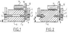
- a first bearing 2 that is preferably formed by a needle bearing and in which a first shaft 3 is bearing mounted.
- a second bearing 4 that is preferably formed by a needle bearing and in which a second shaft 5 is bearing mounted. Both shafts 3, 5 lie mutually in line.
- the planing knife holder 6 Arranged around the shafts and concentrically therewith is the planing knife holder 6 in which two planing knives 7, 8 are placed in positions diametrically opposite one another.
- a gear wheel 9 that is in engagement with a pinion 12 fixed on the shaft 10 of an electric motor 11.
- the electric motor 11 which is otherwise fixedly attached in the carrier in a manner not shown, drives the shaft 3, and therewith the planing knife holder 6, via the shaft 10, the pinion 12 and the gear wheel 9.
- the maximum groove depth for machining is limited by the dimension A.
- the dimension A can be influenced by reducing the thickness of the portion of the carrier 1 under the bearing 4, which is not desirable for reasons of strength, or by increasing the diameter of the planing knife holder 6, which likewise meets with dimensional drawbacks.
- the second bearing is arranged inside the body of the planing knife holder 6.
- the shaft 5 extends inside this bearing.
- the shaft 5 is directly connected to the carrier 1 for example by welding or other means. Due to the absence of the second bearing 4 in the wall of the carrier 1 and the fixing of the shaft 5 directly to the carrier, the maximum groove depth for machining on the left-hand side of the drawing is increased to the dimension B.
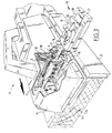
- Shown in fig. 3 is a planing machine 13 which is formed by a housing 14, under which a foot plate 15 is fixed.
- a foot plate 15 Arranged on the foot plate 15 is an upward extending side wall 16 in which a first bearing 2 is arranged.
- a second side wall 17 is arranged on the other side of the machine. Both side walls 16, 17 form a carrier in which the electric motor 11 is also fixed.
- the first shaft 3 is bearing mounted in the first bearing 2, while the second shaft 5 is fixedly attached to the second side wall 17, for example by welding.
- the second bearing 4 is arranged on the free end of the second shaft.
- the gear wheel 9 Further arranged on the first shaft 3 is the gear wheel 9 which is in engagement with the pinion 12 that is fixed onto the shaft 10 of the electric motor 11.
- an adjusting device 18 which is formed by plate 19 which is slidably connected by means of a dovetail joint 20 to a bottom plate 21 which is fixedly connected to a frame plate 22.
- the dovetail joint allows sideways movement of the planing machine relative to the frame plate 22, so that the width of a groove 24 to be arranged in a workpiece 23 for machining can be adjusted herewith.
- a tap end 25 which extends through a slot 25 arranged in the top plate 19 is arranged for fixing the setting.
- a wing nut 27 is turned on the tap end 25.
- the workpiece 23 is guided here by guide means not shown in the drawing, wherein it is moved through beneath the planing machine, and wherein the planing knives fixed in the rotating planing knife holder 6 plane off material from the workpiece. It will be apparent herein that due to the steps according to the invention the maximum allowable depth of the groove for planing out is increased considerably.
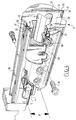
- Fig. 4 gives a detail view of the planing knife holder 6 according to the invention.
- the planing knife holder 6 is formed by a basic body 28.
- the first shaft 3 is fixedly attached in and the second bearing 4 is received into the basic body 28.
- a planing knife setting plate 29 is arranged on both flat sides of the basic body 28.
- a planing knife 30 is arranged in the vicinity of one of the edges of the flat side of the basic body 28.
- the planing knife 30 is provided with a cutting surface 31 on both long edges, while a groove 32 is arranged in the middle of one of the sides of the planing knife 30.
- the planing knife setting plate 29 is provided with an edge 33 which engages into the groove arranged in the planing knife 30.
- the planing knife setting plate 29 is connected to the basic body 28 by means of bolt 38.
- a recess 34 is for carrying away chips.
- planing knife clamp plate 35 which is fixed in the basic body 28 by means of bolts 36.
- the planing knife clamp plate 35 is provided with bent edges 37 which, when the bolts 36 are tightened, exerts a force on the planing knife setting plate 29 whereby the planing knife 30 is fixed.
- the above construction allows of rapid exchange or turning over of the planing knife 30 in order to use both cutting surfaces 31 of the planing knives 30.
- the bolts 36 have to be released, whereafter the planing knife can be pushed out sideways and pushed in again after being turned over, wherein the position of the planing knife is maintained by the planing knife setting plate.
- the planing knife clamp plate 35 also prevents excessive noise generation.
Landscapes
- Life Sciences & Earth Sciences (AREA)
- Engineering & Computer Science (AREA)
- Mechanical Engineering (AREA)
- Wood Science & Technology (AREA)
- Forests & Forestry (AREA)
- Harvester Elements (AREA)
- Storage Of Fruits Or Vegetables (AREA)
- Filling Or Emptying Of Bunkers, Hoppers, And Tanks (AREA)
- Structure Of Belt Conveyors (AREA)
- Mounting Of Bearings Or Others (AREA)
- Dovetailed Work, And Nailing Machines And Stapling Machines For Wood (AREA)
- Constituent Portions Of Griding Lathes, Driving, Sensing And Control (AREA)
- Milling, Drilling, And Turning Of Wood (AREA)
Applications Claiming Priority (2)
| Application Number | Priority Date | Filing Date | Title |
|---|---|---|---|
| NL9002865A NL9002865A (nl) | 1990-12-21 | 1990-12-21 | Schaaf met verbeterde lagering. |
| NL9002865 | 1990-12-21 |
Publications (3)
| Publication Number | Publication Date |
|---|---|
| EP0492736A1 true EP0492736A1 (fr) | 1992-07-01 |
| EP0492736B1 EP0492736B1 (fr) | 1997-10-01 |
| EP0492736B2 EP0492736B2 (fr) | 2001-08-08 |
Family
ID=19858209
Family Applications (1)
| Application Number | Title | Priority Date | Filing Date |
|---|---|---|---|
| EP91203387A Expired - Lifetime EP0492736B2 (fr) | 1990-12-21 | 1991-12-20 | Raboteuse avec montage de palier amélioré |
Country Status (8)
| Country | Link |
|---|---|
| US (1) | US5213457A (fr) |
| EP (1) | EP0492736B2 (fr) |
| JP (1) | JPH04307202A (fr) |
| AT (1) | ATE158746T1 (fr) |
| AU (1) | AU649755B2 (fr) |
| CA (1) | CA2057570A1 (fr) |
| DE (1) | DE69127803T3 (fr) |
| NL (1) | NL9002865A (fr) |
Cited By (3)
| Publication number | Priority date | Publication date | Assignee | Title |
|---|---|---|---|---|
| EP0618052A1 (fr) * | 1993-03-30 | 1994-10-05 | Festo KG | Raboteuse à main |
| GB2345027A (en) * | 1998-11-19 | 2000-06-28 | Bosch Gmbh Robert | Hand-held planning machine |
| WO2007093821A1 (fr) * | 2006-02-18 | 2007-08-23 | Gmca Pty Ltd | Outil motorise pour aplanir |
Families Citing this family (3)
| Publication number | Priority date | Publication date | Assignee | Title |
|---|---|---|---|---|
| US7503357B2 (en) * | 2006-04-25 | 2009-03-17 | Bor-Yann Chuang | Swiftly adjusting device for a blade shaft of a planer |
| EP4292787A1 (fr) | 2022-04-25 | 2023-12-20 | Milwaukee Electric Tool Corporation | Outil de rabotage manuel |
| CN120619449A (zh) * | 2025-05-30 | 2025-09-12 | 江苏朝阳高温线缆有限公司 | 一种绝缘材料加工用刨床 |
Citations (7)
| Publication number | Priority date | Publication date | Assignee | Title |
|---|---|---|---|---|
| GB295348A (en) * | 1925-09-15 | 1928-08-10 | Bruno Simonides | A portable electrically driven machine for planing, grinding, polishing, drilling, milling, sawing and other cutting operations |
| US2540258A (en) * | 1945-08-14 | 1951-02-06 | Thomas J Harris | Hand-operated electric powered dresser |
| US3171454A (en) * | 1963-07-30 | 1965-03-02 | Wilton Corp | Means for adjusting positions of jointer cutters |
| US3207195A (en) * | 1963-02-13 | 1965-09-21 | Wen Products Inc | Electric hand plane |
| FR1520140A (fr) * | 1967-04-21 | 1968-04-05 | Scheer & Cie C F | Raboteuse à main |
| EP0045730A2 (fr) * | 1980-08-05 | 1982-02-10 | Gunnar Harry Lindkvist | Raboteuse électrique à main |
| US4382729A (en) * | 1980-10-02 | 1983-05-10 | Black & Decker Inc. | Depth of cut adjustment mechanism for a power planer |
Family Cites Families (7)
| Publication number | Priority date | Publication date | Assignee | Title |
|---|---|---|---|---|
| US3253624A (en) * | 1964-06-15 | 1966-05-31 | Singer Co | Portable power-operated block planers |
| JPS55157103A (en) * | 1979-12-17 | 1980-12-06 | Pioneer Electronic Corp | Tone arm damping mechanism |
| EP0048303B1 (fr) * | 1980-10-07 | 1985-06-26 | Black & Decker Inc. | Porte-outil pour robot à main mû par un moteur |
| DE3239152A1 (de) * | 1982-10-22 | 1984-04-26 | Robert Bosch Gmbh, 7000 Stuttgart | Messerwalze fuer eine motorbetriebene handhobelmaschine |
| DE3246138A1 (de) * | 1982-12-14 | 1984-06-14 | Robert Bosch Gmbh, 7000 Stuttgart | Messerwalze, insbesondere fuer eine handhobelmaschine |
| JPH0643042B2 (ja) * | 1986-05-14 | 1994-06-08 | 株式会社芝浦製作所 | 手持ち電気鉋 |
| DE3621359C2 (de) * | 1986-06-26 | 1994-05-05 | Black & Decker Inc | Messerwalze für einen kraftgetriebenen Hobel |
-
1990
- 1990-12-21 NL NL9002865A patent/NL9002865A/nl not_active Application Discontinuation
-
1991
- 1991-12-12 US US07/806,597 patent/US5213457A/en not_active Expired - Lifetime
- 1991-12-13 AU AU89717/91A patent/AU649755B2/en not_active Ceased
- 1991-12-13 CA CA002057570A patent/CA2057570A1/fr not_active Abandoned
- 1991-12-20 EP EP91203387A patent/EP0492736B2/fr not_active Expired - Lifetime
- 1991-12-20 JP JP3355065A patent/JPH04307202A/ja active Pending
- 1991-12-20 AT AT91203387T patent/ATE158746T1/de not_active IP Right Cessation
- 1991-12-20 DE DE69127803T patent/DE69127803T3/de not_active Expired - Fee Related
Patent Citations (7)
| Publication number | Priority date | Publication date | Assignee | Title |
|---|---|---|---|---|
| GB295348A (en) * | 1925-09-15 | 1928-08-10 | Bruno Simonides | A portable electrically driven machine for planing, grinding, polishing, drilling, milling, sawing and other cutting operations |
| US2540258A (en) * | 1945-08-14 | 1951-02-06 | Thomas J Harris | Hand-operated electric powered dresser |
| US3207195A (en) * | 1963-02-13 | 1965-09-21 | Wen Products Inc | Electric hand plane |
| US3171454A (en) * | 1963-07-30 | 1965-03-02 | Wilton Corp | Means for adjusting positions of jointer cutters |
| FR1520140A (fr) * | 1967-04-21 | 1968-04-05 | Scheer & Cie C F | Raboteuse à main |
| EP0045730A2 (fr) * | 1980-08-05 | 1982-02-10 | Gunnar Harry Lindkvist | Raboteuse électrique à main |
| US4382729A (en) * | 1980-10-02 | 1983-05-10 | Black & Decker Inc. | Depth of cut adjustment mechanism for a power planer |
Cited By (7)
| Publication number | Priority date | Publication date | Assignee | Title |
|---|---|---|---|---|
| EP0618052A1 (fr) * | 1993-03-30 | 1994-10-05 | Festo KG | Raboteuse à main |
| GB2345027A (en) * | 1998-11-19 | 2000-06-28 | Bosch Gmbh Robert | Hand-held planning machine |
| GB2345027B (en) * | 1998-11-19 | 2000-12-20 | Bosch Gmbh Robert | Hand-held planning machine |
| CN1100649C (zh) * | 1998-11-19 | 2003-02-05 | 罗伯特-博希股份公司 | 手工电刨 |
| DE19853374B4 (de) * | 1998-11-19 | 2007-06-21 | Robert Bosch Gmbh | Handhobelmaschine |
| WO2007093821A1 (fr) * | 2006-02-18 | 2007-08-23 | Gmca Pty Ltd | Outil motorise pour aplanir |
| GB2449208A (en) * | 2006-02-18 | 2008-11-12 | Gmca Pty Ltd | Planing power tool |
Also Published As
| Publication number | Publication date |
|---|---|
| US5213457A (en) | 1993-05-25 |
| JPH04307202A (ja) | 1992-10-29 |
| DE69127803D1 (de) | 1997-11-06 |
| DE69127803T2 (de) | 1998-01-29 |
| AU649755B2 (en) | 1994-06-02 |
| CA2057570A1 (fr) | 1992-06-22 |
| ATE158746T1 (de) | 1997-10-15 |
| EP0492736B1 (fr) | 1997-10-01 |
| EP0492736B2 (fr) | 2001-08-08 |
| NL9002865A (nl) | 1992-07-16 |
| DE69127803T3 (de) | 2002-04-11 |
| AU8971791A (en) | 1992-06-25 |
Similar Documents
| Publication | Publication Date | Title |
|---|---|---|
| US5979523A (en) | Table saw | |
| EP0715918B1 (fr) | Scie de table à onglets doubles | |
| US5979525A (en) | Method and apparatus for scoring a workpiece in advance of sawing | |
| EP0048303A2 (fr) | Porte-outil pour robot à main mû par un moteur | |
| GB1189179A (en) | A Power Driven Router or the like | |
| US5213457A (en) | Planer with improved bearing mounting | |
| US5301405A (en) | Milling machine lathe attachment | |
| US5333385A (en) | Movable automatic sawing and clamping framework | |
| ES2131422T3 (es) | Util para fresar ranuras de lamina. | |
| EP1795318B1 (fr) | Scie circulaire | |
| KR20210040577A (ko) | 원형 커터의 각도 조절이 가능한 커팅 장치 | |
| US4825920A (en) | Wood working template | |
| KR20210040846A (ko) | 원형 커터의 각도 조절이 가능한 커팅 장치 | |
| KR20090029498A (ko) | 면취장치 | |
| KR200299839Y1 (ko) | 면취장치 | |
| CN212287973U (zh) | 智能木工工作台 | |
| US5119702A (en) | Brake lathe | |
| SU1722825A1 (ru) | Универсальный деревообрабатывающий станок | |
| SU1623859A1 (ru) | Переносной универсальный деревообрабатывающий станок | |
| US4228710A (en) | Cut-off saw attachment for machine tool | |
| RU1773720C (ru) | Универсальный деревообрабатывающий станок | |
| CN220216881U (zh) | 一种切割机 | |
| RU2013200C1 (ru) | Комбинированный деревообрабатывающий станок | |
| RU2033318C1 (ru) | Универсальный деревообрабатывающий станок | |
| KR890007424Y1 (ko) | 동력 원판톱 기계 |
Legal Events
| Date | Code | Title | Description |
|---|---|---|---|
| PUAI | Public reference made under article 153(3) epc to a published international application that has entered the european phase |
Free format text: ORIGINAL CODE: 0009012 |
|
| AK | Designated contracting states |
Kind code of ref document: A1 Designated state(s): AT BE CH DE DK ES FR GB GR IT LI LU NL SE |
|
| 17P | Request for examination filed |
Effective date: 19921104 |
|
| 17Q | First examination report despatched |
Effective date: 19921211 |
|
| GRAG | Despatch of communication of intention to grant |
Free format text: ORIGINAL CODE: EPIDOS AGRA |
|
| GRAH | Despatch of communication of intention to grant a patent |
Free format text: ORIGINAL CODE: EPIDOS IGRA |
|
| GRAH | Despatch of communication of intention to grant a patent |
Free format text: ORIGINAL CODE: EPIDOS IGRA |
|
| ITF | It: translation for a ep patent filed | ||
| GRAA | (expected) grant |
Free format text: ORIGINAL CODE: 0009210 |
|
| AK | Designated contracting states |
Kind code of ref document: B1 Designated state(s): AT BE CH DE DK ES FR GB GR IT LI LU NL SE |
|
| PG25 | Lapsed in a contracting state [announced via postgrant information from national office to epo] |
Ref country code: LI Free format text: LAPSE BECAUSE OF FAILURE TO SUBMIT A TRANSLATION OF THE DESCRIPTION OR TO PAY THE FEE WITHIN THE PRESCRIBED TIME-LIMIT Effective date: 19971001 Ref country code: GR Free format text: LAPSE BECAUSE OF FAILURE TO SUBMIT A TRANSLATION OF THE DESCRIPTION OR TO PAY THE FEE WITHIN THE PRESCRIBED TIME-LIMIT Effective date: 19971001 Ref country code: ES Free format text: THE PATENT HAS BEEN ANNULLED BY A DECISION OF A NATIONAL AUTHORITY Effective date: 19971001 Ref country code: DK Free format text: LAPSE BECAUSE OF NON-PAYMENT OF DUE FEES Effective date: 19971001 Ref country code: CH Free format text: LAPSE BECAUSE OF FAILURE TO SUBMIT A TRANSLATION OF THE DESCRIPTION OR TO PAY THE FEE WITHIN THE PRESCRIBED TIME-LIMIT Effective date: 19971001 Ref country code: BE Free format text: LAPSE BECAUSE OF FAILURE TO SUBMIT A TRANSLATION OF THE DESCRIPTION OR TO PAY THE FEE WITHIN THE PRESCRIBED TIME-LIMIT Effective date: 19971001 Ref country code: AT Free format text: LAPSE BECAUSE OF FAILURE TO SUBMIT A TRANSLATION OF THE DESCRIPTION OR TO PAY THE FEE WITHIN THE PRESCRIBED TIME-LIMIT Effective date: 19971001 |
|
| REF | Corresponds to: |
Ref document number: 158746 Country of ref document: AT Date of ref document: 19971015 Kind code of ref document: T |
|
| REG | Reference to a national code |
Ref country code: CH Ref legal event code: EP |
|
| REF | Corresponds to: |
Ref document number: 69127803 Country of ref document: DE Date of ref document: 19971106 |
|
| ET | Fr: translation filed | ||
| PG25 | Lapsed in a contracting state [announced via postgrant information from national office to epo] |
Ref country code: LU Free format text: LAPSE BECAUSE OF NON-PAYMENT OF DUE FEES Effective date: 19971220 |
|
| PG25 | Lapsed in a contracting state [announced via postgrant information from national office to epo] |
Ref country code: SE Effective date: 19980101 |
|
| REG | Reference to a national code |
Ref country code: CH Ref legal event code: PL |
|
| PLBQ | Unpublished change to opponent data |
Free format text: ORIGINAL CODE: EPIDOS OPPO |
|
| PLBI | Opposition filed |
Free format text: ORIGINAL CODE: 0009260 |
|
| PLBF | Reply of patent proprietor to notice(s) of opposition |
Free format text: ORIGINAL CODE: EPIDOS OBSO |
|
| 26 | Opposition filed |
Opponent name: FESTO TOOLTECHNIC GMBH & CO. Effective date: 19980624 |
|
| NLR1 | Nl: opposition has been filed with the epo |
Opponent name: FESTO TOOLTECHNIC GMBH & CO. |
|
| PLBF | Reply of patent proprietor to notice(s) of opposition |
Free format text: ORIGINAL CODE: EPIDOS OBSO |
|
| PLAW | Interlocutory decision in opposition |
Free format text: ORIGINAL CODE: EPIDOS IDOP |
|
| PGFP | Annual fee paid to national office [announced via postgrant information from national office to epo] |
Ref country code: NL Payment date: 20001231 Year of fee payment: 10 |
|
| PLAW | Interlocutory decision in opposition |
Free format text: ORIGINAL CODE: EPIDOS IDOP |
|
| PUAH | Patent maintained in amended form |
Free format text: ORIGINAL CODE: 0009272 |
|
| STAA | Information on the status of an ep patent application or granted ep patent |
Free format text: STATUS: PATENT MAINTAINED AS AMENDED |
|
| 27A | Patent maintained in amended form |
Effective date: 20010808 |
|
| AK | Designated contracting states |
Kind code of ref document: B2 Designated state(s): AT BE CH DE DK ES FR GB GR IT LI LU NL SE |
|
| NLR2 | Nl: decision of opposition | ||
| ET3 | Fr: translation filed ** decision concerning opposition | ||
| REG | Reference to a national code |
Ref country code: GB Ref legal event code: IF02 |
|
| NLR3 | Nl: receipt of modified translations in the netherlands language after an opposition procedure | ||
| PG25 | Lapsed in a contracting state [announced via postgrant information from national office to epo] |
Ref country code: NL Free format text: LAPSE BECAUSE OF NON-PAYMENT OF DUE FEES Effective date: 20020701 |
|
| NLV4 | Nl: lapsed or anulled due to non-payment of the annual fee |
Effective date: 20020701 |
|
| PGFP | Annual fee paid to national office [announced via postgrant information from national office to epo] |
Ref country code: FR Payment date: 20031230 Year of fee payment: 13 |
|
| PGFP | Annual fee paid to national office [announced via postgrant information from national office to epo] |
Ref country code: GB Payment date: 20041201 Year of fee payment: 14 |
|
| PG25 | Lapsed in a contracting state [announced via postgrant information from national office to epo] |
Ref country code: FR Free format text: LAPSE BECAUSE OF NON-PAYMENT OF DUE FEES Effective date: 20050831 |
|
| REG | Reference to a national code |
Ref country code: FR Ref legal event code: ST |
|
| PG25 | Lapsed in a contracting state [announced via postgrant information from national office to epo] |
Ref country code: IT Free format text: LAPSE BECAUSE OF NON-PAYMENT OF DUE FEES;WARNING: LAPSES OF ITALIAN PATENTS WITH EFFECTIVE DATE BEFORE 2007 MAY HAVE OCCURRED AT ANY TIME BEFORE 2007. THE CORRECT EFFECTIVE DATE MAY BE DIFFERENT FROM THE ONE RECORDED. Effective date: 20051220 Ref country code: GB Free format text: LAPSE BECAUSE OF NON-PAYMENT OF DUE FEES Effective date: 20051220 |
|
| PGFP | Annual fee paid to national office [announced via postgrant information from national office to epo] |
Ref country code: DE Payment date: 20060221 Year of fee payment: 15 |
|
| GBPC | Gb: european patent ceased through non-payment of renewal fee |
Effective date: 20051220 |
|
| PG25 | Lapsed in a contracting state [announced via postgrant information from national office to epo] |
Ref country code: DE Free format text: LAPSE BECAUSE OF NON-PAYMENT OF DUE FEES Effective date: 20070703 |