EP0492755A2 - Cassette à ruban encreur pour en particulier imprimantes par ligne - Google Patents
Cassette à ruban encreur pour en particulier imprimantes par ligne Download PDFInfo
- Publication number
- EP0492755A2 EP0492755A2 EP91250328A EP91250328A EP0492755A2 EP 0492755 A2 EP0492755 A2 EP 0492755A2 EP 91250328 A EP91250328 A EP 91250328A EP 91250328 A EP91250328 A EP 91250328A EP 0492755 A2 EP0492755 A2 EP 0492755A2
- Authority
- EP
- European Patent Office
- Prior art keywords
- ribbon
- base plate
- spool
- ribbon cassette
- cassette according
- Prior art date
- Legal status (The legal status is an assumption and is not a legal conclusion. Google has not performed a legal analysis and makes no representation as to the accuracy of the status listed.)
- Withdrawn
Links
Images


Classifications
-
- B—PERFORMING OPERATIONS; TRANSPORTING
- B41—PRINTING; LINING MACHINES; TYPEWRITERS; STAMPS
- B41J—TYPEWRITERS; SELECTIVE PRINTING MECHANISMS, i.e. MECHANISMS PRINTING OTHERWISE THAN FROM A FORME; CORRECTION OF TYPOGRAPHICAL ERRORS
- B41J35/00—Other apparatus or arrangements associated with, or incorporated in, ink-ribbon mechanisms
- B41J35/28—Detachable carriers or holders for ink-ribbon mechanisms
-
- B—PERFORMING OPERATIONS; TRANSPORTING
- B41—PRINTING; LINING MACHINES; TYPEWRITERS; STAMPS
- B41J—TYPEWRITERS; SELECTIVE PRINTING MECHANISMS, i.e. MECHANISMS PRINTING OTHERWISE THAN FROM A FORME; CORRECTION OF TYPOGRAPHICAL ERRORS
- B41J32/00—Ink-ribbon cartridges
Definitions
- the invention relates to an ink ribbon cassette, in particular for line printers with a base plate, at least one ink ribbon memory and a guide for the ink ribbon, the ink ribbon memory consisting of a supply spool.
- Ribbon cartridges of this type are used to store as large an amount of ribbon as possible in order to achieve the greatest possible output on printed pages in a printer of the serial and the line type.
- the storage of a large amount of ink ribbon also corresponds to the wishes of the user to have to change the ink ribbon cassette as rarely as possible.
- the change of the ribbon cassette is not always associated with the knowledge to be assumed, so that the skilled person strives to limit the change to the most necessary manipulations by the operating personnel.
- Such ribbon cartridges are e.g. known from DE-GBM 84 08 998.0.
- the known object is a tensioning device for an ink ribbon arranged in a cassette.
- the known solution is therefore in agreement with the type described at the beginning because a supply spool is used as the ribbon storage. It is known to use as the winding core of the supply spool a hollow cylinder which can be rotated in the cassette housing under tension, which is slipped over a pin fastened in the cassette and that a trailing spring is arranged between the pin and the hollow cylinder in order to exert tension on the ribbon or a Avoid loosening the ribbon.
- a solution is neither useful in terms of the requirements for a high-performance printer, nor useful in terms of disposal problems.
- the present invention is therefore based on the object of providing an ink ribbon cassette which can be used in a modern high-performance printer and which at the same time solves the disposal problem.
- the stated object is achieved according to the invention on the basis of the ribbon cassette mentioned at the outset in that at least two rotatably drivable spool axes are spaced apart and rotatably mounted on a base plate which is open at the top and bottom, onto which ribbon rolls can be individually attached, that a first ribbon guide element is assigned to a spool axis, whereby the ribbon from a first ribbon roll along the first ribbon guide and parallel to Printing path and back is guided to the second ribbon roll via a second ribbon guide element and that a controllable electric drive motor is arranged on each spool axis on the underside of the base plate.
- Such a system advantageously fulfills the requirements of a high-performance printer in that the ribbon draw can be controlled so sensitively, electrically or electronically, via the two drive motors that the ink feed speed can be adapted to the respective printing conditions. Then this system has the outstanding advantage of disposability.
- the previous ribbon cassette housings are completely avoided, so that there is no need to dispose of them.
- the residual disposal of the ribbon is limited to the first ribbon roll, which can be refilled for the ribbon in the manufacturing plant without any technical and economic difficulty.
- the system according to the invention thus represents the optimal solution for the required technical functions and for the disposal of the ribbon cassette.
- a controller is provided for the detection of the beginning or end of the ribbon.
- the electric drive motors can be actuated by means of a control circuit.
- This control circuit can therefore now be integrated into the ribbon cassette.
- control circuit is arranged as an integrated circuit on a circuit board which is attached to the underside of the base plate.
- the entire ribbon cassette is control-independent of the rest of the printer device, and on the other hand, the printed circuit board is protected.
- the base plate is arranged at an angle to a mounting plate, which is determined by the printing elements on the length of the printing path when the full color band width is used.
- the ink ribbon is fully utilized here by tilting, a principle that can also be used here in the simple system of a base plate.
- pairs of projections with a height corresponding to the course of the base plate to the mounting plate are attached to the mounting plate and that the base plate and mounting plate are releasably connected to each other. This system allows a fixed angle to be set between the base plate and the mounting plate.
- a further improvement of the invention provides that the spool axes are provided with pivotable locking arms for the storage and fastening of the ribbon rolls. This means that the ribbon rolls can be easily installed and removed by the operating personnel.
- the ribbon guide elements each consist of molded bodies that delimit the print path of a print head, as well as sliding surfaces and guide incisions for the ribbon.
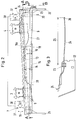
- the ribbon cassette is designed for both a serial and a line printer. It has a base plate 1 and an ink ribbon memory, which is formed by a first ink ribbon roll 2. On the base plate 1, which is open both at the top and at the bottom, two spool axles 3 and 4, which can be driven in rotation, are rotatably mounted on the base plate 1 standing at a distance adapted to the size of the device. The first ribbon roll 2 and a second ribbon roll 5 can be plugged onto these spool axes 3 and 4. Each coil axis 3 and 4 is assigned a ribbon guide element on the side in order to guide an ink ribbon 6. There is a first ribbon guide element 7 on the outside of the ribbon roll 2 and a second ribbon guide element 8 on the ribbon roll 5.
- Drive motors 9 can consist of stepper motors.
- the drive motors 9 can be actuated by means of a control circuit 10.
- the control circuit 10 also includes a controller 11 for the detection of the beginning or end of the ribbon, so that speed, cycle times, tension and the like can be regulated.
- the control circuit 10 is arranged as an integrated circuit 12 (with a microprocessor) on a printed circuit board 13.
- the circuit board 13 is located on the underside 1a of the base plate 1. As can be seen below, this arrangement of the circuit board 13 next to the drive motors 9 is not only very advantageous in terms of line technology, but also in terms of an easily accessible protective space.
- the base plate 1 is at an angle 14 (FIG. 2) to a mounting plate 15.
- the printing elements for example printing wires, printing needles, electrodes and the like
- a pressure path 17 results in the angle 14 (FIG. 1).
- Pairs of projections 18 with a height 19 corresponding to the course of the base plate 1 to the mounting plate 15 are arranged on the mounting plate 15.
- Corresponding counter-projections 18a protrude on the base plate 1 in order to determine the angle 14.
- Screws 20 extend through the projections 18, 18a in order to releasably connect the two plates.
- the entire unit of base plate 1 and mounting plate 15 is inserted into the respective printer via side walls 21 and 22 and locked there accordingly.
- a cable 24 is provided with a length 25 for a plug connection 26 in order to introduce the entire energy supply of the ribbon cassette from the printer.
- the cable 24 is then guided to the circuit board 13 and also transmits the power supply or the control energy for the drive motors 9 through further cables 27 and 28, starting from the circuit board 13.
- the ribbon guide elements 7 and 8 are fastened to the base plate 1 by means of screws 29 and 30.
- a bearing plate for the coil axes 3 and 4 is also connected by means of screws 31. Suitable supports 32 keep the bearing plate 13 isolated.
- the spool axles 3 and 4 are also each provided with pivotable locking arms 35 for the storage and attachment of the ribbon rolls 2 and 5.
- the ribbon guide elements 7 and 8 form sliding surfaces 36 and guide cuts 37, which are arranged on special shaped bodies 38.
Landscapes
- Impression-Transfer Materials And Handling Thereof (AREA)
Applications Claiming Priority (2)
| Application Number | Priority Date | Filing Date | Title |
|---|---|---|---|
| DE4041991 | 1990-12-21 | ||
| DE4041991A DE4041991C2 (de) | 1990-12-21 | 1990-12-21 | Farbbandvorrichtung, insbesondere für einen Zeilendrucker |
Publications (2)
| Publication Number | Publication Date |
|---|---|
| EP0492755A2 true EP0492755A2 (fr) | 1992-07-01 |
| EP0492755A3 EP0492755A3 (en) | 1993-02-24 |
Family
ID=6421563
Family Applications (1)
| Application Number | Title | Priority Date | Filing Date |
|---|---|---|---|
| EP19910250328 Withdrawn EP0492755A3 (en) | 1990-12-21 | 1991-12-09 | Ink ribbon cassette, particularly for line printers |
Country Status (3)
| Country | Link |
|---|---|
| US (1) | US5228789A (fr) |
| EP (1) | EP0492755A3 (fr) |
| DE (1) | DE4041991C2 (fr) |
Families Citing this family (2)
| Publication number | Priority date | Publication date | Assignee | Title |
|---|---|---|---|---|
| DE4332608C2 (de) * | 1993-09-24 | 2003-01-09 | Meto International Gmbh | Kassette |
| US6056454A (en) | 1998-10-05 | 2000-05-02 | Gerber Technology, Inc. | Method and apparatus for printing on a continuously moving sheet of work material |
Family Cites Families (15)
| Publication number | Priority date | Publication date | Assignee | Title |
|---|---|---|---|---|
| DE2163469A1 (de) * | 1971-12-21 | 1973-07-05 | Anker Werke Ag | Farbbandtransporteinrichtung an druckenden bueromaschinen oder dergl |
| FR2359775B1 (fr) * | 1976-07-26 | 1985-09-27 | Printronix Inc | Dispositif d'entrainement de ruban |
| JPS54100808A (en) * | 1978-01-25 | 1979-08-08 | Suwa Seikosha Kk | Printer |
| US4313683A (en) * | 1979-10-19 | 1982-02-02 | International Business Machines Corporation | Microcomputer control of ribbon drive for printers |
| US4402621A (en) * | 1981-09-25 | 1983-09-06 | International Business Machines Corp. | Ribbon cartridge with ribbon guide arms |
| JPS59187885A (ja) * | 1983-04-08 | 1984-10-25 | Fujitsu Ltd | インクリボン送り速度制御方式 |
| DE8408998U1 (de) * | 1984-03-23 | 1984-06-14 | Kienzle Apparate Gmbh, 7730 Villingen-Schwenningen | Spanneinrichtung fuer ein in einer kassette angeordnetes farbband |
| ATE36138T1 (de) * | 1984-09-18 | 1988-08-15 | Mannesmann Tally Gmbh | Farbbandeinrichtung mit einer farbbandaufnahme fuer drucker, insbesondere fuer matrixzeilendrucker. |
| JPH0143267Y2 (fr) * | 1984-11-20 | 1989-12-15 | ||
| JPS61258783A (ja) * | 1985-05-13 | 1986-11-17 | Nec Corp | 熱転写式シリアル・プリンタ |
| JPS6359583A (ja) * | 1986-08-29 | 1988-03-15 | Toshiba Corp | 印字装置およびこの装置に使用するインクリボンカ−トリツジ |
| US4801215A (en) * | 1987-05-28 | 1989-01-31 | Pelikan, Inc. | Ramp ribbon cartridge |
| US5039237A (en) * | 1987-06-02 | 1991-08-13 | Oki Electric Industry Co., Ltd. | Dot matrix print head drive method |
| US4826334A (en) * | 1987-09-25 | 1989-05-02 | Surti Tyrone N | Endless loop ribbon cassette with ordered storage |
| DE3742238A1 (de) * | 1987-12-12 | 1989-06-22 | Philips Patentverwaltung | Drucker mit einer austauschbar einlegbaren farbbandkassette |
-
1990
- 1990-12-21 DE DE4041991A patent/DE4041991C2/de not_active Expired - Fee Related
-
1991
- 1991-12-09 EP EP19910250328 patent/EP0492755A3/de not_active Withdrawn
- 1991-12-23 US US07/813,146 patent/US5228789A/en not_active Expired - Fee Related
Also Published As
| Publication number | Publication date |
|---|---|
| EP0492755A3 (en) | 1993-02-24 |
| US5228789A (en) | 1993-07-20 |
| DE4041991A1 (de) | 1992-07-02 |
| DE4041991C2 (de) | 1994-06-30 |
Similar Documents
| Publication | Publication Date | Title |
|---|---|---|
| DE3702270C2 (fr) | ||
| DE69008497T2 (de) | Drucker mit Einrichtung zum Beseitigen von Papierstau. | |
| EP0195949B1 (fr) | Imprimante à un ou plusieurs postes d'impression | |
| DE3725334A1 (de) | Punktdrucker | |
| EP0297025B1 (fr) | Dispositif d'enregistrement à partir d'un écran sur un support d'informations | |
| DE2345466B2 (de) | Farbbandkassette zur Verwendung bei Nadeldruckwerken | |
| DE69824248T2 (de) | Tintenstrahldrucker und Verfahren zum beidseitigen Bedrucken von Etikettenbahnen | |
| EP0019649B1 (fr) | Mécanisme et cassette pour des rubans encreurs | |
| DE2951610C2 (de) | Farbbandkassette für eine Schreib- o.ä. Büromaschine | |
| DE2644049C3 (de) | Drucker mit mehreren in Zeilenrichtung nebeneinander angeordneten Druckköpfen | |
| DE3844693C2 (fr) | ||
| DE3014286C2 (de) | Druckvorrichtung mit einer motorgetriebenen Typenscheibe | |
| EP0149964A1 (fr) | Cartouche de ruban encreur | |
| DE3685547T2 (de) | Abdeckanordnung fuer frankiermaschine. | |
| EP0492755A2 (fr) | Cassette à ruban encreur pour en particulier imprimantes par ligne | |
| DE3722226A1 (de) | Farbbandkassette fuer schreib- oder aehnliche bueromaschinen | |
| DE69735904T2 (de) | Banddruckgerät und Bandbehälter | |
| DE3685549T2 (de) | Aus modulen aufgebaute universelle frankiermaschine. | |
| DE3545912C2 (de) | Drucker | |
| EP0281500B1 (fr) | Imprimante matricielle | |
| DE2921799A1 (de) | Vorschubvorrichtung fuer das aufzeichnungsmaterial eines druckers | |
| EP0264595A2 (fr) | Dispositif d'enregistrément pour machine à écrire ou machine de bureau similaire | |
| EP1206355A1 (fr) | Imprimante comportant deux stations d'impression | |
| DE3685548T2 (de) | Schrittmotormodul fuer frankiermaschine. | |
| DE3670796C5 (de) | Drucker mit einer oder mehreren Druckstationen. |
Legal Events
| Date | Code | Title | Description |
|---|---|---|---|
| PUAI | Public reference made under article 153(3) epc to a published international application that has entered the european phase |
Free format text: ORIGINAL CODE: 0009012 |
|
| AK | Designated contracting states |
Kind code of ref document: A2 Designated state(s): AT DK ES FR GB IT NL SE |
|
| PUAL | Search report despatched |
Free format text: ORIGINAL CODE: 0009013 |
|
| AK | Designated contracting states |
Kind code of ref document: A3 Designated state(s): AT DK ES FR GB IT NL SE |
|
| 17P | Request for examination filed |
Effective date: 19930721 |
|
| 17Q | First examination report despatched |
Effective date: 19941228 |
|
| STAA | Information on the status of an ep patent application or granted ep patent |
Free format text: STATUS: THE APPLICATION IS DEEMED TO BE WITHDRAWN |
|
| 18D | Application deemed to be withdrawn |
Effective date: 19951222 |