EP0493080A2 - Adaptateur d'alimentation enfichable - Google Patents
Adaptateur d'alimentation enfichable Download PDFInfo
- Publication number
- EP0493080A2 EP0493080A2 EP91311968A EP91311968A EP0493080A2 EP 0493080 A2 EP0493080 A2 EP 0493080A2 EP 91311968 A EP91311968 A EP 91311968A EP 91311968 A EP91311968 A EP 91311968A EP 0493080 A2 EP0493080 A2 EP 0493080A2
- Authority
- EP
- European Patent Office
- Prior art keywords
- adapter
- case
- power supply
- plug
- transformer
- Prior art date
- Legal status (The legal status is an assumption and is not a legal conclusion. Google has not performed a legal analysis and makes no representation as to the accuracy of the status listed.)
- Ceased
Links
Images


Classifications
-
- H—ELECTRICITY
- H01—ELECTRIC ELEMENTS
- H01R—ELECTRICALLY-CONDUCTIVE CONNECTIONS; STRUCTURAL ASSOCIATIONS OF A PLURALITY OF MUTUALLY-INSULATED ELECTRICAL CONNECTING ELEMENTS; COUPLING DEVICES; CURRENT COLLECTORS
- H01R13/00—Details of coupling devices of the kinds covered by groups H01R12/70 or H01R24/00 - H01R33/00
- H01R13/66—Structural association with built-in electrical component
- H01R13/665—Structural association with built-in electrical component with built-in electronic circuit
- H01R13/6675—Structural association with built-in electrical component with built-in electronic circuit with built-in power supply
Definitions
- This invention relates to an AC adapter of the type used to provide a DC voltage to an associated electronic instrument from an AC supply voltage.
- the invention is particularly designed for use with electronic instruments in a medical environment.
- Modern medical treatment facilities employ a variety of sophisticated electronic instruments in the course of patient diagnosis and treatment.
- electronically operated medication infusion pumps are commonly used for administering one or more selected medical fluids to a patient at a prescribed flow rate and time schedule.
- Such fluid medication infusion pumps and other electronic equipment require a source of electrical power to maintain the instrument in a desired operational state.
- the AC adapter frequently comprises a power supply adapter designed for direct plug-in connection to an AC power supply outlet, with a cord extending between the plug-in adapter and associated electronic instrument, to supply DC to the instrument.
- plug-in power supply adapters have included a relatively compact housing or case having the components of an AC adapter mounted therein.
- Conductive prongs associates with the transformer components have protruded from the adapter case for plug-in connection in the manner of a standard electrical plug with an associated AC power supply receptacle, such as one socket of a standard double or multi-point wall outlet, or a multisocket strip, or the like.
- the adapter case essentially comprises the body of an electrical plug for manual grasping in the course of plug-in and unplugging movements.
- the physical size and shape of the adapter case has typically exceeded the width and height of a conventional electrical plug, such that the adapter case partially overlies and therefore obstructs access to adjacent electrical sockets.
- plug-in connection of a single AC/DC power supply adapter to one of the electrical sockets normally obscures and thus precludes access to all of the remaining electrical sockets in the wall outlet. Additional electrical devices which may be desired or necessary, especially in a medical treatment facility must therefore be plugged into a different wall outlet.
- the adapter should preferably also include means for convenient and stable mounting in a stored position in association with an electrical instrument for transport purposes.
- a power supply adapter for plug-in connection to an electrical socket connected to an AC power supply
- the adapter comprising an adapter case having a plurality of conductive pins protruding from a first end for plug-in connection to the electrical socket and an AC adapter electrical assembly having a plurality of components mounted with the case characterised in that the said components are in an arrangement disposed generally in-line with the pins.
- the AC adapter electrical assembly includes a transformer mounted within the case generally adjacent the first end and preferably also at lest one filter capacitor and a rectifier.
- the mounting clip located on the case, the mounting clip preferably being formed integrally with the case.
- the case comprises a wider front portion and a narrow rear portion, the transformer being mounted within the front portion, and the mounting clip comprising a clip leg projecting rearwardly as a continuation at one side of the front portion but in spaced relation with the rear portion to define a rearwardly open slot.
- the clip leg comprises a ramped lock tooth at its inboard free end.
- the case is formed from two interfitting case members which together define a hollow interior in which this said plurality of components are located.
- a strain relief fitting connected between the power cord and the case.
- the case may be formed of a distal half and a proximal half and includes a strain relief located between the distal and proximal halves of the case.
- the strain relief fitting comprises an alternative sequence of relatively wide plate members and comparatively narrow neck members.
- the invention may comprise an adapter case formed from first and second interfitting case members co-operatively defining a hollow case interior, the case having a front end wall and a rear end wall; a plurality of conductive pins or prongs protruding from the front end wall of the case; an AC adapter electrical assembly having a plurality of components mounted within the case in an arrangement generally in-line with the prongs, the components including a transformer disposed generally adjacent to the front end wall; and a power cord coupled to the rear end wall of the case.
- the invention may be considered to provide a power supply adapter for plug-in connection to an electrical socket connected to an AC power supply
- the power supply adapter comprising: an adapter case having a distal end and a proximal opposite end; a plurality of conductive prongs protruding from the distal end of the case, the plurality of conductive prongs for plug-in connection to the electrical socket; a transformer located inside the adapter case near its distal end, the transformer being electrically connected to the conductive prongs; a filter capacitor and a rectifier electrically connected to the transformer, the filter capacitor and rectifier being located proximal to the transformer whereby the components mounted within the case are disposed in generally in-line fashion with the prongs; and a power cord electrically connected to the rectifier and mechanically connected to the proximal end of the case.
- the invention also extends to a method of making a power supply adapter for plug-in connection to an electrical socket connected to an AC power supply,the method comprising: supplying an adapter case having first and second opposite ends; mounting a plurality of conductive prongs in protruding fashion from the first end of the case for plug-in connection to the electrical socket; and installing a plurality of components within the case in an arrangement disposed generally in-line with the prongs.
- an improved power supply adapter for plug-in connection to a standard AC power supply receptacle to provide a DC voltage to an associated electronic instrument.
- the power supply adapter is designed with an AC adapter assembly mounted within a compact adapter case having an end face with conductive plug pins or prongs protruding therefrom.
- the components of the transformer assembly are arranged generally in-line between the conductive prongs and a power cord, so that the case can be constructed with a narrow width and low profile height to avoid obstructing the adjacent sockets of a standard multisocket wall outlet.
- the case of the power supply adapter preferably further includes means for the relatively simple removable mounting in a stored position on or in close association with the electronic instrument when the power supply adapter is not in use.
- the mounting means comprises a mounting clip formed integrally with the adapter case for secure yet removable mounting onto a bracket arm or some other support structure associated with the electronic instrument.
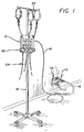
- an AC power adapter 10 is provided for use with an electronic instrument 12, such as a fluid medication infusion pump.
- the adapter 10 is designed for quick and easy plug-in connection to a standard AC power supply unit, and to provide a DC voltage via a power cord 16 to the electronic instrument 12.
- the adapter 10 is constructed with an elongated geometry having a relatively narrow width and low profile height, so that it does not obstruct or otherwise interfere with access to adjacent electrical sockets 17 of multisocket outlet 14.
- the power supply adapter 10 of the present invention may be used with a wide range of electrical and/or electronic instruments
- the illustrative drawings show the adapter 10 in a preferred environment of use, namely, in association with an electronic instrument 12 in a medical environment.
- the instrument 12 in Figure 1 is a fluid medication infusion pump, specifically the MiniMed III fluid infusion marketed by MiniMed Technologies of Sylmar.
- the infusion pump 12 is a relatively compact instrument adapted for mounting onto a conventional portable medical equipment pole 18 by means of an appropriate clamp fixture 20, such as the adjustable clamp fixture described in US Patent 4832299, which is incorporated by reference herein.
- the infusion pump 12 is shown to include multiple parallel pumping systems for independent programming and control to regulate the administration of multiple medical fluids from appropriate reservoirs 22 to the patient (not shown) via suitable tubing 24.
- the electronic control components and associated electronically powered pumping devices are integrated into the housing of the infusion pump 12.
- the infusion pump 12 is designed for normal operation by connection to an appropriate AC power supply outlet 14 by means of the AC adapter 10 and the power cord 16, with the AC adapter 10 supplying a selected DC voltage to the infusion pump 12.
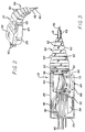
- the AC adapter 10 includes a relatively compact housing or case as defined by a lower base 28 and an upper cap 30.
- case components in the preferred form, are constructed from a relatively lightweight and high impact moulded plastics material, such as glass-filled nylon.
- the base 28 and cap 30 have a generally concave or shell-shaped configuration and together define a hollow case interior for receiving and supporting the components of an AC adapter electrical assembly 32.
- the AC adapter electrical assembly 32 includes a transformer 34 securely seated within the base 28 in a nested or cradled relation with respect to a plurality of short locator tabs 36.
- the transformer 34 is positioned in close proximity to a forward end wall 38 from which a plurality of conductive pins 40 protrude in a conventional three-pin array for plug-in connection to the AC outlet 14.
- these conductive prongs 40 are securely mounted near their rear ends within the end wall 38 by insert moulding or the like.
- the remaining components of the AC adapter electrical assembly 32 are mounted within the adapter case is generally in-line configuration with respect to the transformer 34 and the conductive prongs 40.
- Figures 3 and 4 shown these remaining components in the form of a filter capacitor 42 and a rectifier 44. All of these components are appropriately coupled electrically by means of suitable conductive wires 46.
- a selected trio of the wires 46 are assembled within a protective outer sheath 48 to define the power cord 16 connected to the associated electronic instrument 12. These conductive wires 46 are suitably collected for passage through a notch 50 formed in a rear end wall 52 of the base 28.
- a strain relief fitting 54 is mounted at the rear end wall 52, providing a flexible structural member connected between the base 28 and the power cord 16 to anchor the power cord 16 securely to the adapter 10.
- the strain relief fitting 54 has a mounting head plate 56 at one end for seated reception against the inboard side of the rear end wall 52 of the base 28, with a narrow neck 58 adjacent the head plate 56 and dimensional to fit closely in the open notch 50. From the neck 58, the strain relief fitting 54 includes an alternating sequence of plate and neck segments 60 and 62 which define a flexible structure to retain the associated end of the power cord 16 securely.
- strain relief fitting 54 is designed to permit and flexure (Figure 2) at the adapter case that may be required for use in close clearance locations. Moreover, the fitting 54 is designed to prevent or resist cord breakage at the adapter which may otherwise occur, for example, when the adapter is unplugged by pulling on the power cord 16.
- the adapter case is closed by mounting the cap 30 onto the base 28.
- the mounting may be achieved by snap-fit connections, ultrasonic welding, and/or adhesive, with a permanently closed adapter case construction being desired.
- the resultant AC adapter 10 includes the components of the AC adapter electrical assembly 32 in a substantially in-line arrangement between the conductive pins 40 and the power cord 16.
- the adapter 10 thus has an elongate shape which can be easily grasped and/or manipulated manually for plug-in connection to and unplugging from an AC power supply.
- the elongate AC adapter electrical assembly 32 also presents a relatively narrow width and a low profile height conforming generally with the dimensions of a standard electrical power plug, so that the plug-in connection of the AC adapter 10 to an electrical socket 17 (Figure 1) does not interfere with or otherwise obstruct access to adjacent electrical sockets 17 of a typical multi-point or strip outlet 17. As a result, the adjacent sockets 17 remain available for easy access and plug-in connection with other electronic instruments as may be necessary or desirable.
- the width and height of the adapter case are predominantly a function of the size and shape of the transformer 34.
- a compact transformer such as that available from ISL Products International, Ltd, of Syosset, New York, under model designation EI 41, it has been possible to construct an AC adapter 10 with a low profile height of about 1.5 to 1.6 inch (38.1 to 40.6mm) and a narrow width of about 1.7 to 1.8 inch (43.2 to 45.7mm).
- the assembled adapter case defines a rearwardly projecting mounting clip 64 for convenient removable mounting of the AC adapter 10 in a stored position with respect to the associated electronic instrument 12.
- the clip 64 is shown in the form of a rearwardly projecting clip leg 66 formed integrally with the base 28 and cap 30 at one side of the case.
- the clip leg 66 is formed as a continuation of a wider frontal portion of the case within which the transformer core 34 of the case within which the transformer core 34 is mounted, but in spaced relation with a narrower rear case portion which houses the filter capacitor 42 therein.
- the clip leg 66 co-operates with the narrow rear portion of the case to define a rearwardly open slot 68 dimensioned to receive a bracket arm 70 of the clamp fixture 20, as shown in Figure 5. That is, the clip 64 permits the adapter 10 to be removably mounted quickly and easily onto the bracket arm 70 in close stored association with the medical instrument 12.
- a lock tooth 72 at the inboard free end of the clip leg 66 includes tapered leading and trailing edges for facilitating secure clip-on mounting and subsequent removal of the adapter 10 from the bracket arm 70.
- a support strap 74 having loop and hook Velcro-type fasteners may be mounted on the bracket arm 70 for releasably supporting the power cord 16 in a coiled or other suitably compact configuration.
- the modified adapter 10′ includes a transformer 34′ mounted within a compact case in in-line relation with a plurality of conductive plug pins 40′.
- the remaining components of the AC adapter 10′ include one or more filter capacitors 42′ and a rectifier 44′, which are inserted moulded within a separate case portion 78 spaced rearwardly from the transformer 34′.
- a strain relief fitting 54′ is positioned between the transformer 34′ and the capacitors 42′ and rectifier 44′, with all of the components again positioned in a generally in-line configuration between the pins 40′ and the power cord 16′.
Landscapes
- Engineering & Computer Science (AREA)
- Microelectronics & Electronic Packaging (AREA)
- Details Of Connecting Devices For Male And Female Coupling (AREA)
- Manufacturing Of Electrical Connectors (AREA)
- Rectifiers (AREA)
Applications Claiming Priority (2)
| Application Number | Priority Date | Filing Date | Title |
|---|---|---|---|
| US63590590A | 1990-12-27 | 1990-12-27 | |
| US635905 | 1990-12-27 |
Publications (2)
| Publication Number | Publication Date |
|---|---|
| EP0493080A2 true EP0493080A2 (fr) | 1992-07-01 |
| EP0493080A3 EP0493080A3 (en) | 1992-10-07 |
Family
ID=24549597
Family Applications (1)
| Application Number | Title | Priority Date | Filing Date |
|---|---|---|---|
| EP19910311968 Ceased EP0493080A3 (en) | 1990-12-27 | 1991-12-23 | Plug-in power supply adapter |
Country Status (3)
| Country | Link |
|---|---|
| EP (1) | EP0493080A3 (fr) |
| JP (1) | JP3288415B2 (fr) |
| CA (1) | CA2055079A1 (fr) |
Cited By (7)
| Publication number | Priority date | Publication date | Assignee | Title |
|---|---|---|---|---|
| WO1995033288A1 (fr) * | 1994-05-26 | 1995-12-07 | Vattenfall Ab | Prise murale |
| AT401701B (de) * | 1993-08-18 | 1996-11-25 | Egston Eggenburger Syst Elektr | Netzgerät für einen elektrischen kleinverbraucher |
| AT401836B (de) * | 1992-09-04 | 1996-12-27 | Egston Eggenburger Syst Elektr | Netzgerät für einen elektrischen kleinverbraucher |
| WO2003094305A1 (fr) * | 2002-05-01 | 2003-11-13 | Microlead Technoloy Ltd. | Bloc d'alimentation |
| CN100426598C (zh) * | 2005-01-12 | 2008-10-15 | 泰尼普拉科技(深圳)有限公司 | 新型插头式电源装置 |
| US9425566B2 (en) | 2014-02-19 | 2016-08-23 | Powertech Industrial Co., Ltd. | Power strip and cord thereof |
| CN112202007A (zh) * | 2020-09-25 | 2021-01-08 | 程昌锋 | 一种自动收卷电源线的插排 |
Family Cites Families (5)
| Publication number | Priority date | Publication date | Assignee | Title |
|---|---|---|---|---|
| FR902735A (fr) * | 1944-03-15 | 1945-09-11 | Prise de courant transformateur de tension | |
| FR1347470A (fr) * | 1963-02-12 | 1963-12-27 | Formes suspensives pour appareils électriques | |
| DE1640717B2 (de) * | 1967-08-22 | 1971-12-02 | Kabel und Metallwerke Gutehoff nungshutte AG, 3000 Hannover | Knickschutzeinrichtung fuer elektrische leitungen umschliessen de stecker buchsenkupplungen oder dergl |
| BE722501A (fr) * | 1968-03-12 | 1969-04-01 | ||
| US4273406A (en) * | 1978-12-28 | 1981-06-16 | Mitsuoka Electric Mfg. Co., Ltd. | Electrical cord adapter |
-
1991
- 1991-11-06 CA CA 2055079 patent/CA2055079A1/fr not_active Abandoned
- 1991-12-23 EP EP19910311968 patent/EP0493080A3/en not_active Ceased
- 1991-12-27 JP JP34629791A patent/JP3288415B2/ja not_active Expired - Lifetime
Cited By (9)
| Publication number | Priority date | Publication date | Assignee | Title |
|---|---|---|---|---|
| AT401836B (de) * | 1992-09-04 | 1996-12-27 | Egston Eggenburger Syst Elektr | Netzgerät für einen elektrischen kleinverbraucher |
| AT401701B (de) * | 1993-08-18 | 1996-11-25 | Egston Eggenburger Syst Elektr | Netzgerät für einen elektrischen kleinverbraucher |
| WO1995033288A1 (fr) * | 1994-05-26 | 1995-12-07 | Vattenfall Ab | Prise murale |
| US5751542A (en) * | 1994-05-26 | 1998-05-12 | Vattenfall Ab | Wall socket |
| WO2003094305A1 (fr) * | 2002-05-01 | 2003-11-13 | Microlead Technoloy Ltd. | Bloc d'alimentation |
| US7259975B2 (en) | 2002-05-01 | 2007-08-21 | Microlead Technology Ltd. | Power supply unit |
| CN100426598C (zh) * | 2005-01-12 | 2008-10-15 | 泰尼普拉科技(深圳)有限公司 | 新型插头式电源装置 |
| US9425566B2 (en) | 2014-02-19 | 2016-08-23 | Powertech Industrial Co., Ltd. | Power strip and cord thereof |
| CN112202007A (zh) * | 2020-09-25 | 2021-01-08 | 程昌锋 | 一种自动收卷电源线的插排 |
Also Published As
| Publication number | Publication date |
|---|---|
| JP3288415B2 (ja) | 2002-06-04 |
| EP0493080A3 (en) | 1992-10-07 |
| CA2055079A1 (fr) | 1992-06-28 |
| JPH04296476A (ja) | 1992-10-20 |
Similar Documents
| Publication | Publication Date | Title |
|---|---|---|
| US5243510A (en) | Plug-in power supply adapter with components in the strain relief member | |
| US5176343A (en) | Electrical adapter plug clip | |
| US6352527B1 (en) | Surgical/medical irrigator with rechargeable battery pack | |
| US12329370B2 (en) | Illuminated surgical retractor | |
| JP4755376B2 (ja) | 医療装置用インタフェースシステム | |
| US4369487A (en) | Utility lamp | |
| JP3174572B2 (ja) | 蠕動輸液装置 | |
| US5575677A (en) | Electrical power plug retainer | |
| US5158528A (en) | Peristaltic infusion device and charger unit | |
| US7490837B2 (en) | Equipment caddie system | |
| US9486268B2 (en) | Battery pack attached to a cable | |
| JP2006326315A (ja) | 医療器具用の柔軟固定装置 | |
| EP0493080A2 (fr) | Adaptateur d'alimentation enfichable | |
| US10737007B2 (en) | Patient adapter for driveline cable and methods | |
| EP0647107A1 (fr) | Support pour systeme de perfusion intraveineuse | |
| CA2260772A1 (fr) | Irrigateur chirurgical alimente par batterie | |
| CA2345172A1 (fr) | Pompe a perfusion | |
| WO2007117638A2 (fr) | Prise de courant à cordon rétractable pouvant être reliée à une potence pour intraveineuse | |
| CN212090408U (zh) | 用于液体输注泵的保持装置以及包括其的液体输注设备 | |
| US20230371702A1 (en) | Headboard pouch | |
| TW201936218A (zh) | 真空產生裝置 | |
| US6216042B1 (en) | Pacemaker wire holder | |
| CN215194669U (zh) | 一种急救式呼吸机 | |
| CN211884832U (zh) | 一种方便使用的雾化装置 | |
| WO2021178829A1 (fr) | Système de fixation pour fixer des dispositifs médicaux à des structures de support |
Legal Events
| Date | Code | Title | Description |
|---|---|---|---|
| PUAI | Public reference made under article 153(3) epc to a published international application that has entered the european phase |
Free format text: ORIGINAL CODE: 0009012 |
|
| AK | Designated contracting states |
Kind code of ref document: A2 Designated state(s): DE FR GB IT NL SE |
|
| PUAL | Search report despatched |
Free format text: ORIGINAL CODE: 0009013 |
|
| AK | Designated contracting states |
Kind code of ref document: A3 Designated state(s): DE FR GB IT NL SE |
|
| 17P | Request for examination filed |
Effective date: 19930406 |
|
| 17Q | First examination report despatched |
Effective date: 19940502 |
|
| RAP1 | Party data changed (applicant data changed or rights of an application transferred) |
Owner name: IVAC CORPORATION |
|
| STAA | Information on the status of an ep patent application or granted ep patent |
Free format text: STATUS: THE APPLICATION HAS BEEN REFUSED |
|
| 18R | Application refused |
Effective date: 19960101 |
|
| RAP1 | Party data changed (applicant data changed or rights of an application transferred) |
Owner name: IVAC MEDICAL SYSTEMS, INC. |
|
| RAP1 | Party data changed (applicant data changed or rights of an application transferred) |
Owner name: IVAC MEDICAL SYSTEMS, INC. |