EP0493261A2 - Objectif varifocal - Google Patents
Objectif varifocal Download PDFInfo
- Publication number
- EP0493261A2 EP0493261A2 EP91403548A EP91403548A EP0493261A2 EP 0493261 A2 EP0493261 A2 EP 0493261A2 EP 91403548 A EP91403548 A EP 91403548A EP 91403548 A EP91403548 A EP 91403548A EP 0493261 A2 EP0493261 A2 EP 0493261A2
- Authority
- EP
- European Patent Office
- Prior art keywords
- lens
- positive
- lens group
- negative
- zoom lens
- Prior art date
- Legal status (The legal status is an assumption and is not a legal conclusion. Google has not performed a legal analysis and makes no representation as to the accuracy of the status listed.)
- Granted
Links
Images


Classifications
-
- G—PHYSICS
- G02—OPTICS
- G02B—OPTICAL ELEMENTS, SYSTEMS OR APPARATUS
- G02B15/00—Optical objectives with means for varying the magnification
- G02B15/14—Optical objectives with means for varying the magnification by axial movement of one or more lenses or groups of lenses relative to the image plane for continuously varying the equivalent focal length of the objective
- G02B15/144—Optical objectives with means for varying the magnification by axial movement of one or more lenses or groups of lenses relative to the image plane for continuously varying the equivalent focal length of the objective having four groups only
- G02B15/1441—Optical objectives with means for varying the magnification by axial movement of one or more lenses or groups of lenses relative to the image plane for continuously varying the equivalent focal length of the objective having four groups only the first group being positive
- G02B15/144113—Optical objectives with means for varying the magnification by axial movement of one or more lenses or groups of lenses relative to the image plane for continuously varying the equivalent focal length of the objective having four groups only the first group being positive arranged +-++
-
- G—PHYSICS
- G02—OPTICS
- G02B—OPTICAL ELEMENTS, SYSTEMS OR APPARATUS
- G02B15/00—Optical objectives with means for varying the magnification
- G02B15/14—Optical objectives with means for varying the magnification by axial movement of one or more lenses or groups of lenses relative to the image plane for continuously varying the equivalent focal length of the objective
- G02B15/22—Optical objectives with means for varying the magnification by axial movement of one or more lenses or groups of lenses relative to the image plane for continuously varying the equivalent focal length of the objective with movable lens means specially adapted for focusing at close distances
Definitions
- the present invention generally relates to zoom lenses and, more particularly, is directed to a zoom lens for use with electronic still cameras, video cameras or the like, for example.
- consumer video cameras employ a lens having a zooming ratio of 6 times or more and whose F number is smaller than 2.0 as a zoom lens. Recently, it has been requested that the video camera be still further miniaturized and reduced in weight while maintaining the features such that the zoom lens has a large variable magnification and has also a large brightness.
- the imager size of a charge-coupled device (CCD) image pickup device utilized as the image pickup element should be more miniaturized because it is to be noted from a scaling law standpoint that a camera lens itself can be miniaturized in accordance with the reduction of the imager size.
- CCD charge-coupled device
- the conventional zoom lens comprises 10 spherical lenses or more. There is then the disadvantage that a conventional lens cannot be miniaturized and reduced in weight sufficiently. Further, when the camera lens is miniaturized from a scaling law standpoint, then precision prescribed of each of the lenses constructing the zoom lens also is increased so that, if the number of the lenses constructing the zoom lens remains the same, then the zoom lens cannot be processed without difficulty. Particularly, when a lens element is finished as a spherical surface by the polishing-treatment, if the radius of curvature of the spherical surface is reduced, there is then the risk that a manufacturing cost for achieving the precision prescribed is increased considerably.
- the lens surface can be formed as an aspherical surface with ease and the number of lens elements constructing the camera lens can be reduced, which can make a great contribution to the camera lens when the camera lens is miniaturized and reduced in weight.
- Another object of the present invention is to provide a zoom lens which can be reduced in weight while maintaining the characteristics such that the variable magnification thereof is large and that the F number thereof is small.
- a further object of the present invention is to provide a zoom lens whose full length can be reduced.
- Still another object of the present invention is to provide a zoom lens in which bad influences such as ghost or the like can be reduced.
- a zoom lens in which a fixed first lens group having a positive refracting power, a second lens group having a negative refracting power and which realizes a variable magnification, a fixed third lens group having a positive refracting power and a fourth lens group having a positive refracting power which compensates fluctuation of an image surface caused by the variable magnification and which focuses an image are sequentially provided from an object side.
- the third lens group is composed of two separate lenses of a positive lens and a negative lens. At least one surface of the positive lens is formed as an aspherical surface and a surface of the negative lens opposing the image surface side is concaved to the image surface side.
- the present invention is directed to a zoom lens in which a fixed first lens group 1 having a positive refracting power, a second lens group 2 having a negative refracting power and which realizes a variable magnification, a fixed third lens group 3 having a positive refracting power and a fourth lens group 4 having a positive refracting power which compensates fluctuation of an image surface caused by the variable magnification and which focuses an image are sequentially provided from an object side.
- the third lens group 3 is composed of two separate lenses comprising a positive lens 31 and a negative lens 32.
- the shape of the surface 31a of the positive lens 31 opposing the object side is expressed by the following equation (4):
- Z Y2/R31 1 + 1 - (K31+1)Y2/R312 + (AD31)Y4 + (AE31)Y6 + (AF31)Y8 + (AG31)Y1 0
- Y represents the height from the optical axis
- Z represents the distance of lens apex from the tangential surface in a point on the aspherical surface in the height Y from the optical axis where the object side is assumed to be negative
- R31 represents the paraxial radius of curvature
- K31, AD31, AE31, AF31 and AG31 respectively represent coefficients .
- Y represents the height from the optical axis
- Z represents the distance of lens apex from the tangential surface in a point on the aspherical surface in the height Y from the optical axis where the object side is assumed to be negative
- R32 represents the paraxial radius of curvature
- K32, AD32, AE32, AF32 and AG32 respectively represent coefficients.
- the shape of the positive lens 31 satisfies the following relation expressed by the equation (6) below: -K31/(8R313) - AD31 + K32/(8R323) + AD32 > 0
- R34 (corresponding to R13) represents the radius of curvature of the surface of the negative lens 32, the positive lens 31 being convexed to the object side
- fw represents the focal length of the wide angle lens end of the zoom lens on the whole
- ft represents the vocal length of the telephoto lens end of the zoom lens on the whole
- the present invention employs as a fundamental arrangement a zoom lens of a rear-focus system formed of four lens groups of positive, negative, positive and positive lens groups composed of a fixed first lens group 1 having a positive refracting power, a second lens group 2 having a negative refracting power as a variator, a fixed third lens group 3 having a positive refracting power and a fourth lens group 4 having a positive refracting power which includes both a compensator function for correcting a movement of an image surface by the variable magnification of the second lens group so as to keep the image surface position constant and a focusing function.
- the zoom lens of the present invention is of the telephoto lens type in which the third lens group 3 is formed of separate positive lens and negative lens 32 provided from the object side, a principal point position of the third lens group 3 is provided near the object side.
- the movable range of the second lens group 2 can be extended effectively and the full length of the zoom lens can be reduced.
- the zoom lens of the present invention is of the telephoto lens type, a bundle of light incident on the fourth lens group 4 can be made smaller than that on the third lens group 3 and therefore the four lens groups 4 can be reduced in weight.
- the burden on the four lens group driving system can be reduced, the responsiveness to the magnification and focusing can be improved and a lens barrel structure including the lenses and the driving system can be reduced in diameter.
- the third lens group 3 is comprised of two lenses, the number of the lenses in the zoom lens can be reduced on the whole and the entirety of the zoom lens can be made more compact.
- the shapes of one surface 31a and the other surface 31b of the positive lens 31 are respectively expressed by the above equations (4) and (5) and the relationship expressed by the equation (6) is also established, which means that at least one surface of the positive lens 31 is formed as the aspherical surface.
- an aspherical surface acts as spherical aberration so that, by the combination of the positive lens 31 and the negative lens 32 within the third lens group 3, the correction of chromatic aberration on the axis which is the same aberration on the axis can be carried out independently of the correction of the spherical aberration. Accordingly, there is more freedom in the aberration correction of the third lens group 3.
- the front three lens groups of the first to third lens groups 1 to 3 constitute an afocal system. That is, a bundle of light from the third lens group 3 becomes a parallel bundle of light.
- the surface of the negative lens 32 in the third lens group 3 opposing the image side is shaped as substantially plane, then a re-focusing point of a reflected light from a target screen is formed near the target screen, causing a deterioration of image quality such as ghost or the like.
- the re-focusing point is formed at the rear side of the target screen as viewed from the object side.
- the fourth lens group 4 is moved toward the object side in the wide angle lens mode, the above re-focusing point is moved near the focal point or a bundle of light converged is passed through the target screen so that problems such as ghost or the like occur.
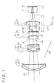
- FIG. 1 shows a zoom lens according to the embodiment of the present invention.
- a fixed first lens group 1 having a positive refracting power a fixed first lens group 1 having a positive refracting power
- a second lens group 2 having a negative refracting power as a variator a fixed third lens group 3 having a positive refracting power
- a fourth lens group 4 having a positive refracting power as a compensator are provided in that order from the object side to an image surface 5.
- the zoom lens of this embodiment is composed of four lens groups of positive, negative, positive and positive lenses and is formed as a rear-focus system which belongs, for example, to a so-called inner-focus system.
- an iris 6 is provided between the second lens group 2 and the third lens group 3, and a glass block 7 is provided between the fourth lens group 4 and the image surface 5 as an optical low-pass filter.
- the first lens group 1 is comprised of a negative meniscus lens 11 whose convex surface is opposed to the object side and a positive lens 12 bonded to the negative meniscus lens 11.
- the second lens group 2 is comprised of a negative meniscus lens 21 whose convex surface is opposed to the object side and a positive lens 23 bonded to the negative meniscus lens 21.
- the third lens group 3 is comprised of two separated lenses of a positive lens 31 and a negative lens 32 from the object side.
- the fourth lens 4 is comprised of a negative meniscus lens 41 whose convex surface is opposed to the object side and a positive lens 42 bonded to the meniscus lens 41.
- Both surfaces of the positive lens 31 of the third lens group 3 are formed as aspherical surfaces, and the iris 6 is located just in front of the positive lens 31 in an opposing relation to the object side.
- FIG. 2 shows the allocation of shape parameters of respective elements in the zoom lens according to this embodiment.
- ni and vi represents the refractive index of d line of medium between the i'th surface and (i + 1)'th surface and Abbe number, respectively.
- third, tenth, eleventh and sixteenth surfaces are formed of aspherical surfaces, respectively and the shape of the aspherical surface can be expressed by the following equation (8):
- Z Y2/Ri 1 + 1 - (Ki+1)Y2/ Ri2 + (ADi)Y4 + (AEi)Y6 + (AFi)Y8 + (AGi)Y1 0
- Y represents the height from the optical axis
- Z represents the distance of lens apex from the tangential surface in a point on the aspherical surface in the height Y from the optical axis
- Ki represents the constant of the cone of the i'th surface
- ADi, AEi, AFi and AGi represent aspherical surface constants of the i'th surface, respectively.
- the 10'th surface and the 11'th surface are respectively the surfaces of the positive lens 31 of the third lens group 3 in an opposing relation to the object side and the image surface side and a condition expressed by the following equation (9) is imposed between the above two surfaces: -K10/(8R103) - AD10 + K11/(8R113) + AD11 > 0
- the whole focal length f of the zoom lens according to this embodiment lies in a range of from 10 to 60 mm
- F number lies in a range of from 2.0 to 2.8
- a semi field angle w lies in a range of from 23.20 to 4.09°.
- the focal length ft on the telephoto lens side becomes 60 mm
- the focal length fw on the wide angle lens side becomes 10 mm.
- the first to third lens groups constitute an afocal system so that, when a light bundle qul incident on the first lens group 1 is a parallel light bundle (particularly a light bundle emitted from one point of the object located in the distant position can be regarded as a parallel light bundle in front of the lens), a light bundle ⁇ 2 emitted from the third lens group 3 to the fourth lens group 4 becomes close to a parallel light bundle.
- This parallel light bundle ⁇ 2 is converged at one point on the image surface 5 through the fourth lens group 4.
- a reflected light from the image surface 5 is returned through an opposite optical path to the negative lens 32 as a parallel light bundle ⁇ 3 so that, if the surface of the negative lens opposing the image surface 5 side is formed with a shape. substantially equal to the plane, then a ghost or the like is produced on the image surface 5 by the reflected light of the negative lens 32.
- the radius of curvature R13 of the surface of the negative lens 32 opposing the image surface 5 side must satisfy the condition expressed by the following equation (10): 0 ⁇ R13 ⁇ 6 fw ⁇ ft where the sign of the radius of curvature is determined so as to become a positive value when the lens surface becomes convexed to the object side.
- the above equation (10) means that LF ⁇ LI is established when the surface of the negative lens 32 opposing the image surface side becomes convexed relative to the image surface 5 side,LF represents the distance to a point at which a light bundle ⁇ 4 is converged from the negative lens 32 and the distance LI represents the distance between the negative lens 32 and the image surface 5. Accordingly, a weak reflected light, which is gradually diffused, is irradiated on the image surface 5 and the influence of ghost or the like can be reduced.
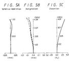
- FIGS. 3A to 3C, FIGS. 4A to 4C and FIGS. 5A to 5C respectively show various aberrations of the zoom lens according to this embodiment.
- the zoom lens of the present invention in the zoom lens formed of four lens groups of positive, negative, positive and positive lenses, since the third lens component is composed of two lenses of positive and negative lenses having aspherical surfaces, there is then the advantage that the zoom lens can be miniaturized and reduced in weight while maintaining the characteristics such that the variable magnification ratio is large and that the F number is small. Further, when the surface of the negative lens opposing the image surface side is convexed to the image surface side, then bad influence such as ghost or the like due to the reflected light from the negative lens can be reduced.
Landscapes
- Physics & Mathematics (AREA)
- General Physics & Mathematics (AREA)
- Optics & Photonics (AREA)
- Lenses (AREA)
Applications Claiming Priority (2)
| Application Number | Priority Date | Filing Date | Title |
|---|---|---|---|
| JP417122/90 | 1990-12-28 | ||
| JP2417122A JP3003226B2 (ja) | 1990-12-28 | 1990-12-28 | ズームレンズ |
Publications (3)
| Publication Number | Publication Date |
|---|---|
| EP0493261A2 true EP0493261A2 (fr) | 1992-07-01 |
| EP0493261A3 EP0493261A3 (en) | 1992-11-04 |
| EP0493261B1 EP0493261B1 (fr) | 1995-02-22 |
Family
ID=18525256
Family Applications (1)
| Application Number | Title | Priority Date | Filing Date |
|---|---|---|---|
| EP91403548A Expired - Lifetime EP0493261B1 (fr) | 1990-12-28 | 1991-12-26 | Objectif varifocal |
Country Status (5)
| Country | Link |
|---|---|
| US (1) | US5233471A (fr) |
| EP (1) | EP0493261B1 (fr) |
| JP (1) | JP3003226B2 (fr) |
| KR (1) | KR100195316B1 (fr) |
| DE (1) | DE69107600T2 (fr) |
Cited By (2)
| Publication number | Priority date | Publication date | Assignee | Title |
|---|---|---|---|---|
| EP0628844A1 (fr) * | 1993-06-07 | 1994-12-14 | Matsushita Electric Industrial Co., Ltd. | Objectif zoom asphérique |
| EP0644688A1 (fr) * | 1993-09-17 | 1995-03-22 | Lg Electronics Inc. | Objectif à focale variable à focalisation avec la groupe de lentilles arrière comprenant un viseur intégré |
Families Citing this family (8)
| Publication number | Priority date | Publication date | Assignee | Title |
|---|---|---|---|---|
| DE69219248T2 (de) * | 1991-08-30 | 1997-10-16 | Canon Kk | Zoomobjektiv |
| JPH05341187A (ja) * | 1992-04-10 | 1993-12-24 | Ricoh Co Ltd | 実像式変倍ファインダーおよび倍率遷移可能な実像式変倍ファインダー |
| US6886207B1 (en) | 1999-06-14 | 2005-05-03 | The Procter & Gamble Company | Toothbrush |
| JP3570253B2 (ja) * | 1998-10-28 | 2004-09-29 | ソニー株式会社 | ズームレンズ |
| JP4626135B2 (ja) * | 2002-10-04 | 2011-02-02 | 株式会社ニコン | 大口径比内焦式望遠ズームレンズ |
| JP4819413B2 (ja) * | 2005-06-24 | 2011-11-24 | オリンパス株式会社 | ズームレンズ及びそれを用いた撮像装置 |
| JP5087945B2 (ja) * | 2007-02-16 | 2012-12-05 | 株式会社ニコン | ズームレンズと、これを有する光学装置 |
| KR101971475B1 (ko) * | 2013-01-03 | 2019-04-23 | 한화테크윈 주식회사 | 줌 렌즈계 |
Family Cites Families (6)
| Publication number | Priority date | Publication date | Assignee | Title |
|---|---|---|---|---|
| JPS5782812A (en) * | 1980-11-12 | 1982-05-24 | Canon Inc | Zoom lens |
| JP2538526B2 (ja) * | 1986-03-17 | 1996-09-25 | キヤノン株式会社 | ズ−ムレンズ |
| US4802717A (en) * | 1986-04-21 | 1989-02-07 | Hughes Aircraft Company | Infrared afocal zoom telescope |
| US4802747A (en) * | 1986-09-25 | 1989-02-07 | Canon Kabushiki Kaisha | Compact zoom lens |
| JP2737838B2 (ja) * | 1986-11-13 | 1998-04-08 | オリンパス光学工業株式会社 | 変倍レンズ系 |
| JPH01185608A (ja) * | 1988-01-20 | 1989-07-25 | Olympus Optical Co Ltd | 変倍レンズ |
-
1990
- 1990-12-28 JP JP2417122A patent/JP3003226B2/ja not_active Expired - Fee Related
-
1991
- 1991-11-21 KR KR1019910020766A patent/KR100195316B1/ko not_active Expired - Fee Related
- 1991-12-06 US US07/803,439 patent/US5233471A/en not_active Expired - Lifetime
- 1991-12-26 EP EP91403548A patent/EP0493261B1/fr not_active Expired - Lifetime
- 1991-12-26 DE DE69107600T patent/DE69107600T2/de not_active Expired - Fee Related
Cited By (3)
| Publication number | Priority date | Publication date | Assignee | Title |
|---|---|---|---|---|
| EP0628844A1 (fr) * | 1993-06-07 | 1994-12-14 | Matsushita Electric Industrial Co., Ltd. | Objectif zoom asphérique |
| US5583698A (en) * | 1993-06-07 | 1996-12-10 | Matsushita Electric Industrial Co., Ltd. | Aspherical zoom lens |
| EP0644688A1 (fr) * | 1993-09-17 | 1995-03-22 | Lg Electronics Inc. | Objectif à focale variable à focalisation avec la groupe de lentilles arrière comprenant un viseur intégré |
Also Published As
| Publication number | Publication date |
|---|---|
| DE69107600D1 (de) | 1995-03-30 |
| KR100195316B1 (ko) | 1999-06-15 |
| EP0493261A3 (en) | 1992-11-04 |
| US5233471A (en) | 1993-08-03 |
| EP0493261B1 (fr) | 1995-02-22 |
| KR920012957A (ko) | 1992-07-28 |
| JP3003226B2 (ja) | 2000-01-24 |
| JPH04242708A (ja) | 1992-08-31 |
| DE69107600T2 (de) | 1995-08-03 |
Similar Documents
| Publication | Publication Date | Title |
|---|---|---|
| US20250155692A1 (en) | Variable magnification optical system, optical apparatus, and method for producing variable magnification optical system | |
| US5835282A (en) | Zoom lens system | |
| JP3606548B2 (ja) | 3群ズームレンズ | |
| US4874231A (en) | Zoom lens | |
| US6710931B1 (en) | Zoom lens, and image pickup apparatus and image projection apparatus using the same | |
| US20240264417A1 (en) | Variable magnification optical system, optical equipment, and method for producing variable magnification optical system | |
| EP2009477A2 (fr) | Zoom optique de type rétrofocus avec quatre groupes de lentilles | |
| JPH05173071A (ja) | 広角ズームレンズ | |
| US6751030B2 (en) | Zoom lens and image-taking apparatus | |
| US11543637B2 (en) | Variable magnification optical system, optical apparatus, and method for producing variable magnification optical system | |
| CN113820841B (zh) | 变倍光学系统、光学设备以及摄像设备 | |
| CN110058391B (zh) | 变倍光学系统以及光学设备 | |
| JPH05264902A (ja) | ズームレンズ | |
| JP2013178409A (ja) | ズームレンズ | |
| US7365913B2 (en) | Zoom lens system and camera incorporating the same | |
| US6388818B1 (en) | Zoom lens and optical apparatus having the same | |
| EP0473099B1 (fr) | Objectif avec amplification variable | |
| US4432615A (en) | Zoom lens | |
| EP0493261B1 (fr) | Objectif varifocal | |
| US5267082A (en) | Zoom lens | |
| KR940000841B1 (ko) | 리어포커스형 줌렌즈 | |
| JPH1048521A (ja) | ズームレンズ | |
| JP2513481B2 (ja) | 変倍レンズ | |
| US20240201475A1 (en) | Zoom optical system, optical apparatus and method for manufacturing the zoom optical system | |
| JP2533779B2 (ja) | 変倍レンズ |
Legal Events
| Date | Code | Title | Description |
|---|---|---|---|
| PUAI | Public reference made under article 153(3) epc to a published international application that has entered the european phase |
Free format text: ORIGINAL CODE: 0009012 |
|
| AK | Designated contracting states |
Kind code of ref document: A2 Designated state(s): DE FR GB |
|
| PUAL | Search report despatched |
Free format text: ORIGINAL CODE: 0009013 |
|
| AK | Designated contracting states |
Kind code of ref document: A3 Designated state(s): DE FR GB |
|
| 17P | Request for examination filed |
Effective date: 19930426 |
|
| 17Q | First examination report despatched |
Effective date: 19930617 |
|
| GRAA | (expected) grant |
Free format text: ORIGINAL CODE: 0009210 |
|
| AK | Designated contracting states |
Kind code of ref document: B1 Designated state(s): DE FR GB |
|
| REF | Corresponds to: |
Ref document number: 69107600 Country of ref document: DE Date of ref document: 19950330 |
|
| ET | Fr: translation filed | ||
| PLBE | No opposition filed within time limit |
Free format text: ORIGINAL CODE: 0009261 |
|
| STAA | Information on the status of an ep patent application or granted ep patent |
Free format text: STATUS: NO OPPOSITION FILED WITHIN TIME LIMIT |
|
| 26N | No opposition filed | ||
| REG | Reference to a national code |
Ref country code: GB Ref legal event code: IF02 |
|
| PGFP | Annual fee paid to national office [announced via postgrant information from national office to epo] |
Ref country code: FR Payment date: 20081212 Year of fee payment: 18 |
|
| PGFP | Annual fee paid to national office [announced via postgrant information from national office to epo] |
Ref country code: DE Payment date: 20081219 Year of fee payment: 18 |
|
| PGFP | Annual fee paid to national office [announced via postgrant information from national office to epo] |
Ref country code: GB Payment date: 20081224 Year of fee payment: 18 |
|
| GBPC | Gb: european patent ceased through non-payment of renewal fee |
Effective date: 20091226 |
|
| REG | Reference to a national code |
Ref country code: FR Ref legal event code: ST Effective date: 20100831 |
|
| PG25 | Lapsed in a contracting state [announced via postgrant information from national office to epo] |
Ref country code: FR Free format text: LAPSE BECAUSE OF NON-PAYMENT OF DUE FEES Effective date: 20091231 |
|
| PG25 | Lapsed in a contracting state [announced via postgrant information from national office to epo] |
Ref country code: DE Free format text: LAPSE BECAUSE OF NON-PAYMENT OF DUE FEES Effective date: 20100701 |
|
| PG25 | Lapsed in a contracting state [announced via postgrant information from national office to epo] |
Ref country code: GB Free format text: LAPSE BECAUSE OF NON-PAYMENT OF DUE FEES Effective date: 20091226 |