EP0493281A1 - Fertigungsverfahren für isothermische Zellen von Kühlfahrzeugen - Google Patents
Fertigungsverfahren für isothermische Zellen von Kühlfahrzeugen Download PDFInfo
- Publication number
- EP0493281A1 EP0493281A1 EP91430026A EP91430026A EP0493281A1 EP 0493281 A1 EP0493281 A1 EP 0493281A1 EP 91430026 A EP91430026 A EP 91430026A EP 91430026 A EP91430026 A EP 91430026A EP 0493281 A1 EP0493281 A1 EP 0493281A1
- Authority
- EP
- European Patent Office
- Prior art keywords
- wall
- cell
- fairing
- enclosure
- vehicle
- Prior art date
- Legal status (The legal status is an assumption and is not a legal conclusion. Google has not performed a legal analysis and makes no representation as to the accuracy of the status listed.)
- Granted
Links
Images


Classifications
-
- B—PERFORMING OPERATIONS; TRANSPORTING
- B60—VEHICLES IN GENERAL
- B60P—VEHICLES ADAPTED FOR LOAD TRANSPORTATION OR TO TRANSPORT, TO CARRY, OR TO COMPRISE SPECIAL LOADS OR OBJECTS
- B60P3/00—Vehicles adapted to transport, to carry or to comprise special loads or objects
- B60P3/20—Refrigerated goods vehicles
-
- B—PERFORMING OPERATIONS; TRANSPORTING
- B60—VEHICLES IN GENERAL
- B60H—ARRANGEMENTS OF HEATING, COOLING, VENTILATING OR OTHER AIR-TREATING DEVICES SPECIALLY ADAPTED FOR PASSENGER OR GOODS SPACES OF VEHICLES
- B60H1/00—Heating, cooling or ventilating devices
- B60H1/32—Cooling devices
- B60H1/3204—Cooling devices using compression
- B60H1/3232—Cooling devices using compression particularly adapted for load transporting vehicles
Definitions
- the present invention relates to improvements to the isothermal cells of refrigerated vehicles.
- the technical sector of the invention is that of bodywork elements of utility vehicles for the transport of perishable foodstuffs to be kept at low temperatures.
- Refrigeration vehicles are, in known manner, equipped with an isothermal cell comprising a refrigeration unit comprising a compressor, a condenser, and an evaporator.
- the evaporator of said group is placed inside the isothermal cell and taking into account its size, the space usable for the storage of the transported and reduced goods.
- the evaporator is separated from the condenser, which evaporator is placed inside the isothermal cell.
- An objective of the invention is to provide the isothermal cell with external means making it possible to integrate the refrigeration unit and more particularly the evaporator of said group in order to use for the loading of the cell all or part of the volume released by the evaporator .
- Another objective of the invention is the implementation of standard elements making it possible to equip vehicles with different power and dimensions.
- Another objective is to produce an isothermal cell with a streamlined refrigeration unit shroud in order to minimize as much as possible the resistance to the advancement of the vehicle in the air and correspondingly to improve the coefficient of drag Cx and also the aesthetics of said fairing.
- the cell according to the invention which is composed of a front wall located behind the cockpit of said vehicle and comprising a refrigeration unit comprising an evaporator, a motor-compressor, and a condenser, the cold produced by the evaporator is circulated in said cell characterized in that said group is mounted in a streamlined fairing located outside the cell and above said cabin.
- Said fairing consists on the one hand of at least one fixed isothermal enclosure communicating with the cell, which enclosure is integrated into said front wall and whose walls are continuously connected to said front wall and on the other hand at least a fairing element connected to said enclosure and to said wall.
- said front wall comprises a fixed isothermal enclosure in which is mounted the evaporator of the refrigeration unit, on either side of said enclosure, two removable side fairing parts which surround the motor-compressor and the condenser of said group and a third lower fairing part constituting a removable skirt, connected to said isothermal enclosure and to said side fairing parts, which is placed immediately above the roof of the vehicle cockpit.
- the evaporator is mounted suspended from inserts for fixing the roof wall of said isothermal enclosure, so as to provide a space around it to allow air circulation and favor maintenance and repair operations.
- the access opening to said isothermal enclosure situated in the plane of the internal face of the anterior wall of the cell, is closed by a removable grid fixed to said wall.
- the condenser and the motor-compressor are mounted on a console on either side of said isothermal enclosure and are fixed to inserts implanted in said anterior walls of the cell.
- This comprises below the fixed isothermal enclosure, a cable tray extending from the lower end of said wall to the space delimited by said removable skirt, which cable tray is integrated in said wall and is covered by a cover, placed in a plane of the front face of said anterior wall.
- Said removable lateral parts of the fairing have an air circulation orifice reserved for their upper part and are fixed on either side to inserts implanted in the anterior wall of the cell and on the other hand to other inserts installed in the walls of the isothermal enclosure.
- an isothermal cell according to the invention according to which its front wall is produced in particular, by giving it a length L greater than the height H of a cell adapted to equip a larger one. vehicle and in that the said front wall is shortened as a function of the position of its fairing relative to the roof of the cabin of said vehicle, or of any other vehicle of smaller dimensions.
- the lower fairing part forming a skirt is produced, giving it a height allowing it to complete the fairing of the refrigeration unit of a larger vehicle and the said lower fairing part is shortened in height, depending on the position of the isothermal enclosure, relative to the roof of the cabin of said vehicle or of any other vehicle, of smaller dimensions.
- the result of the invention is an improved isothermal cell, suitable for equipping utility vehicles with optimum cooling efficiency, without compromising the internal volume of the cell, from standard prefabricated elements, adaptable to several types of vehicles depending on their power and their bulk.
- FIG. 5 schematically represents a parallelepipedal isothermal cell comprising a roof wall 1, a floor wall 2, a front wall 3, a rear wall (not shown) and two side walls 4.
- said isothermal cell is mounted on the chassis of a utility vehicle, so that its front wall 3 is located at the rear of the cockpit 5 of the vehicle.
- the cell is higher than said cabin and the upper part 3a of the front face of the wall 3 therefore extends between the roof of the cabin 5 and that of the cell 1.
- this flat part 3a is used which creates resistance to the advancement of the vehicle, in order to arrange there in a fairing shaped according to a Cx favorable to penetration into the air, the refrigeration unit which produces the refrigerated air. of said isothermal cell.
- a group essentially consists of a motor-compressor 6, a condenser 7, an evaporator 8, and their connection circuit through a pressure reducer (not shown).
- the evaporator 8 being the element of the refrigeration chain which produces the cold and with the aim of optimizing the efficiency of the group, said evaporator is placed in an isothermal enclosure 9 integrated into the front wall 3 of the cell.
- the enclosure 9 projects forward from the front wall 3 and therefore comprises a curved roof wall 9a connected to a front wall 9b, itself connected to a bottom wall 9c and two side walls 9d.
- the walls of this enclosure are, like the walls that make up the cell, made of insulating composite materials.
- the enclosure 9 is largely dimensioned with respect to the size of the evaporator 8, to allow good circulation of the return air (arrow F) and also to allow easy access for its maintenance and possible interventions. in case of repair.
- said evaporator 8 is suspended from the roof wall 9a by being fixed to inserts 10 embedded in the mass of said wall 9a.
- Said inserts 10 are metal plates, for example made of steel, comprising a tapped hole and the evaporator is fixed by means of screws 11, for example with hexagonal head.
- the enclosure 9 communicates with the cell through an opening, of a cross section equal to that of the enclosure and the cold air produced by the evaporator, is sent directly (arrow F1) inside the latter. .
- This opening is closed by a security grid 12 detachably fixed and placed in the plane of the internal face 3b of the wall 3.
- the enclosure 9 is located in the upper middle part of the anterior wall 3.
- FIG. 4 illustrates the method of mounting the condenser 7.
- the latter is mounted in a console on the wall 3 and is carried by a self-supporting chassis.
- -welded carrier 13 composed of two frames 13a, 13b arranged at 90 ° to each other and connected by two struts 13c working in extension, fixed for example by screwing and which join the upper part of the frame 13a and the front part of the frame 13b.
- the condenser 7 is fixed horizontally to the frame 13b so that its fan 7b mounted in rotation at its upper part expels the hot air outwards and beyond the upper part of the cell (arrow F2).
- the self-supporting chassis 13 is fixed in the same way as the evaporator 8 by means of inserts 14 (FIG. 2) embedded in the mass of the wall 3, identical to those 10 previously described and screws 11.
- the mounting of the compressor 6 is carried out in the same way, on the other side of the enclosure 9.
- the condenser 7 and the compressor 6 are located on the side of the side walls 9d of said enclosure and are arranged in two parts of fairing 15, 16 symmetrical with respect to the central enclosure 9.
- the two fairing parts 15, 16 extend the isothermal enclosure 9 on either side and adopt a profiled shape favorable to penetration into the air as illustrated in FIG. 1. They form two half-shells obtained by example by molding a plastic material and are fixed on the one hand, applied to said anterior walls 3 by means of screws 11 passed through holes 15a reserved along their lateral edges 15b and on the other hand, by means of lugs 15c, 16c and of screws 11, which screws 11 cooperate with the threads of inserts 14 such as those previously described, embedded in the mass of the walls 3, 9a, 9b of the isothermal enclosure 9.
- each half-shell 15, 16 has an orifice, for example in the form of a notch 15d, 16d, forming an obtuse angle to accompany the outline of their lateral parts and through which the notches escape. air circulated in the fairing.
- their lower parts 15e, 16e extend the lower wall 9c of the isothermal enclosure 9.
- Said fairing finally comprises a third element forming a skirt 17, which is profiled as illustrated in FIG. 1, which skirt is adapted to fit from below on the other elements 9, 15, 16.
- the bottom 17c of the skirt 17 joins its peripheral wall 17d to the front wall 3 and has a large air inlet orifice 17e, which adopts an oblong shape and extends over the length of the bottom 17c of the skirt.
- the bottom 17c is slightly curved towards the inside of the fairing (FIG. 3).
- the power cables of the components of the refrigeration unit are brought into said fairing by a cable channel 3c integrated into the thickness of the front wall 3.
- Said cable channel 3c is for example of a rectangular cross section and is reserved at the time of the molding of the wall in the middle of it. It extends parallel to the lateral edges of said wall 3, originates at its lower end part and ends in the space 18 delimited by the skirt 17 (FIG. 3).
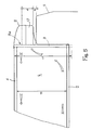
- a fairing according to the invention for a refrigeration unit equipping an isothermal cell placed aft of the cockpit 5 of a utility vehicle, is shown in position, in FIG. 5.
- said fairing occupies the space 3a left between the pavilions of the cell and of the cabin 5.
- the skirt 17 is produced by molding, so that its wall device is of a height h allowing it to be mounted in the case where this part 3a is the largest, and the skirt is then adjusted at the time of assembly by shortening it 17f, to adapt it to the fairing and to the vehicle, while providing an interval e between the skirt 17 and the roof of the cabin 5.
- the procedure is similar for the front wall 3 in order to adapt it to the isothermal cell of said vehicle.
- Said wall 3 and its enclosure 9 are therefore produced by molding, giving the wall a length L greater than the height H of the cell which must equip a vehicle of large dimensions and of higher power, and said wall 3 is shortened at the time the realization of the cell, depending on its height or the height of the cell fitted to vehicles of smaller dimensions.
Landscapes
- Engineering & Computer Science (AREA)
- Physics & Mathematics (AREA)
- Thermal Sciences (AREA)
- Mechanical Engineering (AREA)
- Health & Medical Sciences (AREA)
- Public Health (AREA)
- Transportation (AREA)
- Devices That Are Associated With Refrigeration Equipment (AREA)
Applications Claiming Priority (2)
| Application Number | Priority Date | Filing Date | Title |
|---|---|---|---|
| FR9016375A FR2670444B1 (fr) | 1990-12-18 | 1990-12-18 | Perfectionnements aux cellules isothermes de vehicules frigorifiques. |
| FR9016375 | 1990-12-18 |
Publications (2)
| Publication Number | Publication Date |
|---|---|
| EP0493281A1 true EP0493281A1 (de) | 1992-07-01 |
| EP0493281B1 EP0493281B1 (de) | 1995-05-24 |
Family
ID=9403751
Family Applications (1)
| Application Number | Title | Priority Date | Filing Date |
|---|---|---|---|
| EP91430026A Expired - Lifetime EP0493281B1 (de) | 1990-12-18 | 1991-12-11 | Fertigungsverfahren für isothermische Zellen von Kühlfahrzeugen |
Country Status (4)
| Country | Link |
|---|---|
| EP (1) | EP0493281B1 (de) |
| DE (1) | DE69110026T2 (de) |
| ES (1) | ES2075396T3 (de) |
| FR (1) | FR2670444B1 (de) |
Cited By (1)
| Publication number | Priority date | Publication date | Assignee | Title |
|---|---|---|---|---|
| RU2656919C1 (ru) * | 2017-06-05 | 2018-06-07 | Федеральное государственное бюджетное образовательное учреждение высшего образования "Кубанский государственный аграрный университет имени И.Т. Трубилина" | Автомобиль-рефрижератор |
Citations (3)
| Publication number | Priority date | Publication date | Assignee | Title |
|---|---|---|---|---|
| DE3113262A1 (de) * | 1981-04-02 | 1983-02-10 | Kunststoff Und Kaeltetechnik G | Kuehlfahrzeug, insbesondere zum transport von frischfleisch, obst oder gemuese |
| DE8323114U1 (de) * | 1983-08-11 | 1984-01-19 | SÜTRAK Transportkälte GmbH, 7253 Renningen | Kühlgerät für Gütertransportfahrzeuge mit Kastenaufbau |
| EP0366616A1 (de) * | 1988-10-26 | 1990-05-02 | SAPA S.p.A. | Aerodynamische Kühlungseinheit für Kraftfahrzeuge |
-
1990
- 1990-12-18 FR FR9016375A patent/FR2670444B1/fr not_active Expired - Fee Related
-
1991
- 1991-12-11 DE DE69110026T patent/DE69110026T2/de not_active Expired - Fee Related
- 1991-12-11 ES ES91430026T patent/ES2075396T3/es not_active Expired - Lifetime
- 1991-12-11 EP EP91430026A patent/EP0493281B1/de not_active Expired - Lifetime
Patent Citations (3)
| Publication number | Priority date | Publication date | Assignee | Title |
|---|---|---|---|---|
| DE3113262A1 (de) * | 1981-04-02 | 1983-02-10 | Kunststoff Und Kaeltetechnik G | Kuehlfahrzeug, insbesondere zum transport von frischfleisch, obst oder gemuese |
| DE8323114U1 (de) * | 1983-08-11 | 1984-01-19 | SÜTRAK Transportkälte GmbH, 7253 Renningen | Kühlgerät für Gütertransportfahrzeuge mit Kastenaufbau |
| EP0366616A1 (de) * | 1988-10-26 | 1990-05-02 | SAPA S.p.A. | Aerodynamische Kühlungseinheit für Kraftfahrzeuge |
Cited By (1)
| Publication number | Priority date | Publication date | Assignee | Title |
|---|---|---|---|---|
| RU2656919C1 (ru) * | 2017-06-05 | 2018-06-07 | Федеральное государственное бюджетное образовательное учреждение высшего образования "Кубанский государственный аграрный университет имени И.Т. Трубилина" | Автомобиль-рефрижератор |
Also Published As
| Publication number | Publication date |
|---|---|
| FR2670444B1 (fr) | 1995-08-04 |
| DE69110026D1 (de) | 1995-06-29 |
| DE69110026T2 (de) | 1995-11-30 |
| FR2670444A1 (fr) | 1992-06-19 |
| ES2075396T3 (es) | 1995-10-01 |
| EP0493281B1 (de) | 1995-05-24 |
Similar Documents
| Publication | Publication Date | Title |
|---|---|---|
| EP1991444A1 (de) | Batterieträger eines kraftfahrzeugs und wärmeschutzkasten für eine batterie mit derartigem träger | |
| FR2955077A1 (fr) | Vehicule dote d'un plancher apte a recevoir une batterie et une poutre de renforcement | |
| FR3063699B1 (fr) | Agencement de maintien d'un bac de coffre a l'avant d'une structure de caisse d'un vehicule automobile. | |
| EP0493281B1 (de) | Fertigungsverfahren für isothermische Zellen von Kühlfahrzeugen | |
| EP0838653A1 (de) | Wärmetauscher mit verbesserter Zufuhr für die Heizung, Lüftung und/ oder Klimaanlage, insbesondere für Kraftwagen | |
| EP3718865A1 (de) | Kühlvorrichtung für einen motorbereich eines fahrzeugs, und mit einer solchen vorrichtung ausgestattete motorhaube | |
| EP1152925B1 (de) | Stossfänger für ein kraftfahrzeug | |
| FR2983128A1 (fr) | Procede de fonctionnement d'un dispositif pour generer un rideau d'air pour un espace interieur, en particulier d'un vehicule routier | |
| EP0150636A1 (de) | Pressstoffstossstange | |
| EP4341116B1 (de) | Kühlmodul für ein elektro- oder hybridkraftfahrzeug mit einer tangentialflussturbomaschine | |
| FR3111977A1 (fr) | Échangeur thermique comprenant un organe de réduction de section d’un collecteur. | |
| FR2792398A1 (fr) | Installation pour le maintien a basse temperature d'une enceinte isothermique | |
| EP2873559B1 (de) | Isolierbehälter für Kühlfahrzeug | |
| FR2729282A1 (fr) | Meuble refrigere demontable | |
| EP3931018B1 (de) | Multifunktionshalterung für eine wärmekraftmaschine | |
| EP1195316B1 (de) | Armaturenträger für Kraftfahrzeug, und Kraftfahrzeug mit derartigen Armaturenträger | |
| FR2981735A1 (fr) | Dispositif generant un rideau d'air dans la baie d'acces a une enceinte de conservation | |
| FR2755506A1 (fr) | Condenseur a montage simplifie pour circuit de climatisation de vehicule | |
| FR3088144A1 (fr) | Boîtier de batterie | |
| FR3130204A1 (fr) | Véhicule électrique comportant un chargeur de batterie et une boîte de dégazage de fluide | |
| EP3448139B1 (de) | Elektronische ausrüstung, die einen befestigungsflansch umfasst | |
| FR2869585A1 (fr) | Element de carenage pour surfaces de dessous de vehicule | |
| FR2705085A1 (fr) | Dispositif de protection isotherme pour batterie de véhicules. | |
| WO2019101591A1 (fr) | Dispositif d'évacuation de la chaleur émise par un boîtier électronique | |
| EP0686822B1 (de) | Wärmetauscher für den Kühlungskreislauf eines Kraftfahrzeugs |
Legal Events
| Date | Code | Title | Description |
|---|---|---|---|
| PUAI | Public reference made under article 153(3) epc to a published international application that has entered the european phase |
Free format text: ORIGINAL CODE: 0009012 |
|
| AK | Designated contracting states |
Kind code of ref document: A1 Designated state(s): BE CH DE ES GB IT LI LU |
|
| 17P | Request for examination filed |
Effective date: 19920817 |
|
| 17Q | First examination report despatched |
Effective date: 19931025 |
|
| GRAA | (expected) grant |
Free format text: ORIGINAL CODE: 0009210 |
|
| AK | Designated contracting states |
Kind code of ref document: B1 Designated state(s): BE CH DE ES GB IT LI LU |
|
| REF | Corresponds to: |
Ref document number: 69110026 Country of ref document: DE Date of ref document: 19950629 |
|
| ITF | It: translation for a ep patent filed | ||
| GBT | Gb: translation of ep patent filed (gb section 77(6)(a)/1977) |
Effective date: 19950822 |
|
| REG | Reference to a national code |
Ref country code: ES Ref legal event code: FG2A Ref document number: 2075396 Country of ref document: ES Kind code of ref document: T3 |
|
| PGFP | Annual fee paid to national office [announced via postgrant information from national office to epo] |
Ref country code: GB Payment date: 19951205 Year of fee payment: 5 |
|
| PGFP | Annual fee paid to national office [announced via postgrant information from national office to epo] |
Ref country code: DE Payment date: 19951219 Year of fee payment: 5 |
|
| PGFP | Annual fee paid to national office [announced via postgrant information from national office to epo] |
Ref country code: ES Payment date: 19951220 Year of fee payment: 5 |
|
| PGFP | Annual fee paid to national office [announced via postgrant information from national office to epo] |
Ref country code: CH Payment date: 19951227 Year of fee payment: 5 |
|
| PG25 | Lapsed in a contracting state [announced via postgrant information from national office to epo] |
Ref country code: LU Free format text: LAPSE BECAUSE OF NON-PAYMENT OF DUE FEES Effective date: 19951231 |
|
| PGFP | Annual fee paid to national office [announced via postgrant information from national office to epo] |
Ref country code: BE Payment date: 19960117 Year of fee payment: 5 |
|
| PLBE | No opposition filed within time limit |
Free format text: ORIGINAL CODE: 0009261 |
|
| STAA | Information on the status of an ep patent application or granted ep patent |
Free format text: STATUS: NO OPPOSITION FILED WITHIN TIME LIMIT |
|
| 26N | No opposition filed | ||
| PG25 | Lapsed in a contracting state [announced via postgrant information from national office to epo] |
Ref country code: GB Effective date: 19961211 |
|
| PG25 | Lapsed in a contracting state [announced via postgrant information from national office to epo] |
Ref country code: ES Free format text: LAPSE BECAUSE OF EXPIRATION OF PROTECTION Effective date: 19961212 |
|
| PG25 | Lapsed in a contracting state [announced via postgrant information from national office to epo] |
Ref country code: LI Effective date: 19961231 Ref country code: CH Effective date: 19961231 Ref country code: BE Effective date: 19961231 |
|
| BERE | Be: lapsed |
Owner name: CARROSSERIE LAMBERT Effective date: 19961231 |
|
| GBPC | Gb: european patent ceased through non-payment of renewal fee |
Effective date: 19961211 |
|
| REG | Reference to a national code |
Ref country code: CH Ref legal event code: PL |
|
| PG25 | Lapsed in a contracting state [announced via postgrant information from national office to epo] |
Ref country code: DE Effective date: 19970902 |
|
| REG | Reference to a national code |
Ref country code: ES Ref legal event code: FD2A Effective date: 20010201 |
|
| PG25 | Lapsed in a contracting state [announced via postgrant information from national office to epo] |
Ref country code: IT Free format text: LAPSE BECAUSE OF NON-PAYMENT OF DUE FEES;WARNING: LAPSES OF ITALIAN PATENTS WITH EFFECTIVE DATE BEFORE 2007 MAY HAVE OCCURRED AT ANY TIME BEFORE 2007. THE CORRECT EFFECTIVE DATE MAY BE DIFFERENT FROM THE ONE RECORDED. Effective date: 20051211 |