EP0493307A2 - Elément photovoltaique et son utilisation, ainsi que méthode et appareillage pour sa fabrication - Google Patents
Elément photovoltaique et son utilisation, ainsi que méthode et appareillage pour sa fabrication Download PDFInfo
- Publication number
- EP0493307A2 EP0493307A2 EP91710055A EP91710055A EP0493307A2 EP 0493307 A2 EP0493307 A2 EP 0493307A2 EP 91710055 A EP91710055 A EP 91710055A EP 91710055 A EP91710055 A EP 91710055A EP 0493307 A2 EP0493307 A2 EP 0493307A2
- Authority
- EP
- European Patent Office
- Prior art keywords
- photovoltaic element
- laminator
- photovoltaic
- approximately
- web
- Prior art date
- Legal status (The legal status is an assumption and is not a legal conclusion. Google has not performed a legal analysis and makes no representation as to the accuracy of the status listed.)
- Ceased
Links
Images




Classifications
-
- H—ELECTRICITY
- H10—SEMICONDUCTOR DEVICES; ELECTRIC SOLID-STATE DEVICES NOT OTHERWISE PROVIDED FOR
- H10F—INORGANIC SEMICONDUCTOR DEVICES SENSITIVE TO INFRARED RADIATION, LIGHT, ELECTROMAGNETIC RADIATION OF SHORTER WAVELENGTH OR CORPUSCULAR RADIATION
- H10F19/00—Integrated devices, or assemblies of multiple devices, comprising at least one photovoltaic cell covered by group H10F10/00, e.g. photovoltaic modules
-
- F—MECHANICAL ENGINEERING; LIGHTING; HEATING; WEAPONS; BLASTING
- F24—HEATING; RANGES; VENTILATING
- F24S—SOLAR HEAT COLLECTORS; SOLAR HEAT SYSTEMS
- F24S25/00—Arrangement of stationary mountings or supports for solar heat collector modules
- F24S25/50—Arrangement of stationary mountings or supports for solar heat collector modules comprising elongate non-rigid elements, e.g. straps, wires or ropes
-
- H—ELECTRICITY
- H02—GENERATION; CONVERSION OR DISTRIBUTION OF ELECTRIC POWER
- H02S—GENERATION OF ELECTRIC POWER BY CONVERSION OF INFRARED RADIATION, VISIBLE LIGHT OR ULTRAVIOLET LIGHT, e.g. USING PHOTOVOLTAIC [PV] MODULES
- H02S20/00—Supporting structures for PV modules
- H02S20/10—Supporting structures directly fixed to the ground
-
- H—ELECTRICITY
- H10—SEMICONDUCTOR DEVICES; ELECTRIC SOLID-STATE DEVICES NOT OTHERWISE PROVIDED FOR
- H10F—INORGANIC SEMICONDUCTOR DEVICES SENSITIVE TO INFRARED RADIATION, LIGHT, ELECTROMAGNETIC RADIATION OF SHORTER WAVELENGTH OR CORPUSCULAR RADIATION
- H10F19/00—Integrated devices, or assemblies of multiple devices, comprising at least one photovoltaic cell covered by group H10F10/00, e.g. photovoltaic modules
- H10F19/90—Structures for connecting between photovoltaic cells, e.g. interconnections or insulating spacers
- H10F19/902—Structures for connecting between photovoltaic cells, e.g. interconnections or insulating spacers for series or parallel connection of photovoltaic cells
- H10F19/904—Structures for connecting between photovoltaic cells, e.g. interconnections or insulating spacers for series or parallel connection of photovoltaic cells characterised by the shapes of the structures
-
- H—ELECTRICITY
- H10—SEMICONDUCTOR DEVICES; ELECTRIC SOLID-STATE DEVICES NOT OTHERWISE PROVIDED FOR
- H10F—INORGANIC SEMICONDUCTOR DEVICES SENSITIVE TO INFRARED RADIATION, LIGHT, ELECTROMAGNETIC RADIATION OF SHORTER WAVELENGTH OR CORPUSCULAR RADIATION
- H10F19/00—Integrated devices, or assemblies of multiple devices, comprising at least one photovoltaic cell covered by group H10F10/00, e.g. photovoltaic modules
- H10F19/90—Structures for connecting between photovoltaic cells, e.g. interconnections or insulating spacers
- H10F19/902—Structures for connecting between photovoltaic cells, e.g. interconnections or insulating spacers for series or parallel connection of photovoltaic cells
- H10F19/906—Structures for connecting between photovoltaic cells, e.g. interconnections or insulating spacers for series or parallel connection of photovoltaic cells characterised by the materials of the structures
-
- Y—GENERAL TAGGING OF NEW TECHNOLOGICAL DEVELOPMENTS; GENERAL TAGGING OF CROSS-SECTIONAL TECHNOLOGIES SPANNING OVER SEVERAL SECTIONS OF THE IPC; TECHNICAL SUBJECTS COVERED BY FORMER USPC CROSS-REFERENCE ART COLLECTIONS [XRACs] AND DIGESTS
- Y02—TECHNOLOGIES OR APPLICATIONS FOR MITIGATION OR ADAPTATION AGAINST CLIMATE CHANGE
- Y02B—CLIMATE CHANGE MITIGATION TECHNOLOGIES RELATED TO BUILDINGS, e.g. HOUSING, HOUSE APPLIANCES OR RELATED END-USER APPLICATIONS
- Y02B10/00—Integration of renewable energy sources in buildings
- Y02B10/10—Photovoltaic [PV]
-
- Y—GENERAL TAGGING OF NEW TECHNOLOGICAL DEVELOPMENTS; GENERAL TAGGING OF CROSS-SECTIONAL TECHNOLOGIES SPANNING OVER SEVERAL SECTIONS OF THE IPC; TECHNICAL SUBJECTS COVERED BY FORMER USPC CROSS-REFERENCE ART COLLECTIONS [XRACs] AND DIGESTS
- Y02—TECHNOLOGIES OR APPLICATIONS FOR MITIGATION OR ADAPTATION AGAINST CLIMATE CHANGE
- Y02B—CLIMATE CHANGE MITIGATION TECHNOLOGIES RELATED TO BUILDINGS, e.g. HOUSING, HOUSE APPLIANCES OR RELATED END-USER APPLICATIONS
- Y02B10/00—Integration of renewable energy sources in buildings
- Y02B10/20—Solar thermal
-
- Y—GENERAL TAGGING OF NEW TECHNOLOGICAL DEVELOPMENTS; GENERAL TAGGING OF CROSS-SECTIONAL TECHNOLOGIES SPANNING OVER SEVERAL SECTIONS OF THE IPC; TECHNICAL SUBJECTS COVERED BY FORMER USPC CROSS-REFERENCE ART COLLECTIONS [XRACs] AND DIGESTS
- Y02—TECHNOLOGIES OR APPLICATIONS FOR MITIGATION OR ADAPTATION AGAINST CLIMATE CHANGE
- Y02E—REDUCTION OF GREENHOUSE GAS [GHG] EMISSIONS, RELATED TO ENERGY GENERATION, TRANSMISSION OR DISTRIBUTION
- Y02E10/00—Energy generation through renewable energy sources
- Y02E10/40—Solar thermal energy, e.g. solar towers
- Y02E10/47—Mountings or tracking
-
- Y—GENERAL TAGGING OF NEW TECHNOLOGICAL DEVELOPMENTS; GENERAL TAGGING OF CROSS-SECTIONAL TECHNOLOGIES SPANNING OVER SEVERAL SECTIONS OF THE IPC; TECHNICAL SUBJECTS COVERED BY FORMER USPC CROSS-REFERENCE ART COLLECTIONS [XRACs] AND DIGESTS
- Y02—TECHNOLOGIES OR APPLICATIONS FOR MITIGATION OR ADAPTATION AGAINST CLIMATE CHANGE
- Y02E—REDUCTION OF GREENHOUSE GAS [GHG] EMISSIONS, RELATED TO ENERGY GENERATION, TRANSMISSION OR DISTRIBUTION
- Y02E10/00—Energy generation through renewable energy sources
- Y02E10/50—Photovoltaic [PV] energy
Definitions
- the invention relates to a photovoltaic element with a barrier layer provided between two layers, which is provided, in particular, for separating charge carrier pairs or the like which have arisen or diffused therein, the photovoltaic element on a carrier made of elastic material, for example on a membrane or a tent fabric, is arranged.
- the invention covers an application of the photovoltaic element as well as a method and a device for its production.
- DE-OS 34 27 574 describes a device for shading surfaces, in particular for shading walk-in places or the like, with at least one or the like on supports. Supporting elements at a distance from the roof covering stretched out to be shaded or the like. Flexible supporting structure on which photovoltaic elements are provided as a layer or as silicon crystals which can be moved relative to one another. Photovoltaic elements have a multilayer structure; a barrier layer separates systems from semiconductor / semiconductor, semiconductor / electrolyte, semiconductor / metal or metal / electrolyte.
- a so-called photo effect occurs in the barrier layer or in its immediate vicinity; Charge carrier pairs (excitons) or the like generated by the incidence of light, diffused into this barrier layer from the surroundings or formed in the barrier layer are separated in the electrical field of the barrier layer, whereby a usable voltage is generated.
- an upper negatively doped (such as silicon with phosphorus atoms) and a lower (boron atoms) positive doped layer built - electrical barrier can be taken directly from metal contacts direct current, which can then be adapted to the power grid by inverters. For this reason, such photovoltaic elements are connected directly to power lines.
- a photovoltaic solar module is reinforced according to DE-OS 31 42 129 by a galvanized iron wire mesh or iron wire mesh, which carries a lacquer layer and with which the plastic covering the solar cell - with the interposition of a multilayer film as a vapor diffusion barrier - is connected.
- a glass fabric and the electrical cables can run in the plastic.
- This solar module is said to be outside the area of its rigid surfaces which are backed by stiff material, such as uneven floors, car roofs, rock walls, house fronts or the like. can be adapted, this adaptation to the curvature takes place shaping once, namely when hanging up.
- Such solar modules are just as unsuitable for moving curved surfaces as photovoltaic layers made of amorphous silicon or of cadmium derivatives, for example according to US Pat. No. 3,411,050.
- a large-scale photovoltaic module consists of several solar areas articulated to one another and can be folded or rolled. It is an amorphous module with efficiencies in the range of 4 to 5%.
- the inventor Since the prior art provides either individual rigid solar modules made of crystalline solar cells or small flexible modules, the inventor has set itself the goal of creating a photovoltaic element and a method for this, with which this element can be integrated in tissue membranes. The aim is to create an inseparable and permanent connection between rigid solar cells and flexible fabric membranes - especially for photovoltaic membrane structures, shading systems, canopies or the like - while maintaining the functionality of both starting materials.
- a device for carrying out the method and a special use of the photovoltaic element are to be offered.
- a structure of a photovoltaic module that is particularly suitable for laminating onto coated fabric webs is therefore presented.
- the solar cells are interconnected to form modules depending on the electrical requirements.
- cell connectors made of folded metallic conductor strips or of conductive elastomers are used with one another.
- the cover layer is corona-treated before the lamination process to increase the surface tension.
- the corona treatment takes place during the passage through an electrode system and a counter electrode designed as a roller at 20 kV and 60 kHz.
- the surface tension to be achieved is set to approx. 46 mN / m.
- the permanent elastic connection between the solar cell and the fabric web is created by an adhesive thermoplastic polymer layer, which in particular has elastomeric copolymers of ethylene and vinyl acetate (EVA), EVB, silicones or the like.
- EVA ethylene and vinyl acetate
- the polymer layer is preferably used in the form of a film.
- a disk made of a material with a high modulus of elasticity, such as metal or reinforced plastic, or supported at the front - i.e. towards the light incidence side - by a thin one Glass pane. At the front, this element is still protected against environmental influences by a polymer film. To improve adhesion, this film is also corona-treated on the inward side.
- the laminate is constructed in the form of a sandwich from the layers described and between a connecting, elastic polymer layer between each of these functional elements.
- This completely layered module structure is applied to the tent fabric or similar material web and laminated in the vacuum laminator at approx. 10 mbar and 150 ° C.
- the fabric web or roof skin separates two vacuum chambers.
- the upper and lower parts of the laminator advantageously each have their own sealing frames made of heat-resistant elastomer, which ensure the vacuum seal to the intervening fabric web during the lamination process.
- the fabric or carrier web is pressed onto the solar cell structure and the two are firmly connected to one another.
- the laminator is opened and the carrier web is shifted in the longitudinal direction in order to be able to carry out the subsequent lamination of the subsequent section.
- the process is repeated periodically and a continuously coated fabric web is created.
- many solar modules are to be connected in series in larger photovoltaic systems in order to minimize the power losses.
- the power is then transmitted through a higher voltage.
- around forty cells are connected in series in each solar module and their manufacturing tolerance in terms of efficiency causes certain defects.
- Those disadvantages of the module are superimposed on those of the series connection. For this reason, it must be ensured that the solar modules are connected in series in larger systems.
- the choice according to the invention of a small system voltage largely prevents the problem of mismatching of modules connected in series with different angles of attack.
- Light surface structures always have curvatures, so that additional errors are caused here by solar modules connected in series with different angles of attack - and thus modules with different incidence of light.
- solar modules with approximately the same orientation are interconnected to form strings in a photovoltaic system.
- the system should be divided into areas and each area should be assigned its own MPP controller; the optimal working point is set for each area.
- the current supplied by the modules is "chopped up” and transformed up or down via certain control loops.
- a constant voltage is always required at the output of these controls, either to charge a battery or to convert this constant DC voltage into AC voltage using generally known inverters and to build up a so-called regenerative power supply.
- MPP regulations work on the principle of continuous performance measurement. Any operating point on the characteristic is approached and a short time later another point on the characteristic (time range milliseconds to minutes). If the power in the second working point is greater than in the first measured point, a new working point is selected in the same direction and then compared again. If the power is greater in the first operating point, another point is scanned in the other direction. In this way there is continuous maximum power point tracking.
- Such devices are state of the art and are to be used according to the invention in an optimized manner in order to solve the problem that arises in the case of elevations with different modules connected in series To minimize angles of attack. In addition, this measure achieves an improved energy yield in conventional systems and certain shading problems.
- the entire system can be adapted to the course of the sun; In the mornings, the area with an east orientation works in the optimal working point, during the lunchtime the middle area is excellently irradiated, and in the afternoon, the west-facing area delivers the greatest performance. None of these areas - because they are electrically independent - is influenced by the others.
- the output voltages of the individual MPP controllers can be set to one value and thus feed a common consumer or battery storage.
- a conventional MPP controller consists of several power units, which is why only additional control units would be required.
- the power P for uniformly aligned solar modules is plotted against the electrical voltage U with the point M at the curve maximum; With optimal use of the solar generator, this is the position of the working point for the adjustable solar modules.
- a control system (not shown) of an MPP controller scans the characteristic curve of the solar generator. The power is calculated from the respective current and voltage values. If the power is greater at the next scanned point, the scan direction is maintained; if it is smaller, it is scanned in the opposite direction and the MPP point is found and recorded.
- the overall characteristic curve corresponding to the representation in FIG. 1 for differently aligned solar modules is shown in FIG. 3; in this case the overall characteristic curve is deformed.
- the power is lower than with uniformly aligned solar modules, which is illustrated by the power curve in FIG. 4.
- solar modules 20 are fixed to a cable network 10, which is curved between two high points 12, a high point 13 and a low point 14 and two low points 14.
- the position of these cable network nodes 16, of which only a few can be seen, is determined by inner cables 18, 19 crossing within edge cables 17.
- the solar modules 20 are each grouped into areas 20 a to 20 d , the central area 20 a - and for the most part also area 20 b - facing the zenith, thus primarily receiving the midday sun.
- the areas 20 c and 20 d are more assigned to the east and west respectively, so they take in the morning and evening sun.
- the edge cables 17 between the tension points 13 and 14 adjacent solar modules 20 ' b , 20' c , 20 ' d are connected by means of central connecting members 21 to the cable network node 16, the other solar modules 20 a to 20 d each one of four cable network nodes 16 determined mesh assigned, ie the narrow sides of their module frames (not illustrated in FIG. 5) run above the inner side 19 and lie with the longitudinal axis on a cable network node 16.
- At least four solar modules 20 of an area connecting power lines and their connections to a current sensor are also not recognizable.
- a working voltage of 48 V is fixed, for which purpose four solar modules 20 are always connected in series.
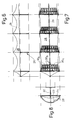
- a so-called wave arcade according to FIGS. 6 to 8 consists of a support frame 26, which contains vertical stands 22 and clamping arches 23 on horizontal supports 24, and a roof skin 28 stretched thereon, which forms a chain-line-like ridge line 29.
- solar modules 30 are arranged in three groups 30 a , 30 b , 30 c , of which the middle group 30 b is primarily exposed to solar energy at noon, the flanking groups 30 a and 30 c but before noon or in the afternoon.
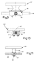
- the solar module 20 'of FIG. 9 can be fixed to the cable network 10, for example by a plastic base 32, which is screwed onto sleeves 33 of the cable network node 16 and acts as a buffer. Its hardness is, for example, about 20 to 30 (Shore A) for a solar module 20 of length n of 1000 mm and width b of 500 mm according to FIG. 12.
- Fig. 10 shows a solar module 20 'on a rope 11 of a cable network 10; it is fixed to the rope 11 by a rope clamp 46 with clamping plates 47 attached on both sides of the rope 11 and connected by screws 38. This clamp connection 11/46 slips from a defined force acting on the solar module 20 '.
- one of the fastening points should be rigid, whereas the other fastening points only absorb pressure or suction forces.
- the combination of fixed points with sliding areas - on rope or slip clamps 46 - compensates for the movements of the substructure 10, 28 relative to the solar module 20, 30.
- the solar module 30 according to FIG. 11 is fixed with the interposition of the plastic base 32 described above on a membrane-like roof skin 28 by means of screws 38 which pass through punched holes 40 and washers 39 and can be tightened via a nut 41.
- a module frame 34 of the solar module 30 shown in plan view in FIG. 12 can be firmly connected at points 35 to the load-bearing roof skin 28, not shown here, but can be displaceably mounted at points 36 by means of slip clamps.
- FIG. 13 The fixing of a solar module 30 on the roof skin 28 by means of a screw 38 is also sketched in FIG. 13; the roof skin 28 is held around the hole 40 penetrated by the screw 38 on both sides by clamping plates 42 lying between the nuts 41, which receive 43 O-rings 44 in grooves 43.
- Fig. 14 shows two adjacent solar modules 30, 30 ', of which the left is equipped with a fixing screw 38 and the right with a slot 48 offering slip clamp 49.
- the solar modules 30 e of Fig. 15 are fixed on a glass or plastic film 52 by means of a soft encapsulant material 50 and a glass surface 54 covered; the distances between the layers - for example the distance h between the plane of the solar modules 30 e and the glass surface 54 - are chosen to be excessive in both FIGS.
- FIG. 16 shows on a highly tear-resistant membrane - with chain 27 and weft 27 s as roof skin 28 a - soft embedding material 50, then stabilizing plates 56, which are followed by solar modules 30 e upwards.
- the latter spans a highly transparent plastic film 55.
- the solar modules can be integrated into the roof skin 28 a .
- a laminator can be used for the lamination, in which a fabric layer is placed as a laminate carrier on a heating plate spanned by an upper laminator part.
- a laminate with a layer structure as has been described above for photovoltaic elements, rests on this;
- a barrier layer for separating charge carrier pairs is provided between an outer layer pair consisting of a semiconductor layer on the one hand and an electrolyte or a metal on the other hand or between metal and an electrolyte.
- a silicone mat as a seal is stretched over the fabric section resting in the lower part of the laminator and the laminate on top, the edge area of which is held clamped between frame parts; the lower frame part defines an opening level of the laminator described, which runs below and at a distance from that silicone mat.
- the component created by the lamination of known type at about 10 mbar and 150 ° C in vacuum from the previously corona-treated fabric section and the multilayer Laminate is connected to form modules by cell connectors made of folded metallic conductor strips or electrically conductive elastomers.
- a laminator 58 with laminator base part 59 and laminator upper part 60 is indicated in FIG. 17; a continuous fabric web 64 is laminated with this laminator 58; this travels - coming from a feed tray 66 - through a gap 68 between the laminator base 59 and the upper laminator part 60 in their opening plane E, which is bounded at the top and bottom by a silicone sealing frame 62, 63.
- the stretched fabric web 64 separates an upper vacuum chamber 70 from a lower vacuum chamber 72.
- the fabric web 64 is pressed onto the sandwich structure of the laminate 61, which is held by a heating plate 74, and connected to it.
- the laminator 58 is opened and the carrier or fabric web 64 is shifted by a laminator length for a new lamination section (arrow x).
Landscapes
- Engineering & Computer Science (AREA)
- Physics & Mathematics (AREA)
- Life Sciences & Earth Sciences (AREA)
- Sustainable Development (AREA)
- Sustainable Energy (AREA)
- Thermal Sciences (AREA)
- Chemical & Material Sciences (AREA)
- Combustion & Propulsion (AREA)
- Mechanical Engineering (AREA)
- General Engineering & Computer Science (AREA)
- Photovoltaic Devices (AREA)
Applications Claiming Priority (2)
| Application Number | Priority Date | Filing Date | Title |
|---|---|---|---|
| DE4042014 | 1990-12-28 | ||
| DE4042014 | 1990-12-28 |
Publications (2)
| Publication Number | Publication Date |
|---|---|
| EP0493307A2 true EP0493307A2 (fr) | 1992-07-01 |
| EP0493307A3 EP0493307A3 (en) | 1993-04-28 |
Family
ID=6421584
Family Applications (1)
| Application Number | Title | Priority Date | Filing Date |
|---|---|---|---|
| EP19910710055 Ceased EP0493307A3 (en) | 1990-12-28 | 1991-12-21 | Photovoltaic element and its use, as well as method and apparatus for manufacturing it |
Country Status (2)
| Country | Link |
|---|---|
| EP (1) | EP0493307A3 (fr) |
| DE (1) | DE4142566C2 (fr) |
Cited By (5)
| Publication number | Priority date | Publication date | Assignee | Title |
|---|---|---|---|---|
| US6500746B2 (en) | 2000-02-24 | 2002-12-31 | Micron Technology, Inc. | Stereolithographically fabricated conductive elements, semiconductor device components and assemblies including such conductive elements, and methods |
| WO2006130892A1 (fr) * | 2005-06-06 | 2006-12-14 | Innova Patent Gmbh | Installation de production d'energie electrique |
| WO2010006460A3 (fr) * | 2008-07-14 | 2010-07-08 | Solar Wings Ag | Installation solaire |
| EP2309203A1 (fr) * | 2009-10-08 | 2011-04-13 | Rauschert Heinersdorf-Pressig GmbH | Dispositif et procédé de fixation d'une multitude de modules solaires sur la paroi extérieure d'un bâtiment |
| IT202300006231A1 (it) * | 2023-03-30 | 2024-09-30 | Aldo Cattano | Sistema per proteggere superfici innevate e/o ghiacciate da irraggiamento solare e metodo associato |
Families Citing this family (5)
| Publication number | Priority date | Publication date | Assignee | Title |
|---|---|---|---|---|
| DE19828462A1 (de) * | 1998-06-26 | 2000-01-05 | Alwitra Gmbh & Co Klaus Goebel | Dachbahn für Dachabdichtungen zum Schutz eines Bauwerks |
| DE19831692C2 (de) * | 1998-07-15 | 2003-12-24 | Thomas Gerhardt | Hybride Anlage für die Nutzung von Windkraft udn Solarenergie |
| DE19950500C2 (de) * | 1999-10-20 | 2001-12-20 | Uwe Rudolf Brueckner | Doppelwandiges Folienfeld, insbesondere Folienwandsegment |
| DE10028001A1 (de) * | 2000-04-12 | 2001-10-25 | Mueller Hermann Frank | Markise |
| DE102012021697B4 (de) | 2012-10-30 | 2015-02-19 | Friedrich Grimm | Tragsystem für die Stabilisierung von mindestens einem Mast |
Family Cites Families (10)
| Publication number | Priority date | Publication date | Assignee | Title |
|---|---|---|---|---|
| US2962539A (en) * | 1958-12-02 | 1960-11-29 | Arthur F Daniel | Solar cell array |
| US3780424A (en) * | 1970-10-26 | 1973-12-25 | Nasa | Method of making silicon solar cell array |
| DE2757301A1 (de) * | 1977-12-22 | 1979-07-05 | Leybold Heraeus Gmbh & Co Kg | Vorrichtung zur umwandlung von strahlung in elektrische energie und verfahren zur herstellung der vorrichtung |
| FR2466865A1 (fr) * | 1979-09-28 | 1981-04-10 | Radiotechnique Compelec | Procede de fabrication de panneaux de photopiles solaires, moyen permettant cette fabrication et panneaux fabriques par ce procede |
| DE3142129A1 (de) * | 1981-07-23 | 1983-03-03 | Siemens AG, 1000 Berlin und 8000 München | Photovoltaisches solarmodul |
| DE3427574A1 (de) * | 1984-07-26 | 1986-02-06 | Stromeyer Ingenieurbau GmbH, 7750 Konstanz | Vorrichtung zur beschattung von flaechen |
| DE3520423A1 (de) * | 1985-06-07 | 1986-12-11 | Telefunken electronic GmbH, 7100 Heilbronn | Solarzellenmodul |
| US4713492A (en) * | 1985-10-21 | 1987-12-15 | Energy Conversion Devices, Inc. | Stowable large area solar power module |
| WO1989002055A1 (fr) * | 1987-08-24 | 1989-03-09 | Luecke Nominees Pty. Ltd. | Dispositif de conversion de l'energie solaire |
| DE59010720D1 (de) * | 1989-01-17 | 1997-07-10 | Webasto Systemkomponenten Gmbh | Vorrichtung mit einer flexiblen Fläche zur Aufnahme fotovoltaischer Zellen |
-
1991
- 1991-12-21 EP EP19910710055 patent/EP0493307A3/de not_active Ceased
- 1991-12-21 DE DE4142566A patent/DE4142566C2/de not_active Expired - Fee Related
Cited By (13)
| Publication number | Priority date | Publication date | Assignee | Title |
|---|---|---|---|---|
| US6977211B2 (en) | 2000-02-24 | 2005-12-20 | Micron Technology, Inc. | Selective consolidation processes for electrically connecting contacts of semiconductor device components |
| US6764933B2 (en) | 2000-02-24 | 2004-07-20 | Micron Technology, Inc. | Stereolithographically fabricated conductive elements, semiconductor device components and assemblies including such conductive elements, and methods |
| US6764935B2 (en) | 2000-02-24 | 2004-07-20 | Micron Technology, Inc. | Stereolithographic methods for fabricating conductive elements |
| US6767815B2 (en) | 2000-02-24 | 2004-07-27 | Micron Technology, Inc. | Stereolithographically fabricated conductive elements, semiconductor device components and assemblies including such conductive elements, and methods |
| US6780744B2 (en) | 2000-02-24 | 2004-08-24 | Micron Technology, Inc. | Stereolithographic methods for securing conductive elements to contacts of semiconductor device components |
| US6815253B2 (en) | 2000-02-24 | 2004-11-09 | Micron Technology, Inc. | Stereolithographically fabricated conductive elements, semiconductor device components and assemblies including such conductive elements, and methods |
| US6500746B2 (en) | 2000-02-24 | 2002-12-31 | Micron Technology, Inc. | Stereolithographically fabricated conductive elements, semiconductor device components and assemblies including such conductive elements, and methods |
| US7137193B2 (en) | 2000-02-24 | 2006-11-21 | Micron Technology, Inc. | Programmed material consolidation methods for fabricating printed circuit board |
| US7273802B2 (en) | 2000-02-24 | 2007-09-25 | Micron Technology, Inc. | Methods for consolidating previously unconsolidated conductive material to form conductive structures or contact pads or secure conductive structures to contact pads |
| WO2006130892A1 (fr) * | 2005-06-06 | 2006-12-14 | Innova Patent Gmbh | Installation de production d'energie electrique |
| WO2010006460A3 (fr) * | 2008-07-14 | 2010-07-08 | Solar Wings Ag | Installation solaire |
| EP2309203A1 (fr) * | 2009-10-08 | 2011-04-13 | Rauschert Heinersdorf-Pressig GmbH | Dispositif et procédé de fixation d'une multitude de modules solaires sur la paroi extérieure d'un bâtiment |
| IT202300006231A1 (it) * | 2023-03-30 | 2024-09-30 | Aldo Cattano | Sistema per proteggere superfici innevate e/o ghiacciate da irraggiamento solare e metodo associato |
Also Published As
| Publication number | Publication date |
|---|---|
| EP0493307A3 (en) | 1993-04-28 |
| DE4142566A1 (de) | 1992-07-02 |
| DE4142566C2 (de) | 1998-09-10 |
Similar Documents
| Publication | Publication Date | Title |
|---|---|---|
| EP0494043B1 (fr) | Dispositif pour donner de l'ombre à des surfaces au moyen d'une membrane de toiture tendue comportant des éléments photovoltaiques | |
| EP1297577B1 (fr) | Procede de production d'un module photovoltaique a couches minces | |
| EP3969691B1 (fr) | Colonne comprenant au moins un élément photovoltaïque et utilisation d'un élément photovoltaïque sur une colonne | |
| DE102009022125A1 (de) | Isolierglasverbund mit schräg angeordneten Photovoltaik Zellen und Verfahren zur Herstellung und Anwendung | |
| DE10109643B4 (de) | Dünnschicht-Photovoltaikmodul aus mehreren Teilmodulen und Herstellungsverfahren hierfür | |
| DE102009004195A1 (de) | Solar-Modul in einem Isolierglasverbund und Verfahren zur Herstellung und Anwendung | |
| DE102009026149A1 (de) | Verbundsystem für Photovoltaik-Module | |
| EP0493307A2 (fr) | Elément photovoltaique et son utilisation, ainsi que méthode et appareillage pour sa fabrication | |
| EP0379961B1 (fr) | Dispositif de surface flexible pour supporter des cellules photovoltaiques | |
| DE102008050529A1 (de) | Photovoltaikanlage, Photovoltaikmodul, Unterkonstruktion und Verfahren zur Bestückung einer Photovoltaikanlage | |
| EP2277204A2 (fr) | Système pour produire du courant solaire | |
| EP2831924A1 (fr) | Module photovoltaïque doté d'un dispositif refroidisseur | |
| EP1267418B1 (fr) | Module de montage pour cellules solaires | |
| DE112015001881T5 (de) | Photoelektrische Stromerzeugungsvorrichtung | |
| DE102011089916A1 (de) | Solarzellenanordnung in Tandem-Konfiguration | |
| DE3419299A1 (de) | Modul fuer photovoltaische solarzellen | |
| DE10046134A1 (de) | Dach- und Fassadenschindel | |
| EP2538455A1 (fr) | Petite centrale transportable pour la transformation de lumière solaire en énergie électrique et procédé d'établissement d'une telle petite centrale | |
| WO2023217453A1 (fr) | Procédé d'interconnexion d'un réseau de cellules solaires, module solaire et dispositif pour l'interconnexion électrique de réseaux de cellules solaires | |
| DE102016125637A1 (de) | Photovoltaik-Modul und Verfahren zur Herstellung eines Photovoltaik-Moduls | |
| DE202008008743U1 (de) | Photovoltaisches Solarmodul | |
| EP4260380B1 (fr) | Structure de tissu comprenant des cellules solaires flexibles | |
| DE10131234B4 (de) | Elektrische Anschlusseinheit für flexible, unterseitig vlieskaschierte Dachabdichtungsbahnen sowie mit diesen verbundenen, nichtstarren photovoltaischen Flächenzellen | |
| EP2590230A2 (fr) | Installation photovoltaïque à surface libre | |
| EP1230480B1 (fr) | Installation hybride pour exploiter l'energie solaire et eolienne |
Legal Events
| Date | Code | Title | Description |
|---|---|---|---|
| PUAI | Public reference made under article 153(3) epc to a published international application that has entered the european phase |
Free format text: ORIGINAL CODE: 0009012 |
|
| AK | Designated contracting states |
Kind code of ref document: A2 Designated state(s): AT BE CH DE DK ES FR GB GR IT LI LU MC NL SE |
|
| 17P | Request for examination filed |
Effective date: 19920805 |
|
| RBV | Designated contracting states (corrected) |
Designated state(s): AT CH DE ES FR GR IT LI MC |
|
| PUAL | Search report despatched |
Free format text: ORIGINAL CODE: 0009013 |
|
| AK | Designated contracting states |
Kind code of ref document: A3 Designated state(s): AT BE CH DE DK ES FR GB GR IT LI LU MC NL SE |
|
| RAP1 | Party data changed (applicant data changed or rights of an application transferred) |
Owner name: WUR GESELLSCHAFT FUER VERMOEGENSVERWALTUNG MBH |
|
| 17Q | First examination report despatched |
Effective date: 19950601 |
|
| RAP1 | Party data changed (applicant data changed or rights of an application transferred) |
Owner name: WEBASTO SYSTEMKOMPONENTEN GMBH |
|
| 18R | Application refused |
Effective date: 19990421 |