EP0493954B1 - Joint de culasse en acier stratifié - Google Patents
Joint de culasse en acier stratifié Download PDFInfo
- Publication number
- EP0493954B1 EP0493954B1 EP19910311930 EP91311930A EP0493954B1 EP 0493954 B1 EP0493954 B1 EP 0493954B1 EP 19910311930 EP19910311930 EP 19910311930 EP 91311930 A EP91311930 A EP 91311930A EP 0493954 B1 EP0493954 B1 EP 0493954B1
- Authority
- EP
- European Patent Office
- Prior art keywords
- plate
- gasket
- cylinder head
- cylinder bore
- laminate type
- Prior art date
- Legal status (The legal status is an assumption and is not a legal conclusion. Google has not performed a legal analysis and makes no representation as to the accuracy of the status listed.)
- Expired - Lifetime
Links
Images

Classifications
-
- F—MECHANICAL ENGINEERING; LIGHTING; HEATING; WEAPONS; BLASTING
- F16—ENGINEERING ELEMENTS AND UNITS; GENERAL MEASURES FOR PRODUCING AND MAINTAINING EFFECTIVE FUNCTIONING OF MACHINES OR INSTALLATIONS; THERMAL INSULATION IN GENERAL
- F16J—PISTONS; CYLINDERS; SEALINGS
- F16J15/00—Sealings
- F16J15/02—Sealings between relatively-stationary surfaces
- F16J15/06—Sealings between relatively-stationary surfaces with solid packing compressed between sealing surfaces
- F16J15/08—Sealings between relatively-stationary surfaces with solid packing compressed between sealing surfaces with exclusively metal packing
- F16J15/0818—Flat gaskets
- F16J15/0825—Flat gaskets laminated
-
- F—MECHANICAL ENGINEERING; LIGHTING; HEATING; WEAPONS; BLASTING
- F02—COMBUSTION ENGINES; HOT-GAS OR COMBUSTION-PRODUCT ENGINE PLANTS
- F02F—CYLINDERS, PISTONS OR CASINGS, FOR COMBUSTION ENGINES; ARRANGEMENTS OF SEALINGS IN COMBUSTION ENGINES
- F02F11/00—Arrangements of sealings in combustion engines
- F02F11/002—Arrangements of sealings in combustion engines involving cylinder heads
-
- F—MECHANICAL ENGINEERING; LIGHTING; HEATING; WEAPONS; BLASTING
- F16—ENGINEERING ELEMENTS AND UNITS; GENERAL MEASURES FOR PRODUCING AND MAINTAINING EFFECTIVE FUNCTIONING OF MACHINES OR INSTALLATIONS; THERMAL INSULATION IN GENERAL
- F16J—PISTONS; CYLINDERS; SEALINGS
- F16J15/00—Sealings
- F16J15/02—Sealings between relatively-stationary surfaces
- F16J15/06—Sealings between relatively-stationary surfaces with solid packing compressed between sealing surfaces
- F16J15/08—Sealings between relatively-stationary surfaces with solid packing compressed between sealing surfaces with exclusively metal packing
- F16J15/0818—Flat gaskets
- F16J2015/0837—Flat gaskets with an edge portion folded over a second plate or shim
-
- F—MECHANICAL ENGINEERING; LIGHTING; HEATING; WEAPONS; BLASTING
- F16—ENGINEERING ELEMENTS AND UNITS; GENERAL MEASURES FOR PRODUCING AND MAINTAINING EFFECTIVE FUNCTIONING OF MACHINES OR INSTALLATIONS; THERMAL INSULATION IN GENERAL
- F16J—PISTONS; CYLINDERS; SEALINGS
- F16J15/00—Sealings
- F16J15/02—Sealings between relatively-stationary surfaces
- F16J15/06—Sealings between relatively-stationary surfaces with solid packing compressed between sealing surfaces
- F16J15/08—Sealings between relatively-stationary surfaces with solid packing compressed between sealing surfaces with exclusively metal packing
- F16J15/0818—Flat gaskets
- F16J2015/0862—Flat gaskets with a bore ring
Definitions
- the present invention relates to a steel laminate type cylinder head gasket for an internal combustion engine with an auxiliary combustion chamber.
- a cylinder head In an engine with an auxiliary combustion chamber, a cylinder head is provided with a mouth plate to close the auxiliary combustion chamber.
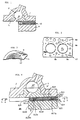
- a cylinder head J is provided with a depression K, to which a mouth plate L is inserted, so that an auxiliary combustion chamber M is defined inside the depression K.
- a gasket 10 is installed between the cylinder head J and a cylinder block P to seal therebetween.
- the mouth plate L is supported partly by a portion N of the gasket 10.
- the gasket 10 is formed of an upper plate, lower plate and three middle plates. A wire ring is installed around the cylinder bore Hc. Since the gasket 10 does not resiliently support the mouth plate, combustion gas is liable to leak through the mouth plate.
- one of the middle plate is replaced by a plate 11 with beads 12 at the portion N of the gasket, which is disclosed in Japanese Patent Publication (KOKAI) No. 59-90745.
- one object of the invention is to provide a steel laminate type cylinder head gasket, which can securely support a mouth plate even if high pressure is applied to the mouth plate.
- Another object of the invention is to provide a steel laminate type cylinder head gasket as stated above, which can securely seal around the cylinder bore and the mouth plate while resiliently supporting the mouth plate.
- a further object of the invention is to provide a steel laminate type cylinder head gasket as stated above, which can be easily and economically manufactured.
- a steel laminate type cylinder head gasket to be installed in an internal combustion engine between a cylinder block with a cylinder bore and a cylinder head with an auxiliary combustion chamber, a mouth plate being attached to the cylinder head for closing said auxiliary combustion chamber and being partly supported by a portion of the gasket
- the gasket comprising: an upper plate having a downwardly curved portion surrounding the cylinder bore, a first middle plate and a second plate, sealing means provided in the downwardly curved portion of said upper plate to surround the cylinder bore and seal said bore, the first middle plate extending substantially throughout an entire area of the gasket, said first middle plate having a first hole corresponding to the cylinder bore of the engine, the second plate being adjacent under said first middle plate with a hole corresponding to the cylinder bore and having a bead extending at least partly around the cylinder bore, said gasket being characterized in that: the first middle plate has a second hole situated adjacent to the first hole under a part of the mouth plate, said second hole being defined by
- the elongated strip is defined between the first and second holes.
- the elongated strip may be integrally formed with the first middle plate, or separately formed therewith.
- the supporting means for the mouth plate is situated on or around the elongated strip.
- the upper plate is situated above the first middle plate and includes a curved portion situated around a third hole for the cylinder bore, and a flange extending in a direction away from the third hole. Also, the second plate is situated under the first middle plate. The flange of the upper plate is located under an edge portion of a hole of the second plate. A wire ring is used as the sealing means, and is located between the curved portion and the first middle plate.
- the supporting means for the mouth plate is situated near the sealing means so that the supporting means and the sealing means support the mouth plate near the cylinder bore.
- the supporting means may be a thin metal plate having a size at least equal to a size of the elongated strip, and is laminated over the elongated strip.
- the thin metal plate may extend around the cylinder bore entirely.
- the second plate may include a bead situated under the elongated strip for supporting the same.
- the bead and the elongated strip constitute the supporting means.
- the bead may extend around the cylinder bore and/or the second hole to seal therearound.
- the elongated strip is formed separately from the first middle plate, the elongated strip is made of a thick metal plate thicker than the first metal plate.
- the thick metal plate constitutes the supporting means for the mouth plate.
- the supporting means is situated between the sealing means and the compressible member. Therefore, in case the mouth plate is strongly urged against the gasket when the engine is started, the gasket is not damaged at all. Also, since the compressible member is situated in the second hole, the mouth plate is supported at a moderate pressure when the gasket is tightened.
- a first embodiment A of a steel laminate type cylinder head gasket of the invention is shown.
- the gasket A includes a plurality of cylinder bores Hc, water holes Hw, oil holes Ho, bolt holes Hb and so on, as in the conventional gasket shown in Fig. 2. Since the present invention is directed to a sealing mechanism around the cylinder bore Hc, sealing means for sealing around other holes is not explained. Any sealing means may be used for sealing around other holes.
- the gasket A of the invention is installed between a cylinder head J and a cylinder block P.
- the cylinder head J includes a mouth plate L to form an auxiliary combustion chamber M therein.
- the mouth plate L is supported by the gasket A at a portion N'.
- the gasket A is formed of an upper plate A11, three middle plates A12, A13, A14 and a lower plate A15, which extend substantially throughout the entire area of the engine.
- a wire ring A16 is situated around the cylinder bore Hc.
- the upper plate A11 includes a curved portion A11a to define the cylinder bore Hc, and a flange A11b extending from the curved portion A11a.
- the wire ring A16 is situated adjacent to the curved portion A11a.
- the first middle plate A12 includes a hole A12a near the cylinder bore Hc.
- the hole A12a is defined by an outer line A12b larger than a part of a contour of the mouth plate L, and an inner line A12c located at a predetermined distance away from the cylinder bore Hc.
- a curved elongated portion A12d is, therefore, formed in the first middle plate A12 between the cylinder bore Hc and the hole A12a.
- a compressible sheet A18 made of graphite is situated in the hole A12a.
- the thickness of the compressible sheet A18 is greater than that of the plate A12.
- the compressible sheet A18 is compressed to slightly resiliently support the mouth plate L.
- the compressible sheet A18 does not substantially flow outside the hole A12a.
- the second or middle plate A13 is situated under the first middle plate A12 to support the compressible sheet A18 thereon.
- the middle plate A13 includes a bead A13a around the cylinder bore Hc and a bead A13b outside a portion corresponding to the hole A12a. Therefore, the beads A13a, A13b surround the compressible sheet A18 under the middle plate A12 to seal therearound.
- the bead A13a supports the mouth plate L together with the elongated strip A12d.
- the middle plate A14 is situated under the second or middle plate A13, and includes a relatively large hole around the cylinder bore Hc.
- the middle plate A14 does not overlap the flange A11b.
- the lower plate A15 is situated under the middle plate A14, and an edge portion A15a of the lower plate A15 is located above the flange A11b.
- the elongated portion A12d is formed between the hole A12a and the cylinder bore Hc, and the bead A13a is located under the elongated portion A12d to extend beyond a portion that the mouth plate L sits. Therefore, the mouth plate L is supported by the elongated portion A12d, the bead A13a and the wire ring A16 as well as the upper plate A11.
- the bead A13a extends entirely around the cylinder bore Hc, but the bead A13a may extend partly around the cylinder bore Hc to only surround the hole A12a together with the bead A13b. Leakage through the mouth plate L is also effectively prevented.
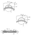
- Figs. 7 and 8 show a second embodiment B of a steel laminate type cylinder head gasket of the invention.
- the gasket B is formed of an upper plate B11, a first middle plate B12 with a hole B12a and an elongated portion B12d, a second or middle plate B13 with beads B13a, B13b, a middle plate B14, a lower plate B15, and a wire ring B16, as in the gasket A.
- the gasket B further includes an elongated curved member B19 situated on the elongated portion B12d to strengthen the elongated portion B12d.
- the elongated curved member B19 may be situated on a different place, such as under the bead B13a.
- the elongated curved member B19 is made of a thin metal plate and extends slightly beyond the mouth plate L.
- the elongated curved member B19, the elongated portion B12d, the wire ring B16 and a compressible sheet B18 support the mouth plate L.
- the gasket B operate as in the gasket A.
- Fig. 9 shows a third embodiment C of a steel laminate type cylinder head gasket of the invention.
- the gasket C is formed of an upper plate C11, three middle plates C12, C13, C14, a lower plate C15, and a wire ring C16, as in the gasket B.
- an annular ring C19 is situated above the elongated portion C12d to entirely surround the cylinder bore Hc.
- sealing ability around the cylinder bore Hc is improved.
- the gasket C operates as in the gasket B.
- Figs. 10 and 11 show a fourth embodiment D of a steel laminate type cylinder head gasket of the invention.
- the gasket D is formed of an upper plate D11, three middle plates D12, D13, D14, a lower plate D15, and a wire ring D16, as in the gasket A.
- the first middle plate D12 is provided with a hole or concave D12a surrounded by a line D12b only. Namely, there is no elongated portion, like the portion A12d as shown in Fig. 5. Instead, a thick metal member D20 is situated to separate the hole D12a from the cylinder bore Hc.
- the thick metal member D20, the wire ring D16 and a compressible sheet D18 support the mouth plate L.
- the gasket D operates as in the gasket A.
- a hole is formed adjacent to a cylinder bore, in which a compressible sheet is provided.
- a supporting member is formed in an elongated portion or a curved portion between the hole and the cylinder bore to support the mouth plate. Accordingly, force applied to the mouth plate is not concentrated on only one plate or portion, so that an outer plate of the gasket is not substantially damaged by the mouth plate.
Landscapes
- Engineering & Computer Science (AREA)
- General Engineering & Computer Science (AREA)
- Mechanical Engineering (AREA)
- Chemical & Material Sciences (AREA)
- Combustion & Propulsion (AREA)
- Gasket Seals (AREA)
Claims (12)
- Joint de tête de cylindre (A à C) du type en acier stratifié destiné à être installé dans un moteur à combustion interne entre un bloc cylindre (P) muni d'un alésage de cylindre (Hc) et une tête de cylindre (J) ayant une chambre de combustion auxiliaire (M), une plaque d'embouchure (L) étant fixée sur la tête de cylindre (J) pour fermer ladite chambre de combustion auxiliaire et étant partiellement supportée par une partie du joint, le joint (A à C) comportant:
une plaque supérieure (A11; B11; C11) ayant une partie incurvée vers le bas (A11a) entourant l'alésage de cylindre, une première plaque médiane (A12; B12; C12), et une seconde plaque (A13; B13),
des moyens d'étanchéité (A16; B16; C16) agencés dans la partie incurvée vers le bas (A11a) de ladite plaque supérieure pour entourer l'alésage de cylindre et assurer l'étanchéité dudit alésage,
la première plaque médiane (A12; B12; C12) s'étendant pratiquement sur toute la surface du joint, ladite première plaque médiane ayant un premier trou correspondant à l'alésage de cylindre (Hc) du moteur,
la seconde plaque (A13; B13; C13) étant adjacente sous ladite première plaque médiane, en ayant un trou correspondant à l'alésage de cylindre (Hc) et en ayant un bourrelet (A13a; B13a) s'étendant au moins partiellement autour de l'alésage de cylindre,
ledit joint (A à C) étant caractérisé en ce que:
la première plaque médiane (A12; B12; C12) comporte un second trou (A12a; B12a; C12a) adjacent au premier trou et situé sous une partie de la plaque d'emhouchure (L), ledit second trou étant défini par une première ligne extérieure incurvée (A12b) , adjacente au contour de la plaque d'embouchure et éloignée d'une distance prédéterminée de celle-ci et une seconde ligne intérieure (A12c) adjacente à l'alésage de cylindre et éloignée d'une distance prédéterminée de celui-ci pour former par conséquent une bande allongée (A12d; B12d; C12d) entre le premier et le second trous, la seconde plaque (A13; B13; C13) étant placée sous la première plaque médiane (A12; B12; C12),
un élément compressible (A18; B18) est placé dans le second trou (A12a; B12a; C12a) pour supporter la plaque d'embouchure et
ladite bande allongée (A12d; B12d; C12d), les moyens d'étanchéité (A16; B16; C16) et l'élément compressible (A18; B18) constituent des moyens pour supporter la plaque d'embouchure à proximité de l'alésage de cylindre. - Joint de tête de cylindre (A à C) du type en acier stratifié selon la revendication 1, caractérisé en ce que ledit bourrelet (A13a; B13a) de la seconde plaque (A13; B13; C13) est situé sous la bande allongée (A12d; B12d; C12d).
- Joint de tête de cylindre (A à C) du type en acier stratifié selon la revendication 1 ou 2, caractérisé en ce que ledit bourrelet (A13a; B13a) s'étend autour de la totalité de l'alésage de cylindre (Hc).
- Joint de tête de cylindre du type en acier stratifié selon l'une quelconque des revendications 1 à 3, caractérisé en ce que lesdits moyens d'étanchéité (A16; B16; C16) sont constitués d'un anneau de fil situé entre la partie incurvée (A11a) et la première plaque médiane (A12; B12; C12).
- Joint de tête de cylindre (B; C) du type en acier stratifié selon l'une quelconque des revendications 1 à 4, caractérisé en ce qu'il comporte en outre une plaque métallique mince (B19; C19) ayant une dimension au moins égale à la dimension de la bande allongée (B12d; C12d), ladite plaque métallique mince (B19; C19) étant stratifiée sur la bande allongée.
- Joint de tête de cylindre (C) du type en acier stratifié selon la revendication 5, caractérisé en ce que ladite plaque métallique mince (C19) s'étend autour de la totalité de l'alésage de cylindre (Hc).
- Joint de tête de cylindre (D) du type en acier stratifié destiné à être installé dans un moteur à combustion interne entre un bloc cylindre (P) muni d'un alésage de cylindre (Hc) et une tête de cylindre (J) ayant une chambre de combustion auxiliaire (M), une plaque d'embouchure (L) étant fixée sur la tête de cylindre (J) pour fermer ladite chambre de combustion auxiliaire et étant partiellement supportée par une partie du joint, le joint (D) comportant:
une plaque supérieure (D11) ayant une partie incurvée vers le bas entourant l'alésage de cylindre, une première plaque médiane (D12), et une seconde plaque (D13),
des moyens d'étanchéité (D16) agencés dans la partie incurvée vers le bas de ladite plaque supérieure pour entourer l'alésage de cylindre et assurer l'étanchéité dudit alésage,
la première plaque médiane (D12) s'étendant pratiquement sur toute la surface du joint, ladite première plaque médiane ayant un premier trou correspondant à l'alésage de cylindre (Hc) du moteur,
la seconde plaque (D13) étant adjacente sous ladite première plaque médiane, et ayant un trou correspondant à l'alésage de cylindre (Hc),
ledit joint (D) étant caractérisé en ce que:
ladite première plaque médiane (D12) comporte un creux concave (D12a) à proximité du premier trou sous une partie de la plaque d'embouchure (L), ledit creux concave (D12a) étant défini par une ligne extérieure incurvée (D12b), adjacente au contour de la plaque d'embouchure et éloignée d'une distance prédéterminée de celle-ci,
une bande allongée (D20) située au niveau de l'entrée du creux concave (D12a) de la première plaque médiane pour former un second trou dans la première plaque médiane, défini par la ligne extérieure incurvée (D12b) et une ligne extérieure de la bande allongée (D20) et séparé du premier trou,
un élément compressible (D18) est placé dans le second trou pour supporter la plaque d'embouchure (L) et
ladite bande allongée (D20), les moyens d'étanchéité (D16) et l'élément compressible (D18) constituent des moyens pour supporter la plaque d'embouchure à proximité de l'alésage de cylindre. - Joint de tête de cylindre (A à D) du type en acier stratifié selon l'une quelconque des revendications 1 à 7, caractérisé en ce que ledit élément compressible (A18 à D18) est constitué à base de graphite.
- Joint de tête de cylindre (A; B) du type en acier stratifié selon l'une quelconque des revendications 1 à 6, caractérisé en ce que ladite seconde plaque comporte un premier bourrelet (A13b; B13b) situé le long de la première ligne incurvée (A12b) et à une distance prédéterminée en s'éloignant vers l'extérieur à partir de celle-ci, et un second bourrelet (A13a; B13a) situé sous la bande allongée (A12d; B12d), ledit premier et ledit second bourrelets étant reliés mutuellement.
- Joint de tête de cylindre (A ;B) du type en acier stratifié selon la revendication 9, caractérisé en ce que ledit second bourrelet (A13a; B13a) s'étend autour de la totalité de l'alésage de cylindre.
- Joint de tête de cylindre (B; C) du type en acier stratifié selon la revendication 5 ou 6, caractérisé en ce que ladite seconde plaque (B13; C13) comporte un premier bourrelet (B13b) situé le long de la première ligne incurvée et à une distance prédéterminée en s'éloignant vers l'extérieur à partir de celle-ci, et un second bourrelet (B13a) situé sous la bande allongée (B12d; C12d), ledit second bourrelet et la plaque métallique mince (B19; C19), associés à la bande allongée, constituant les moyens de support de la plaque d'embouchure, lesdits premier et second bourrelets étant reliés mutuellement.
- Joint de tête de cylindre (D) du type en acier stratifié selon la revendication 7, caractérisé en ce que ladite bande allongée (D20) est formée de manière séparée de la première plaque médiane (D12) et est constituée d'une plaque métallique plus épaisse que ladite première plaque médiane.
Applications Claiming Priority (6)
| Application Number | Priority Date | Filing Date | Title |
|---|---|---|---|
| JP401396/90U | 1990-12-21 | ||
| JP401395/90U | 1990-12-21 | ||
| JP401397/90U | 1990-12-21 | ||
| JP40139590U JPH0714694Y2 (ja) | 1990-12-21 | 1990-12-21 | 副燃焼室付内燃機関用金属積層形ガスケット |
| JP40139790U JPH0714696Y2 (ja) | 1990-12-21 | 1990-12-21 | 副燃焼室付内燃機関用金属積層形ガスケット |
| JP1990401396U JPH0714695Y2 (ja) | 1990-12-21 | 1990-12-21 | 副燃焼室付内燃機関用金属積層形ガスケット |
Publications (2)
| Publication Number | Publication Date |
|---|---|
| EP0493954A1 EP0493954A1 (fr) | 1992-07-08 |
| EP0493954B1 true EP0493954B1 (fr) | 1995-04-12 |
Family
ID=27341893
Family Applications (1)
| Application Number | Title | Priority Date | Filing Date |
|---|---|---|---|
| EP19910311930 Expired - Lifetime EP0493954B1 (fr) | 1990-12-21 | 1991-12-23 | Joint de culasse en acier stratifié |
Country Status (3)
| Country | Link |
|---|---|
| EP (1) | EP0493954B1 (fr) |
| DE (1) | DE69108884T2 (fr) |
| ES (1) | ES2070449T3 (fr) |
Family Cites Families (3)
| Publication number | Priority date | Publication date | Assignee | Title |
|---|---|---|---|---|
| JPS5990745A (ja) * | 1982-11-16 | 1984-05-25 | Ishikawa Gasket Kk | 金属積層形ヘツドガスケツト |
| JPH025083Y2 (fr) * | 1986-07-07 | 1990-02-07 | ||
| JPH0313555Y2 (fr) * | 1987-04-21 | 1991-03-27 |
-
1991
- 1991-12-23 DE DE1991608884 patent/DE69108884T2/de not_active Expired - Fee Related
- 1991-12-23 EP EP19910311930 patent/EP0493954B1/fr not_active Expired - Lifetime
- 1991-12-23 ES ES91311930T patent/ES2070449T3/es not_active Expired - Lifetime
Also Published As
| Publication number | Publication date |
|---|---|
| DE69108884T2 (de) | 1995-08-24 |
| ES2070449T3 (es) | 1995-06-01 |
| DE69108884D1 (de) | 1995-05-18 |
| EP0493954A1 (fr) | 1992-07-08 |
Similar Documents
| Publication | Publication Date | Title |
|---|---|---|
| US4898396A (en) | Steel laminate gasket | |
| US5435575A (en) | Steel laminate gasket | |
| US4809653A (en) | Steel laminate type cylinder head gasket | |
| US5511796A (en) | Metal laminate gasket with sealing shim | |
| EP0500316B1 (fr) | Joint métalliques laminé à double anneaux d'étanchéité | |
| EP0468654B1 (fr) | Joint d'acier laminé avec éléments pour étanchéité principale et auxiliaire | |
| EP1387113B1 (fr) | Garniture métallique avec un joint circulaire | |
| EP0864785A2 (fr) | Joint métallique multicouches avec taille irrégulière de l'anneau d'étanchéité | |
| US5408963A (en) | Metal laminate gasket having sealing mechanism formed of recess and flange | |
| US5460387A (en) | Metal laminate gasket having sealing mechanism formed of recess and flange | |
| US5306023A (en) | Cylinder head gasket with auxiliary sealing plate | |
| EP0518665B1 (fr) | Joint métallique multicouche avec anneau d'étanchéité | |
| EP0518664A1 (fr) | Joint métallique lamifié avec bourrelet auxiliaire d'étanchéité | |
| EP0480606B1 (fr) | Joint d'étancheité en acier laminé pour culasse | |
| US5165372A (en) | Steel laminate type cylinder head gasket | |
| US5255927A (en) | Metal laminate type cylinder head gasket | |
| US5009438A (en) | Steel laminate gasket with associated beads | |
| EP0486150B1 (fr) | Joint d'étanchéité en acier laminé avec élément de protection | |
| US5899462A (en) | Metal laminate gasket with stepped sealing portion | |
| EP0431227B1 (fr) | Joint d'étanchéité en acier laminé | |
| EP0493954A1 (fr) | Joint de culasse en acier stratifié | |
| EP0713989B1 (fr) | Joint de culasse métallique laminé avec partie obturatrice de chaleur | |
| US5895055A (en) | Metal gasket with opposite flanges |
Legal Events
| Date | Code | Title | Description |
|---|---|---|---|
| PUAI | Public reference made under article 153(3) epc to a published international application that has entered the european phase |
Free format text: ORIGINAL CODE: 0009012 |
|
| 17P | Request for examination filed |
Effective date: 19920113 |
|
| AK | Designated contracting states |
Kind code of ref document: A1 Designated state(s): DE ES FR GB IT SE |
|
| 17Q | First examination report despatched |
Effective date: 19931029 |
|
| GRAA | (expected) grant |
Free format text: ORIGINAL CODE: 0009210 |
|
| AK | Designated contracting states |
Kind code of ref document: B1 Designated state(s): DE ES FR GB IT SE |
|
| ITF | It: translation for a ep patent filed | ||
| REF | Corresponds to: |
Ref document number: 69108884 Country of ref document: DE Date of ref document: 19950518 |
|
| ET | Fr: translation filed | ||
| REG | Reference to a national code |
Ref country code: ES Ref legal event code: FG2A Ref document number: 2070449 Country of ref document: ES Kind code of ref document: T3 |
|
| PLBE | No opposition filed within time limit |
Free format text: ORIGINAL CODE: 0009261 |
|
| STAA | Information on the status of an ep patent application or granted ep patent |
Free format text: STATUS: NO OPPOSITION FILED WITHIN TIME LIMIT |
|
| 26N | No opposition filed | ||
| PGFP | Annual fee paid to national office [announced via postgrant information from national office to epo] |
Ref country code: SE Payment date: 19981127 Year of fee payment: 8 |
|
| PGFP | Annual fee paid to national office [announced via postgrant information from national office to epo] |
Ref country code: DE Payment date: 19981130 Year of fee payment: 8 |
|
| PGFP | Annual fee paid to national office [announced via postgrant information from national office to epo] |
Ref country code: GB Payment date: 19981203 Year of fee payment: 8 |
|
| PGFP | Annual fee paid to national office [announced via postgrant information from national office to epo] |
Ref country code: ES Payment date: 19981204 Year of fee payment: 8 |
|
| PGFP | Annual fee paid to national office [announced via postgrant information from national office to epo] |
Ref country code: FR Payment date: 19981230 Year of fee payment: 8 |
|
| PG25 | Lapsed in a contracting state [announced via postgrant information from national office to epo] |
Ref country code: GB Free format text: LAPSE BECAUSE OF NON-PAYMENT OF DUE FEES Effective date: 19991223 |
|
| PG25 | Lapsed in a contracting state [announced via postgrant information from national office to epo] |
Ref country code: SE Free format text: LAPSE BECAUSE OF NON-PAYMENT OF DUE FEES Effective date: 19991224 |
|
| EUG | Se: european patent has lapsed |
Ref document number: 91311930.1 |
|
| GBPC | Gb: european patent ceased through non-payment of renewal fee |
Effective date: 19991223 |
|
| PG25 | Lapsed in a contracting state [announced via postgrant information from national office to epo] |
Ref country code: FR Free format text: LAPSE BECAUSE OF NON-PAYMENT OF DUE FEES Effective date: 20000831 |
|
| PG25 | Lapsed in a contracting state [announced via postgrant information from national office to epo] |
Ref country code: DE Free format text: LAPSE BECAUSE OF NON-PAYMENT OF DUE FEES Effective date: 20001003 |
|
| REG | Reference to a national code |
Ref country code: FR Ref legal event code: ST |
|
| PG25 | Lapsed in a contracting state [announced via postgrant information from national office to epo] |
Ref country code: ES Free format text: LAPSE BECAUSE OF NON-PAYMENT OF DUE FEES Effective date: 20001224 |
|
| REG | Reference to a national code |
Ref country code: ES Ref legal event code: FD2A Effective date: 20010113 |
|
| PG25 | Lapsed in a contracting state [announced via postgrant information from national office to epo] |
Ref country code: IT Free format text: LAPSE BECAUSE OF NON-PAYMENT OF DUE FEES;WARNING: LAPSES OF ITALIAN PATENTS WITH EFFECTIVE DATE BEFORE 2007 MAY HAVE OCCURRED AT ANY TIME BEFORE 2007. THE CORRECT EFFECTIVE DATE MAY BE DIFFERENT FROM THE ONE RECORDED. Effective date: 20051223 |