EP0494092A2 - Méthode et dispositif pour éliminer dans l'eau des obstacles pour la navigation - Google Patents
Méthode et dispositif pour éliminer dans l'eau des obstacles pour la navigation Download PDFInfo
- Publication number
- EP0494092A2 EP0494092A2 EP92104957A EP92104957A EP0494092A2 EP 0494092 A2 EP0494092 A2 EP 0494092A2 EP 92104957 A EP92104957 A EP 92104957A EP 92104957 A EP92104957 A EP 92104957A EP 0494092 A2 EP0494092 A2 EP 0494092A2
- Authority
- EP
- European Patent Office
- Prior art keywords
- vehicle
- water
- navigational
- platform
- imaging sensor
- Prior art date
- Legal status (The legal status is an assumption and is not a legal conclusion. Google has not performed a legal analysis and makes no representation as to the accuracy of the status listed.)
- Granted
Links
Images


Classifications
-
- B—PERFORMING OPERATIONS; TRANSPORTING
- B63—SHIPS OR OTHER WATERBORNE VESSELS; RELATED EQUIPMENT
- B63G—OFFENSIVE OR DEFENSIVE ARRANGEMENTS ON VESSELS; MINE-LAYING; MINE-SWEEPING; SUBMARINES; AIRCRAFT CARRIERS
- B63G7/00—Mine-sweeping; Vessels characterised thereby
-
- F—MECHANICAL ENGINEERING; LIGHTING; HEATING; WEAPONS; BLASTING
- F41—WEAPONS
- F41G—WEAPON SIGHTS; AIMING
- F41G7/00—Direction control systems for self-propelled missiles
- F41G7/20—Direction control systems for self-propelled missiles based on continuous observation of target position
- F41G7/30—Command link guidance systems
- F41G7/301—Details
- F41G7/303—Sighting or tracking devices especially provided for simultaneous observation of the target and of the missile
-
- F—MECHANICAL ENGINEERING; LIGHTING; HEATING; WEAPONS; BLASTING
- F41—WEAPONS
- F41G—WEAPON SIGHTS; AIMING
- F41G7/00—Direction control systems for self-propelled missiles
- F41G7/20—Direction control systems for self-propelled missiles based on continuous observation of target position
- F41G7/30—Command link guidance systems
- F41G7/301—Details
- F41G7/306—Details for transmitting guidance signals
-
- F—MECHANICAL ENGINEERING; LIGHTING; HEATING; WEAPONS; BLASTING
- F41—WEAPONS
- F41G—WEAPON SIGHTS; AIMING
- F41G7/00—Direction control systems for self-propelled missiles
- F41G7/20—Direction control systems for self-propelled missiles based on continuous observation of target position
- F41G7/30—Command link guidance systems
- F41G7/32—Command link guidance systems for wire-guided missiles
-
- F—MECHANICAL ENGINEERING; LIGHTING; HEATING; WEAPONS; BLASTING
- F41—WEAPONS
- F41G—WEAPON SIGHTS; AIMING
- F41G9/00—Systems for controlling missiles or projectiles, not provided for elsewhere
- F41G9/008—Means for controlling firing of torpedoes; Torpedo directors
-
- F—MECHANICAL ENGINEERING; LIGHTING; HEATING; WEAPONS; BLASTING
- F42—AMMUNITION; BLASTING
- F42B—EXPLOSIVE CHARGES, e.g. FOR BLASTING, FIREWORKS, AMMUNITION
- F42B19/00—Marine torpedoes, e.g. launched by surface vessels or submarines; Sea mines having self-propulsion means
- F42B19/01—Steering control
- F42B19/10—Steering control remotely controlled, e.g. by sonic or radio control
-
- F—MECHANICAL ENGINEERING; LIGHTING; HEATING; WEAPONS; BLASTING
- F42—AMMUNITION; BLASTING
- F42B—EXPLOSIVE CHARGES, e.g. FOR BLASTING, FIREWORKS, AMMUNITION
- F42B19/00—Marine torpedoes, e.g. launched by surface vessels or submarines; Sea mines having self-propulsion means
- F42B19/46—Marine torpedoes, e.g. launched by surface vessels or submarines; Sea mines having self-propulsion means adapted to be launched from aircraft
Definitions
- This invention relates generally to a sensor system for remote detection and imaging of objects submerged underwater and an underwater vehicle guided by the sensor system for removing submerged navigational hazards. More particularly, this invention relates to a method and apparatus for detecting, locating, imaging and removing (e.g., destroying) underwater objects such as mines by use of an underwater self-propelled vehicle which is guided from an airborne platform using a novel imaging lidar (light detection and ranging) system.
- a novel imaging lidar light detection and ranging
- wire line devices Presently, cumbersome and time consuming wire line devices must be used for detecting underwater targets from remote airborne locations. These devices are lowered into the water and of course, are easily subject to damage and loss. Also, wire line devices make target searching relatively slow and can only detect targets without providing visual imaging.
- U.S. Patent 4,862,257 and U.S. Patent 5,013,917 both of which are assigned to the assignee hereof and incorporated herein by reference.
- the imaging lidar system of U.S. Patent 4,862,257 utilizes a laser to generate short pulses of light with pulse widths on the order of nanoseconds. The laser light is expanded by optics and projected down toward the surface of the water and to an object or target.
- U.S. Patent 5,013,917 relates to an imaging lidar system intended for night vision.
- Patent 4,964,721 relates to an imaging lidar system which controls camera gating based on input from the aircraft on-board altimeter and uses a computer to thereby adjust total time delay so as to automatically track changing platform altitude.
- Patent 4,967,270 relates to a lidar system employing a plurality of gated cameras which are individually triggered after preselected time delays to obtain multiple subimages laterally across a target image. These multiple subimages are then put together in a mosaic in a computer to provide a complete image of a target plane preferably using only a single light pulse.
- USSN 565,631 filed August 10, 1990 which is also assigned to the assignee hereof and fully incorporated herein by reference, relates to an airborne imaging lidar system which employs a plurality of pulsed laser transmitters, a plurality of gated and intensified array camera receivers, an optical scanner for increased field of regard, and a computer for system control, automatic target detection and display generation.
- USSN 565,631 provides a means for rapidly searching a large volume of the backscattering medium (e.g., water) for specified targets and improves upon prior art devices in performance as a result of having more energy in each laser pulse (due to simultaneous operation of multiple lasers) and a more sensitive detection system using multiple cameras.
- the backscattering medium e.g., water
- the several cameras may be utilized to image different range gates on a single laser pulse or several cameras can be gated on at the same time to provide independent pictures which can then be averaged to reduce the noise level and improve sensitivity. Both of these improvements result in higher signal-to-noise ratio and thus higher probability of detection or greater range of depth capability.
- the present invention comprises an air launched submersible vehicle which can be launched, for example, from the sonobuoy carrying racks of a rotary wing aircraft (or any other suitable airborne platform).
- the submersible vehicle Upon identification and classification of the target by the imaging lidar system, the submersible vehicle is ejected from the carrying rack upon command. A vehicle drogue parachute is then deployed. Upon impact with the water, guidance is activated and the high explosive charge is fully armed.
- This vehicle (now in the water) is provided the depth of the target and leaves a trailing wire or buoy afloat for communications (or alternatively uses a raised antenna which extends above the water line); and is initially guided to the vicinity of the target automatically by radio signals from the computer associated with the imaging lidar system.
- the underwater vehicle can be hardwired directly to the airborne platform using a fiber optic cable.
- the vehicle is then guided to the target by the same signals transmitted through the trailing wire antenna. The vehicle automatically maintains the depth of the target making the homing problem two dimensional.
- the imaging computer (associated with the imaging lidar system on-board the airborne platform) uses the vehicle's motion relative to the fixed target (eliminating the effects of imaging platform motion) to determine its course.
- the relative location of the two objects is used to determine the required course for intercept.
- the difference between actual and required courses will be corrected by the computer's issuance of a steering command to the left or right for the appropriate number of seconds.
- required and actual courses will be recomputed and the process repeated.
- Detonation of the explosive payload is also preferably controlled by the computer on-board the airborne platform.
- the computer can determine the closest point of approach and send a detonation signal accordingly. Should the closest point of approach be beyond the "assured kill" radius, no detonation signal will be sent.
- the vehicle will simply pass by the target and automatically reengage as new required courses are computed and steering commands issued.
- a contact fuse may also detonate the vehicle on impact with the target. Should the vehicle fail to make "contact” with the target and thus fail to detonate, the high expolsive may then be detonated by a salvage fuzing at the end of its propulsion cycle or after passing below a preselected depth.
- the video console operator expands the field of his target image until the vehicle is detected. At this time, the console operator activates depth ontrol, which automatically positions the vehicle at the depth of the target.
- Guidance consists of sequential commands to the vehicle rudder. Upon approach to the target, a high explosive or shaped charge is detonated on command from the console operator, thereby destroying the target.
- Either shaped charges or insensitive high explosive charges are used, depending on the nature of the target.
- the vehicle When the target is floating, the vehicle is set for positive buoyancy, eliminating the need for internal independent depth control.
- a small pop-up antenna can be used for surface deployment to receive the guidance and destruct signals, eliminating the need for the trailing antenna.
- the present invention comprises an underwater maneuverable vehicle which carries an explosive charge and is used for immediate removal or destruction of various menaces to navigation and other underwater hazards.
- the battery powered vehicle is air dropped from a platform (e.g., helicopter) which carries an imaging lidar system for detection of the underwater hazard.
- the underwater vehicle is operated and navigationally controlled in conjunction with the lidar system.
- the submerged maneuverable vehicle may also be navigationally controlled by imaging sonar or a similar imaging system.
- TABLE 1 Two principal operating modes are shown in TABLE 1 including (1) the surface mode where floating obstructions are encountered and destroyed; and (2) the underwater mode where targets floating, bottomed or moored a significant distance below the water must be removed.
- the surface mode of operation (FIGURES 1A-IF and 2), console settings are initially provided for flooding, fusing and antenna deployment. The vehicle is then released from the platform and is slowed before entry to the water by a small drogue parachute, which is detached upon water entry.
- a small pop-up antenna is deployed and the vehicle propulsion motor is activated. Immediate activation is not necessary, as propulsion for depth control is not required.
- the flooding ballast approach will not be used but rather, the automatic depth control will be set to maintain the vehicle at or slightly below the surface for all target depths.
- the propulsion motor is activated on command and guided to the vicinity of the target. Guidance is accomplished automatically by the imaging computer or manually with the operator observing the image of the target and the vehicle on the video screen of the lidar system and manually guiding the vehicle to the vicinity of the target.
- the explosive or shaped charge is detonated by computer signal or operator command. Additional instruction may be used for correct orientation of a shaped charge, particularly at depths below the surface.
- the vehicle flooding ports remain open, and the depth of the target is set in.
- the depth is determined from the imaging lidar; it is set at the depth where the target becomes obscuring, rather than reflective.
- the vehicle is launched, the drogue chute is deployed and the vehicle enters the water.
- the free flooding area is flooded, since the ports have not been closed, and the vehicle now has slightly negative buoyancy.
- the vehicle begins to swim downward, with the explosive fusing some ten feet above the set depth.
- the floating wire antenna is deployed.
- the vehicle is guided in azimuth as before, with a horizontal stabilizer providing depth control.
- the free flooding ports (if this option is used) are closed, so that the vehicle retains positive buoyancy.
- the video presentation the vehicle is guided to the target as before by RF signals received through the floating antenna.
- the explosive charge is detonated at the time the operator sees the vehicle approach the target closely enough for it to break up.
- FIGURES 1A-F the above-described sequence for vehicle launch against a surface target is shown.
- a submersible vehicle 10 in accordance with the present invention is shown mounted on a platform 12 attached to a rack 14 by clamps 16.
- an umbilical cord 18 which communicates with an on-board command computer associated with an imaging lidar system (which is also on-board platform 12).
- an imaging lidar system which is also on-board platform 12.
- FIGURE 1B clamps 16 have released, vehicle 10 has left rack 14, the umbilical cord 18 is detached and a drogue chute 20 is beginning to deploy as the vehicle approaches water 22 on which a target 24 is floating.
- drogue chute 20 is not fully deployed, slowing the fall of the vehicle to the water surface.
- the console settings (see FIGURE 5) are for deployment of a pop-up antenna 26. Therefore, no depth control, closure of the flooding ports, and fusing are required to set on water entry.
- FIGURE 1D vehicle 10 has entered water 22 and shed the drogue chute 20. Pop-up antenna 26 is in place and ready to receive rf signals.
- FIGURE 1E shows vehicle 10 under power via propeller 28 receiving rf steering commands 30 from the console operator who now views both target 24 and vehicle 10 images on a real time video screen as will be shown in FIGURE 2.
- a detonation command 32 has been sent, the explosive or shaped charge has exploded at 34 and the target 24 has been destroyed.
- the console operator then observes the debris or fragments of target 24 as they slowly disperse, indicating the complete destruction of the navigational hazard.
- any suitable imaging sensor may be used to control and simultaneously view the underwater vehicle and the target.
- suitable imaging sensors include imaging lidar systems and imaging sonar systems.
- an imaging lidar system of the type discussed in the Background Section (such as U.S. Patent Nos. 4,862,257, 4,964,721, 4,967,270, 5,013,917, 5,029,009, 5,034,810 or USSN 565,631) is employed in the present invention.
- imaging systems of this type image a volume of water using a pulsed laser transmitter in combination with one or more gated cameras.
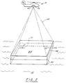
- an airborne platform e.g., helicopter 12 is shown having an imaging lidar system 36 of the aforementioned type positioned on-board.
- the lidar imaging system is shown having detected the target 24, determined it to be on the surface 38 of water 12, and is now imaging both the vehicle 10 and the target 24.
- the illumination 40 from the laser transmitter 42 covers a rectangular area 44 and is gated below the water surface so that the illumination of the underwater region or volume 46 is achieved. Since gated region 46 of illumination is below both target 24 and vehicle 10, both appear as shadows on the video console.
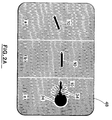
- FIGURE 2A sequential depictions are shown (at (a), (b) and (c)), as seen from the console 48 in the platform 12, the vehicle 10 (seen in shadow) is being guided to the target 24 (also seen in shadow) with the console operator sending the appropriate guidance signals to provide course corrections. (These signals are sent to a servo system 48 which operates a vertical rudder 50 shown in FIGURE 6).
- sequence (c) of FIGURE 2A the vehicle 10 has approached the target sufficiently closely so that the explosive charge is detonated (at 34) thereby destroying the target 24 which then sinks to the bottom of the body of water 22.
- FIGURES 3 and 4 the approach to and destruction of a submerged target (as opposed to the floating target 24 of FIGURE 1) is shown.
- the imaging lidar system has detected a submerged target 58 in the submerged target option.
- the free space in the vehicle Upon entry into the water 22, the free space in the vehicle will flood causing it to have slightly negative buoyancy and the depth control option will now take over with target depth preset by the console operator.
- a floating antenna 54 deploys after water entry.
- FIGURE 3A the drogue chute 20 is fully deployed as the vehicle 10 falls toward the water.
- the vehicle 10 sheds the drogue chute 20 and commences deployment of the floating wire antenna 54.
- the pop-up antenna 26 shown previously in FIGURE 1, can be deployed or remain housed.
- vehicle 10 In FIGURE 3B it has remained housed.
- vehicle 10 In FIGURE 3C, vehicle 10 is proceeding downward to target depth, driven by its negative buoyancy and the downward thrust provided by its propellers and the pitch of the horizontal stabilizers 56.
- the floating antenna 54 is now fully deployed and receiving guidance signals from the platform 12, activating the servo system 48 and moving the rudder 50.
- vehicle 10 is at the preset (target) depth, has levelled off and is now within close range of the target 58.
- the console operator sends the detonation signal 60, and in a short time target 58 will be destroyed.
- detonation can take place automatically by computer recognition of the closest point of approach or by direct contact.
- FIGURE 4A shows the target 58, platform 12 and vehicle 10 configuration during the submerged approach.
- the vehicle 10 has reached target depth 52 and is maintained at that depth by the automatic depth control servo system which controls the horizontal stabilizers.
- the floating wire antenna 54 has been deployed and is receiving rf signals (originated by the console operator) from the platform 12.
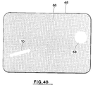
- the imaging lidar system 36 is illuminating an area 60 on the ocean surface and the receiving cameras are gated to view the illuminated region 62.
- the top of this region 64 is somewhat closer to the surface of the water than the vehicle 10 and target 58; and it is less than the target depth 52.
- the bottom 66 of the region 62 is below both target 58 and vehicle 10.
- the region 62 viewed includes both target 58 and vehicle 10, and they are seen in reflection. This is shown in the video image depicted in FIGURE 4B.
- the target 58 and vehicle 10 appear as bright objects against the gray background 68.
- the console operator's view is shown in FIGURE 5.
- the video console 69 is positioned in front of the operator from which the operator can see both vehicle 10 and target 24 or 58. Early detection of the vehicle is enchanced by the opening of the drogue chute 20, which is optically opaque, and is readily seen on the screen 48.
- To the right of the screen is the control panel 70.
- the surface and underwater settings automatically activate (or deactivate) depth control, flooding, etc., as discussed previously.
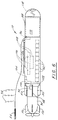
- FIGURE 6 is a detailed schematic of the vehicle 10 and the vehicle housing 88.
- Propulsion is provided by an 18 pounds of thrust trolling motor 90 (12 VDL, 28A) driven by a bank of 12V 30A lithium batteries 92.
- Motor 90 runs continuously upon water entry.
- the rf signals 94 are received by the antenna 26 or 54 and travel to the receiver 96 and then to the software/control module 98 which provides commands to the servo control 48.
- the servo control 48 then controls the vertical rudder 50 thereby steering the vehicle.
- a piezoelectric depth transducer 100 provides its input 102 to the software control module 98. This indication of depth is used by the software control system to control vehicle depth with the servo system 48 operating the horizontal stabilizers 56.
- the umbilical fitting 104 provides input to the control unit 98, providing the initial settings for underwater or surface operation.
- the control unit 98 also operates the ports 106 to the free flooding space 108 (again depending on the mode of operation). As mentioned earlier, ports 106 (if used) are closed for surface operation.
- the surface of the vehicle is preferably at least partially covered by a bright Lambertian reflecting paint so it can be easily imaged down to the required depth, but not so bright as to interfere with the imaging lidar camera gain control.
- the high explosive 110 in the form of a charge or shaped charge can be detonated on command, or by a contact influence fuse 112 as shown.
- housing 88 has a lengthy of 36 inches and a height of 4-7/8 inches; these dimensions being compatible with presently existing carriers found on rotary wing aircraft.
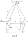
- FIGURE 7 is a schematic of the present invention similar to FIGURE 4A with the significant exception that imaging lidar system 36 is hardwired directly to vehicle 10 using fiber optic cable 120.
- Use of hardwired cable 120 eliminates the need for either pop-up antenna 26 (see FIGURE 2) or floating wire antenna 54 (see FIGURE 4A).
- the use of fiber optic communication leads to many important advantages and benefits. For example, fiber optics permits (1) faster data rates, (2) covert communications and (3) may eliminate the need for an on-board computer (e.g., control module 98 in FIGURE 6).
Landscapes
- Engineering & Computer Science (AREA)
- General Engineering & Computer Science (AREA)
- Chemical & Material Sciences (AREA)
- Combustion & Propulsion (AREA)
- Aviation & Aerospace Engineering (AREA)
- Control Of Position, Course, Altitude, Or Attitude Of Moving Bodies (AREA)
- Secondary Cells (AREA)
- Optical Radar Systems And Details Thereof (AREA)
- Cleaning In General (AREA)
Applications Claiming Priority (4)
| Application Number | Priority Date | Filing Date | Title |
|---|---|---|---|
| US74664591A | 1991-08-16 | 1991-08-16 | |
| US746645 | 1991-08-16 | ||
| US07/760,872 US5248978A (en) | 1991-08-16 | 1991-09-16 | Underwater guide vehicle for removal of submerged and floating navigational hazards |
| US760872 | 1991-09-16 |
Publications (3)
| Publication Number | Publication Date |
|---|---|
| EP0494092A2 true EP0494092A2 (fr) | 1992-07-08 |
| EP0494092A3 EP0494092A3 (en) | 1993-06-16 |
| EP0494092B1 EP0494092B1 (fr) | 1996-09-11 |
Family
ID=27114628
Family Applications (1)
| Application Number | Title | Priority Date | Filing Date |
|---|---|---|---|
| EP92104957A Expired - Lifetime EP0494092B1 (fr) | 1991-08-16 | 1992-03-23 | Méthode et dispositif pour éliminer dans l'eau des obstacles pour la navigation |
Country Status (4)
| Country | Link |
|---|---|
| US (1) | US5248978A (fr) |
| EP (1) | EP0494092B1 (fr) |
| AT (1) | ATE142576T1 (fr) |
| DE (1) | DE69213481D1 (fr) |
Cited By (6)
| Publication number | Priority date | Publication date | Assignee | Title |
|---|---|---|---|---|
| EP0775629A1 (fr) * | 1995-11-24 | 1997-05-28 | DIEHL GMBH & CO. | Méthode pour le dragage des mines marines |
| FR2751425A1 (fr) * | 1996-07-19 | 1998-01-23 | Thomson Marconi Sonar Sas | Procede et dispositif de lutte heliportee contre les mines sous-marines |
| EP0807572A3 (fr) * | 1996-05-15 | 1999-05-19 | Diehl Stiftung & Co. | Dispositif pour la destruction de mines à la dérive |
| US6509862B2 (en) * | 2001-01-18 | 2003-01-21 | Eads Deutschland Gmbh | Method of signal treatment and processing using the ROSAR system |
| DE102009040152A1 (de) * | 2009-05-02 | 2010-11-04 | Atlas Elektronik Gmbh | Verfahren zum Steuern eines Torpedos, Torpedo hierfür sowie Antennensektion eines derartigen Torpedos |
| DE102012006566A1 (de) * | 2012-03-30 | 2013-10-02 | Atlas Elektronik Gmbh | Verfahren zur Detektion von Seeminen und Seeminendetektionssystem |
Families Citing this family (9)
| Publication number | Priority date | Publication date | Assignee | Title |
|---|---|---|---|---|
| US5442358A (en) * | 1991-08-16 | 1995-08-15 | Kaman Aerospace Corporation | Imaging lidar transmitter downlink for command guidance of underwater vehicle |
| US5690041A (en) * | 1995-10-11 | 1997-11-25 | The United States Of America As Represented By The Secretary Of The Navy | Unmanned undersea vehicle system for weapon deployment |
| US5675116A (en) * | 1995-10-11 | 1997-10-07 | The United States Of America As Represented By The Secretary Of The Navy | Unmanned undersea vehicle including keel-mounted payload deployment arrangement with payload compartment flooding arrangement to maintain axi-symmetrical mass distribution |
| US5786545A (en) * | 1995-10-11 | 1998-07-28 | The United States Of America As Represented By The Secretary Of The Navy | Unmanned undersea vehicle with keel-mounted payload deployment system |
| US5704309A (en) * | 1995-12-06 | 1998-01-06 | Seamagine Hydrospace Corporation | Hybrid boat and underwater watercraft |
| US6668218B1 (en) | 2002-03-27 | 2003-12-23 | Lockheed Martin Corporation | Method and system for target localization |
| US8170272B1 (en) * | 2010-02-23 | 2012-05-01 | The United States Of America As Represented By The Secretary Of The Navy | Method for classifying vessels using features extracted from overhead imagery |
| JP2013117362A (ja) * | 2011-12-05 | 2013-06-13 | Kawasaki Heavy Ind Ltd | 飛しょう体の誘導システム |
| RU2662323C1 (ru) * | 2017-08-15 | 2018-07-25 | Федеральное государственное унитарное предприятие "Крыловский государственный научный центр" | Способ поиска подводных объектов подо льдом и устройство для его осуществления |
Family Cites Families (11)
| Publication number | Priority date | Publication date | Assignee | Title |
|---|---|---|---|---|
| US5012717A (en) * | 1964-09-29 | 1991-05-07 | The United States Of America As Represented By The Secretary Of The Navy | Air-to-subsurface missile system |
| US4030096A (en) * | 1975-12-05 | 1977-06-14 | Westinghouse Electric Corporation | Automatic target detector |
| US4088978A (en) * | 1976-09-27 | 1978-05-09 | Westinghouse Electric Corp. | Synthetic aperture side-looking sonar system |
| DE2839312C1 (de) * | 1978-09-09 | 1985-12-05 | Licentia Patent-Verwaltungs-Gmbh, 6000 Frankfurt | Anordnung zur UEbermittlung von Signalen zwischen zwei Schwimmkoerpern |
| DE2918128C1 (fr) * | 1979-05-07 | 1988-11-10 | Licentia Patent-Verwaltungs-Gmbh, 6000 Frankfurt, De | |
| US4802148A (en) * | 1982-11-08 | 1989-01-31 | Westinghouse Electric Corp. | Side-looking sonar apparatus |
| US4912685A (en) * | 1988-11-30 | 1990-03-27 | Westinghouse Electric Corp. | Side looking sonar apparatus |
| DE3932548A1 (de) * | 1989-09-29 | 1991-04-11 | Telefunken Systemtechnik | Verfahren und vorrichtung fuer eine torpedozielsteuerung |
| US5022015A (en) * | 1990-06-04 | 1991-06-04 | Westinghouse Electric Corp. | Sonar system of the type using hollow conical beams |
| US5042942A (en) * | 1990-07-25 | 1991-08-27 | Westinghouse Electric Corp. | Laser location apparatus for underwater bodies |
| US5043951A (en) * | 1990-08-01 | 1991-08-27 | Westinghouse Electric Corp. | Apparatus for reduction of side lobes in a beam pattern of an array |
-
1991
- 1991-09-16 US US07/760,872 patent/US5248978A/en not_active Expired - Lifetime
-
1992
- 1992-03-23 AT AT92104957T patent/ATE142576T1/de active
- 1992-03-23 EP EP92104957A patent/EP0494092B1/fr not_active Expired - Lifetime
- 1992-03-23 DE DE69213481T patent/DE69213481D1/de not_active Expired - Lifetime
Cited By (9)
| Publication number | Priority date | Publication date | Assignee | Title |
|---|---|---|---|---|
| EP0775629A1 (fr) * | 1995-11-24 | 1997-05-28 | DIEHL GMBH & CO. | Méthode pour le dragage des mines marines |
| EP0807572A3 (fr) * | 1996-05-15 | 1999-05-19 | Diehl Stiftung & Co. | Dispositif pour la destruction de mines à la dérive |
| DE19619571B4 (de) * | 1996-05-15 | 2004-04-22 | Diehl Stiftung & Co.Kg | Verfahren zur Vernichtung von Treibminen |
| FR2751425A1 (fr) * | 1996-07-19 | 1998-01-23 | Thomson Marconi Sonar Sas | Procede et dispositif de lutte heliportee contre les mines sous-marines |
| WO1998003883A1 (fr) * | 1996-07-19 | 1998-01-29 | Thomson Marconi Sonar S.A.S. | Procede et dispositif de lutte heliportee contre les mines sous-marines |
| US6509862B2 (en) * | 2001-01-18 | 2003-01-21 | Eads Deutschland Gmbh | Method of signal treatment and processing using the ROSAR system |
| DE102009040152A1 (de) * | 2009-05-02 | 2010-11-04 | Atlas Elektronik Gmbh | Verfahren zum Steuern eines Torpedos, Torpedo hierfür sowie Antennensektion eines derartigen Torpedos |
| WO2010127953A1 (fr) | 2009-05-02 | 2010-11-11 | Atlas Elektronik Gmbh | Procédé de guidage d'au moins une torpille, torpille pour ce procédé, ainsi que section antenne d'une telle torpille |
| DE102012006566A1 (de) * | 2012-03-30 | 2013-10-02 | Atlas Elektronik Gmbh | Verfahren zur Detektion von Seeminen und Seeminendetektionssystem |
Also Published As
| Publication number | Publication date |
|---|---|
| DE69213481D1 (de) | 1996-10-17 |
| EP0494092A3 (en) | 1993-06-16 |
| EP0494092B1 (fr) | 1996-09-11 |
| US5248978A (en) | 1993-09-28 |
| ATE142576T1 (de) | 1996-09-15 |
Similar Documents
| Publication | Publication Date | Title |
|---|---|---|
| US5442358A (en) | Imaging lidar transmitter downlink for command guidance of underwater vehicle | |
| US5241314A (en) | Image lidar transmitter downlink for command guidance of underwater vehicle | |
| US6359834B1 (en) | Mine neutralization device | |
| US5248978A (en) | Underwater guide vehicle for removal of submerged and floating navigational hazards | |
| US6082675A (en) | Standoff delivered sonobuoy | |
| EP0535044B2 (fr) | Procede et dispositif de detection d'un objet | |
| US5844159A (en) | Method and system for destroying submerged objects, in particular submerged mines | |
| US5012717A (en) | Air-to-subsurface missile system | |
| US6293202B1 (en) | Precision, airborne deployed, GPS guided standoff torpedo | |
| US6766745B1 (en) | Low cost rapid mine clearance system | |
| US6484660B1 (en) | Underwater nuclear material reconnaissance system | |
| US6366533B1 (en) | Underwater reconnaissance and surveillance system | |
| US4200922A (en) | Self-propelled vehicle for destroying ground mines | |
| US6498767B2 (en) | Cruise missile deployed sonar buoy | |
| RU2554640C2 (ru) | Способ обнаружения морских целей | |
| US3180295A (en) | Submarine simulator | |
| RU2269449C1 (ru) | Способ защиты охраняемой акватории от подводных диверсантов и устройство для его осуществления | |
| US4975888A (en) | Mine neutralization system | |
| US4903246A (en) | Minehunting systems | |
| CN112572738A (zh) | 小型水下无人光纤线轴遥控未爆危险物处理系统及方法 | |
| US5973994A (en) | Surface launched sonobuoy | |
| JP5155511B2 (ja) | 水中の物体を破壊するための装置 | |
| RU2670192C1 (ru) | Подводный аппарат для уничтожения потенциально опасного стационарного объекта | |
| US7752990B2 (en) | Device for destroying subsea or floating objects | |
| EP0426726B1 (fr) | Procede et dispositif de reperage et de destruction de sous-marins depuis un aeronef |
Legal Events
| Date | Code | Title | Description |
|---|---|---|---|
| PUAI | Public reference made under article 153(3) epc to a published international application that has entered the european phase |
Free format text: ORIGINAL CODE: 0009012 |
|
| AK | Designated contracting states |
Kind code of ref document: A2 Designated state(s): AT BE CH DE DK ES FR GB GR IT LI LU MC NL PT SE |
|
| PUAL | Search report despatched |
Free format text: ORIGINAL CODE: 0009013 |
|
| AK | Designated contracting states |
Kind code of ref document: A3 Designated state(s): AT BE CH DE DK ES FR GB GR IT LI LU MC NL PT SE |
|
| 17P | Request for examination filed |
Effective date: 19931022 |
|
| 17Q | First examination report despatched |
Effective date: 19950112 |
|
| GRAH | Despatch of communication of intention to grant a patent |
Free format text: ORIGINAL CODE: EPIDOS IGRA |
|
| GRAH | Despatch of communication of intention to grant a patent |
Free format text: ORIGINAL CODE: EPIDOS IGRA |
|
| GRAA | (expected) grant |
Free format text: ORIGINAL CODE: 0009210 |
|
| AK | Designated contracting states |
Kind code of ref document: B1 Designated state(s): AT BE CH DE DK ES FR GB GR IT LI LU MC NL PT SE |
|
| PG25 | Lapsed in a contracting state [announced via postgrant information from national office to epo] |
Ref country code: NL Free format text: LAPSE BECAUSE OF FAILURE TO SUBMIT A TRANSLATION OF THE DESCRIPTION OR TO PAY THE FEE WITHIN THE PRESCRIBED TIME-LIMIT Effective date: 19960911 Ref country code: LI Effective date: 19960911 Ref country code: GR Free format text: LAPSE BECAUSE OF FAILURE TO SUBMIT A TRANSLATION OF THE DESCRIPTION OR TO PAY THE FEE WITHIN THE PRESCRIBED TIME-LIMIT Effective date: 19960911 Ref country code: FR Effective date: 19960911 Ref country code: ES Free format text: THE PATENT HAS BEEN ANNULLED BY A DECISION OF A NATIONAL AUTHORITY Effective date: 19960911 Ref country code: DK Effective date: 19960911 Ref country code: CH Effective date: 19960911 Ref country code: BE Effective date: 19960911 Ref country code: AT Effective date: 19960911 |
|
| REF | Corresponds to: |
Ref document number: 142576 Country of ref document: AT Date of ref document: 19960915 Kind code of ref document: T |
|
| REF | Corresponds to: |
Ref document number: 69213481 Country of ref document: DE Date of ref document: 19961017 |
|
| ITF | It: translation for a ep patent filed | ||
| PG25 | Lapsed in a contracting state [announced via postgrant information from national office to epo] |
Ref country code: PT Effective date: 19961211 |
|
| PG25 | Lapsed in a contracting state [announced via postgrant information from national office to epo] |
Ref country code: DE Effective date: 19961212 |
|
| EN | Fr: translation not filed | ||
| PGFP | Annual fee paid to national office [announced via postgrant information from national office to epo] |
Ref country code: SE Payment date: 19970213 Year of fee payment: 6 |
|
| PGFP | Annual fee paid to national office [announced via postgrant information from national office to epo] |
Ref country code: GB Payment date: 19970226 Year of fee payment: 6 |
|
| NLV1 | Nl: lapsed or annulled due to failure to fulfill the requirements of art. 29p and 29m of the patents act | ||
| REG | Reference to a national code |
Ref country code: CH Ref legal event code: PL |
|
| PG25 | Lapsed in a contracting state [announced via postgrant information from national office to epo] |
Ref country code: LU Free format text: LAPSE BECAUSE OF NON-PAYMENT OF DUE FEES Effective date: 19970331 |
|
| PLBE | No opposition filed within time limit |
Free format text: ORIGINAL CODE: 0009261 |
|
| STAA | Information on the status of an ep patent application or granted ep patent |
Free format text: STATUS: NO OPPOSITION FILED WITHIN TIME LIMIT |
|
| 26N | No opposition filed | ||
| PG25 | Lapsed in a contracting state [announced via postgrant information from national office to epo] |
Ref country code: MC Effective date: 19970930 |
|
| PG25 | Lapsed in a contracting state [announced via postgrant information from national office to epo] |
Ref country code: GB Free format text: LAPSE BECAUSE OF NON-PAYMENT OF DUE FEES Effective date: 19980323 |
|
| PG25 | Lapsed in a contracting state [announced via postgrant information from national office to epo] |
Ref country code: SE Free format text: LAPSE BECAUSE OF NON-PAYMENT OF DUE FEES Effective date: 19980324 |
|
| GBPC | Gb: european patent ceased through non-payment of renewal fee |
Effective date: 19980323 |
|
| EUG | Se: european patent has lapsed |
Ref document number: 92104957.3 |
|
| PG25 | Lapsed in a contracting state [announced via postgrant information from national office to epo] |
Ref country code: IT Free format text: LAPSE BECAUSE OF NON-PAYMENT OF DUE FEES;WARNING: LAPSES OF ITALIAN PATENTS WITH EFFECTIVE DATE BEFORE 2007 MAY HAVE OCCURRED AT ANY TIME BEFORE 2007. THE CORRECT EFFECTIVE DATE MAY BE DIFFERENT FROM THE ONE RECORDED. Effective date: 20050323 |