EP0494380B1 - Verfahren und Vorrichtung zur Herstellung von Schnee - Google Patents
Verfahren und Vorrichtung zur Herstellung von Schnee Download PDFInfo
- Publication number
- EP0494380B1 EP0494380B1 EP91121067A EP91121067A EP0494380B1 EP 0494380 B1 EP0494380 B1 EP 0494380B1 EP 91121067 A EP91121067 A EP 91121067A EP 91121067 A EP91121067 A EP 91121067A EP 0494380 B1 EP0494380 B1 EP 0494380B1
- Authority
- EP
- European Patent Office
- Prior art keywords
- impeller
- duct
- air stream
- further characterized
- speed
- Prior art date
- Legal status (The legal status is an assumption and is not a legal conclusion. Google has not performed a legal analysis and makes no representation as to the accuracy of the status listed.)
- Expired - Lifetime
Links
Images


Classifications
-
- F—MECHANICAL ENGINEERING; LIGHTING; HEATING; WEAPONS; BLASTING
- F04—POSITIVE - DISPLACEMENT MACHINES FOR LIQUIDS; PUMPS FOR LIQUIDS OR ELASTIC FLUIDS
- F04D—NON-POSITIVE-DISPLACEMENT PUMPS
- F04D27/00—Control, e.g. regulation, of pumps, pumping installations or pumping systems specially adapted for elastic fluids
- F04D27/004—Control, e.g. regulation, of pumps, pumping installations or pumping systems specially adapted for elastic fluids by varying driving speed
-
- F—MECHANICAL ENGINEERING; LIGHTING; HEATING; WEAPONS; BLASTING
- F25—REFRIGERATION OR COOLING; COMBINED HEATING AND REFRIGERATION SYSTEMS; HEAT PUMP SYSTEMS; MANUFACTURE OR STORAGE OF ICE; LIQUEFACTION SOLIDIFICATION OF GASES
- F25C—PRODUCING, WORKING OR HANDLING ICE
- F25C3/00—Processes or apparatus specially adapted for producing ice or snow for winter sports or similar recreational purposes, e.g. for sporting installations; Producing artificial snow
- F25C3/04—Processes or apparatus specially adapted for producing ice or snow for winter sports or similar recreational purposes, e.g. for sporting installations; Producing artificial snow for sledging or ski trails; Producing artificial snow
-
- F—MECHANICAL ENGINEERING; LIGHTING; HEATING; WEAPONS; BLASTING
- F25—REFRIGERATION OR COOLING; COMBINED HEATING AND REFRIGERATION SYSTEMS; HEAT PUMP SYSTEMS; MANUFACTURE OR STORAGE OF ICE; LIQUEFACTION SOLIDIFICATION OF GASES
- F25C—PRODUCING, WORKING OR HANDLING ICE
- F25C2303/00—Special arrangements or features for producing ice or snow for winter sports or similar recreational purposes, e.g. for sporting installations; Special arrangements or features for producing artificial snow
- F25C2303/046—Snow making by using low pressure air ventilators, e.g. fan type snow canons
-
- F—MECHANICAL ENGINEERING; LIGHTING; HEATING; WEAPONS; BLASTING
- F25—REFRIGERATION OR COOLING; COMBINED HEATING AND REFRIGERATION SYSTEMS; HEAT PUMP SYSTEMS; MANUFACTURE OR STORAGE OF ICE; LIQUEFACTION SOLIDIFICATION OF GASES
- F25C—PRODUCING, WORKING OR HANDLING ICE
- F25C2303/00—Special arrangements or features for producing ice or snow for winter sports or similar recreational purposes, e.g. for sporting installations; Special arrangements or features for producing artificial snow
- F25C2303/048—Snow making by using means for spraying water
- F25C2303/0481—Snow making by using means for spraying water with the use of compressed air
-
- Y—GENERAL TAGGING OF NEW TECHNOLOGICAL DEVELOPMENTS; GENERAL TAGGING OF CROSS-SECTIONAL TECHNOLOGIES SPANNING OVER SEVERAL SECTIONS OF THE IPC; TECHNICAL SUBJECTS COVERED BY FORMER USPC CROSS-REFERENCE ART COLLECTIONS [XRACs] AND DIGESTS
- Y02—TECHNOLOGIES OR APPLICATIONS FOR MITIGATION OR ADAPTATION AGAINST CLIMATE CHANGE
- Y02B—CLIMATE CHANGE MITIGATION TECHNOLOGIES RELATED TO BUILDINGS, e.g. HOUSING, HOUSE APPLIANCES OR RELATED END-USER APPLICATIONS
- Y02B30/00—Energy efficient heating, ventilation or air conditioning [HVAC]
- Y02B30/70—Efficient control or regulation technologies, e.g. for control of refrigerant flow, motor or heating
Definitions
- the invention relates to a snowmaking apparatus having a duct within which is a rotatable impeller for generating an air stream for discharge from one end of the duct, and means for introducing a variable amount of water into the air stream in such quantity as to produce snow.
- the invention further relates to a method of making snow wherein an impeller is rotated in a duct to generate an air stream for discharge from one end of the duct and wherein a variable amount of water is introduced into the air stream in such quantity as to produce snow.
- a snowmaking apparatus and a method of the above mentioned kind are known from US-A-3,760,598. Similar snowmaking machines of the ducted-fan type are described in US-A-4,493,457, 4,004,732, 4,214,700 and 4,222,519.
- ducted-fan snowmaking machines include an axially-elongated duct or cowling supported on a portable carriage to permit movement of the machine to various locations.
- An impeller is rotatably mounted in the duct and rotated in a direction and at a speed to generate a substantially unidirectional air stream at atmospheric pressure for discharge from one end of the duct.
- Into the air stream is introduced a quantity of water by means of nozzles positioned about at least a portion of the discharge end of the duct.
- a nucleating or seeding nozzle is also located at the discharge end of the duct for introducing a mixture of water and compressed air into the stream to facilitate nucleation of snow crystals in the stream.
- Ducted-fan type snowmaking machines provide numerous advantages over compressed air type snowmaking machines which had been used previously.
- ducted-fan type snowmaking machines provide a lower operating cost and have a lower noise level of operation than the compressed air type machines.
- the lower noise level exhibited by the ducted-fan snowmaking machines is a highly desirable feature since snowmaking machines often are used in proximity to inhabited areas, such as condominiums, hotels, and the like, where noise levels should be maintained as low as possible to avoid disturbing the inhabitants, especially during nighttime hours when they are attempting to relax or sleep.
- noise levels of various commercially available ducted-fan snowmaking machines have been found to be in the range of approximately 71 to 84 dbA and 70 to 78 dbA (logarithmic scale decibel average), respectively.
- noise levels of various commercially available compressed air machines have been found to be in the range of approximately 100 to 106 dbA and 91 to 94 dbA, respectively, at the same distances (20 feet and 66 feet or 6,1 and 20,1 m) in front of the discharge end.
- the ducted-fan snowmaking machines offer substantially reduced noise levels of operation as compared to the compressed air machines. Even so, operators of ski and other facilities using snowmaking equipment on a frequent basis, especially near inhabited areas, continue to express a strong desire for snowmaking apparatus having still lower levels of noise.
- a snowmaking apparatus comprising means for introducing a variable amount of water into the air stream in such quantity as to produce snow.
- the desired ratio of water to air can be varied by adjusting the relative speeds of a pump and a blower.
- US-A-4,493,457 discloses a snowmaking machine wherein water is injected into a substantially unidirectional, high-volume, constant velocity air stream and wherein the quantity of water injected in the air stream is minimized or reduced.
- US-A-4,171,931 shows an axial blower (for moving air, not being a part of a snowmaking apparatus) the speed of which can be adjusted to minimize the noise generated by the impeller itself.
- a snowmaking apparatus of the above mentioned kind which is characterized by variable speed drive means for driving said impeller at variable speeds selected to produce predetermined relatively high and low noise levels and means for varying the amount of water introduced into the air stream commensurately with the variation in the speed of said impeller.
- the method of making snow is characterized by varying the speed of rotation of the impeller to produce relatively higher and relatively lower predetermined noise levels and varying the amount of water introduced into the air stream commensurately with the variation in speed of rotation of said impeller.
- the speed at which the impeller is driven is varied to provide a preselected noise level of operation that is suited for the location of the snowmaking operation relative to an inhabited area.
- the impeller drive means can comprise an electric motor for driving the impeller at a relatively high speed remote from an inhabited area to produce a relatively large amount of snow over a given time period at an attendant elevated noise level, and at a relatively low speed proximate the inhabited area to produce a smaller quantity of snow over the same period, but at a substantially reduced noise level of operation.
- ducted-fan snowmaking machinery uses a single nucleating nozzle through which compressed air and water are discharged, and such nozzle conventionally is external of the duct at the discharge end thereof.
- Significant noise reduction has been achieved by providing multiple nucleating nozzles and positioning them within the confines of the duct at the discharge end thereof.
- the present invention is based on the apparently first-time recognition that unexpectedly large and predictable reductions in noise levels of the snowmaking operation are achievable using lower impeller speeds, multiple nucleating nozzles located within the confines of the duct, and optimum spacing between the impeller blades and the air stream straightening vanes, or any combination of such features. For example, selection of a relatively lower speed has been found to produce, in ducted-fan type snowmaking apparatus, a percentage reduction in noise level that typically is between six to twelve times greater than the corresponding percentage reduction in impeller speed. Further, adjusting the spacing between the vanes and the fan blades, locating the nucleating nozzle within the duct, and proliferating the number of nucleating nozzles cooperate to produce as much as a 30% additional reduction in the noise level.
- the invention also contemplates varying the amount of water introduced to the air stream in an amount proportional to the change in speed of the impeller to maintain proper air/water/seeding parameters for snowmaking.
- the present invention thus provides improved ducted-fan type snowmaking apparatus and methods wherein a particular noise level of operation can be purposefully and controllably selected with reference to the site at which the apparatus is used so as to provide environmentally acceptable noise levels as well as flexibility in the time and location of snowmaking, while maintaining proper air/water/seeding conditions for making snow of acceptable quantities and quality.
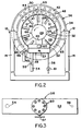
- FIGS. 1 and 2 illustrate a ducted-fan type snowmaking machine as described in detail in US-A-4,214,700 and US-A-4,105,161, the disclosures of both of which are incorporated herein by reference.
- the snowmaking machine includes an axial flow, ducted fan assembly 10 pivotally mounted by pins 12 on a yoke 14.
- the yoke 14 is rotatably mounted by a support tube 16 on a tripod or other base or carriage 18 (schematically depicted in Fig. 1) of the type shown in the aforementioned patents.
- the yoke 14 is rotatable relative to the base 18 about a vertical axis A through a 360 degree range.
- An electrical control box 20 is mounted on the base 18 and includes suitable switches and the like for operating the assembly 10 in accordance with the invention as explained below.
- the fan assembly 10 comprises an axially elongated duct or cowling 22 having a rotatable impeller 24 with a complement of circumferentially spaced, radially projecting blades 26 mounted thereon.
- the impeller 24 is driven in one direction of rotation (counterclockwise as viewed in Figure 2) by a variable speed drive motor 28 and control means (to be described in detail below), the motor being mounted coaxially in the duct 22 by a suitable support 30 fixed in the duct 22 in such position that the axis of rotation of the impeller coincides with the longitudinal axis of the duct.
- a plurality of circumferentially spaced, longitudinally and laterally curved vanes 31 are fixed on and equally distributed about the inner surface of the duct 22 and forwardly of the fan blades 26 for the purpose of converting the generally spiral air flow generated by rotation of the impeller 24 to a substantially linear, unidirectional air stream for discharge from the front or discharge end 32 of the duct 22.
- the duct 22 includes an air intake or rear end 33 covered by a screen 34 through which outside air is drawn by the impeller 24.
- Water spray means 36 and nucleating or seeding means 38 are positioned at the discharge end 32 of the duct 22 above and below the discharged air stream as is conventional, except as explained below.
- the water spray means 36 comprises arcuate water manifolds 40, 42, and 44 in communication with a supply of water via a pipe 45 and a valve 46.
- An arcuate array of adjustable water nozzles 47, 48, and 50 on the respective manifolds enables the water to be discharged in spray form into the air stream.
- the nucleating means 38 comprises a reservoir 52 having a water inlet 54 in communication with a source of water via a valve 55, and a compressed air inlet 56 in communication with a source of compressed air.
- a known mixing valve (not shown) and a valve operator 57 carried by the reservoir.
- a plurality of nucleating nozzles 60 arranged in a circle and directed upwardly and forwardly of the duct.
- the nozzles 60 are arranged to direct a mixture of water and compressed air upwardly into the air stream to facilitate formation (seeding) of snow crystals.
- the water spray components shown in Figures 1 and 2 are described in more detail in US-A-4,213,700, although the invention is not intended to be limited to those particular components.
- the nucleating means 38 differ from existing nucleating devices in two significant aspects. First, the nucleating means 38 employs a plurality of nozzles, rather than one. Second, the nucleating nozzles are mounted in such manner that they are within the confines of the duct 22 rather than external thereof. Both of these differences result in significant reductions in noise levels.
- the impeller 24 is driven by a variable speed motor 28.
- the motor may comprise an electrical or hydraulic motor whose speed is variable, typically over a selected range (such as 900-2200 rpm), to provide, for the particular size duct used, an air stream of a volume and velocity suitable for the making of acceptable quantities of snow.
- Any one of a number of commercially available, variable speed electric motors may be used and equipped with a known speed control or rheostat 62 having an adjustable knob 64.
- a known variable frequency device may be used to vary the speed of the motor.
- the speed control device is incorporated in the electrical control box 20 as shown schematically in Figure 1 for convenient access to the operator of the snowmaking apparatus.
- impeller blades 26 are spaced axially rearwardly or upstream from the vanes 31 by a distance sufficient to produce a substantial reduction in noise resulting from the rotation of the blades past the vanes. This characteristic of the invention will be explained in more detail shortly.
- the invention may be manufactured as original equipment snowmaking apparatus. However, it also may be retrofitted to existing snowmaking apparatus.
- the speed of the drive motor 28, and thus the impeller 24, is adjustable to provide a preselected noise level during the snowmaking operation that is suited to the proximity of the snowmaking apparatus to an area inhabited by people or wildlife.
- the impeller speed typically is selected at a first, relatively high level, such as 1750 rpm, when the apparatus is at a remote location from the inhabited area to produce a relatively large amount of snow over a given time period with an attendant elevated noise level of operation.
- the impeller speed may be adjusted to a lower level, such as 1200 rpm, if the apparatus is located closer to the inhabited area. Lowering of the impeller speed may result in the production of a smaller amount of snow over the same time period, but the noise level resulting from the lower impeller speed will be appreciably reduced compared to the noise level resulting from the higher impeller speed.
- Noise level control by means of the invention is illustrated in the following Table which includes data using commercially available Axipal and Joy fans of the diameters indicated and operated at two different speeds, for example 1750 rpm and 1200 rpm, representing impeller speeds that would be employed at locations remote and proximate, respectively, to an inhabited area.
- the noise level was measured in terms of logarithmic scale decibel average (dbA) wherein an increase or decrease of 3 dbA represents a doubling or halving of the apparent level of noise of the snowmaking operation.
- dbA logarithmic scale decibel average
- the front and back measurements were taken directly from in front and back of the apparatus whereas the right (RT) and left (LT) side measurements were taken at 90° to the apparatus.
- the snowmaking apparatus can be operated at the higher impeller speed at a location remote from the inhabited area to produce a greater amount of snow over a given time period at a higher noise level.
- the higher noise level will not be objectionable.
- the amount of water directed into the air stream discharged from the duct 22 may be varied in response to variations in the impeller speed to maintain proper conditions for snowmaking.
- the amount of water introduced into the air stream by the water spray means 36 and the amount of water and compressed air introduced by the nucleating means 38 may have to be correspondingly or proportionately reduced or increased, depending on such variable factors as ambient temperature and humidity.
- apparatus constructed and operated in accordance with the invention includes the valve 55 in the water supply line to the reservoir 53 and another valve 61 in the compressed air line 56.
- valves may be used in conjunction with the valve 46 to control not only the water flow rate to the manifolds 40, 42, and 44 but also to the seeding nozzles 60 in response to variations in the speed of the impeller so as to maintain proper air/water/seeding conditions for snowmaking.
- noise levels at the left side of the duct were reduced in one test from 93 dbA at 20 feet (6,1 m) to 80 dbA, and at 66 feet (20,1 m) from 81 dbA to 68 dbA. Similar decreases were measured at the right side of the duct at corresponding distances.
- noise levels referred to are those resulting from a comparison of a prior art machine in which a single nucleating nozzle is external of the duct and the same kind of machine wherein there is a plurality of such nozzles located within the confines of the duct as described herein.
- each nozzle 60 As shown in Figures 2 and 3, eight circumferentially spaced nucleating nozzles 60 are provided. However, more or less may be used if desired. Further, the array of nozzles may be encircled by a ring or collar if desired. It is preferable to concentrate the nozzles in a grouping below the longitudinal axis of the duct so as to obtain as much as possible a uniform flow of compressed air and water through each nozzle.
- Air flow straightening vanes like the vanes 31 have been used heretofore to convert the spiraling air stream produced by rotation of the fan blades to a linear, laminar flow stream. It has been the custom to locate the rear edges of the vanes quite close to the leading edges of the blades to provide what was believed to be the most efficient conversion of the flow of the air stream. It has been discovered, however, that the spacing between the rear edges of the vanes and the leading edges of the blades has a significant influence on the level of noise generated by operation of the impeller.
- the data show the noise levels at the several positions produced when the leading edges of the fan blades are spaced .25, 2.75, 4.5, and 5.0 inches (6.4, 69.9, 114.3, and 127 mm), respectively, from the rear edges of the vanes 31.
- the data shown in Figure 4 were produced by an impeller having blades like those shown in Figure 2 wherein the tip 65 of each blade has appreciably greater circumferential length than that of the root 66.
- the blades shown in Figure 2 are conventional in Axipal fans.
- conventional ducted-fan snowmaking machinery may be modified in any one or more of four different ways to control the level of noise generated by operation of such machinery.
- the speed of rotation of the impeller may be varied;
- the conventional single nucleating nozzle may be replaced by a plurality of nozzles;
- the nucleating nozzles may be located within the confines of the duct; and
- the space between the rear ends of the air stream straightening vanes and the leading edges of the impeller fan blades may be adjusted to be between about 2 and 5 inches (5,1 - 12,7 cm).
Landscapes
- Engineering & Computer Science (AREA)
- Mechanical Engineering (AREA)
- General Engineering & Computer Science (AREA)
- Physics & Mathematics (AREA)
- Thermal Sciences (AREA)
- Structures Of Non-Positive Displacement Pumps (AREA)
- Control Of Positive-Displacement Air Blowers (AREA)
Claims (15)
- Vorrichtung zur Herstellung von Schnee mit einem Rohr (22), in dem ein drehbewegliches Flügelrad (24) zur Erzeugung eines Luftstromes zur Abgabe an einem Ende des Rohres angeordnet ist, und einer Einrichtung (36) zur Abgabe einer variablen Wassermenge an den Luftstrom in einer für die Herstellung von Schnee geeigneten Menge, gekennzeichnet durch- eine Antriebseinrichtung (28) mit variabler Geschwindigkeit zum Antrieb des Flügelrades mit variablen Geschwindigkeiten, die zur Erzeugung vorbestimmter relativ hoher und niedriger Geräuschpegel gewählt werden, und- eine Einrichtung 46 zur Variierung der an den Luftstrom abgegebenen Wassermenge in Abhängigkeit von der Veränderung der Geschwindigkeit des Flügelrades.
- Vorrichtung nach Anspruch 1, weiterhin dadurch gekennzeichnet, daß die Geschwindigkeit der Antriebseinrichtung in einem solchen Maße einstellbar ist, daß der relativ hohe Geräuschpegel wenigsten sechsmal so groß ist wie der relativ niedrige Geräuschpegel.
- Vorrichtung nach Anspruch 2, weiterhin dadurch gekennzeichnet, daß die prozentuale Reduzierung zwischen dem relativ hohen und dem relativ niedrigen Geräuschpegel zwischen dem Sechs- und Zwölffachen der entsprechenden prozentualen Geschwindigkeitsreduzierung des Flügelrades liegt.
- Vorrichtung nach Anspruch 1, weiterhin dadurch gekennzeichnet, daß das Flügelrad Flügel (26) aufweist und das Rohr strömungsabseitig von den Flügeln des Flügelrades Schaufeln (31) zum Glätten des Luftstromes aufweist, wobei die Schaufeln mit einem Abstand zwischen zwei und fünf Zoll strömungsabseitig gegenüber den Flügeln angeordnet sind.
- Vorrichtung nach Anspruch 4 weiterhin dadurch gekennzeichnet, daß jede Schaufel eine Spitze (65) und eine Wurzel (66) aufweist, wobei die Spitze eine größere Umfangslänge aufweist als die Wurzel.
- Vorrichtung nach Anspruch 1, die weiterhin durch eine Düseneinrichtung (38) zur Abgabe von zerstäubter Luft und zerstäubtem Wasser an den Luftstrom gekennzeichnet ist, wobei die Düseneinrichtung innerhalb des Rohres angeordnet ist.
- Vorrichtung nach Anspruch 6, weiterhin dadurch gekennzeichnet, daß die Düseneinrichtung eine Mehrzahl von Düsen (60) enthält, die innerhalb des Rohres angeordnet sind.
- Vorrichtung nach Anspruch 7, weiterhin dadurch gekennzeichnet, daß die Düsen in Kreisform angeordnet sind.
- Vorrichtung nach Anspruch 6, weiterhin dadurch gekennzeichnet, daß die Düseneinrichtung von einer kreisförmigen Wand umgeben ist.
- Verfahren zur Herstellung von Schnee, bei dem ein Flügelrad (24) innerhalb eines Rohres (22) gedreht wird, um einen Luftstrom zur Abgabe an einem Ende des Rohres zu erzeugen, und bei dem eine variable Wassermenge an den Luftstrom in einer solchen Menge abgegeben wird, daß Schnee entsteht, dadurch gekennzeichnet, daß die Drehgeschwindigkeit des Flügelrades variiert wird, um relativ höhere und relativ niedrigere vorbestimmte Geräuschpegel zu erzeugen; und daß die an den Luftstrom abgegebene Wassermenge in Abhängigkeit von der Veränderung der Drehgeschwindigkeit des Flügelrades variiert wird.
- Verfahren nach Anspruch 10, weiterhin dadurch gekennzeichnet, daß die Drehgeschwindigkeit des Flügelrades in einem solchen Maße variiert wird, daß eine prozentuale Veränderung zwischen den relativ hohen und niedrigen Geräuschpegeln erzeugt wird, die wenigstens sechsmal so groß ist wie die entsprechende prozentuale Veränderung in der Drehgeschwindigkeit des Flügelrades.
- Verfahren nach Anspruch 10, weiterhin dadurch gekennzeichnet, daß eine zerstäubte Mischung von Wasser und Luft an den Luftstrom abgegeben wird.
- Verfahren nach Anspruch 12, weiterhin dadurch gekennzeichnet, daß die zerstäubte Mischung aus einer Position innerhalb des Rohres an den Luftstrom abgegeben wird.
- Verfahren nach Anspruch 13, weiterhin dadurch gekennzeichnet, daß die zerstäubte Mischung über eine Mehrzahl von Düsen in den Luftstrom gesprüht wird.
- Verfahren nach Anspruch 14, weiterhin dadurch gekennzeichnet, daß die Mehrzahl von Düsen von einem Ring umgeben wird.
Applications Claiming Priority (2)
| Application Number | Priority Date | Filing Date | Title |
|---|---|---|---|
| US07/639,981 US5167367A (en) | 1991-01-11 | 1991-01-11 | Snowmaking apparatus and methods |
| US639981 | 1991-01-11 |
Publications (2)
| Publication Number | Publication Date |
|---|---|
| EP0494380A1 EP0494380A1 (de) | 1992-07-15 |
| EP0494380B1 true EP0494380B1 (de) | 1995-03-15 |
Family
ID=24566354
Family Applications (1)
| Application Number | Title | Priority Date | Filing Date |
|---|---|---|---|
| EP91121067A Expired - Lifetime EP0494380B1 (de) | 1991-01-11 | 1991-12-09 | Verfahren und Vorrichtung zur Herstellung von Schnee |
Country Status (5)
| Country | Link |
|---|---|
| US (1) | US5167367A (de) |
| EP (1) | EP0494380B1 (de) |
| JP (1) | JPH04295575A (de) |
| AT (1) | ATE119975T1 (de) |
| CA (1) | CA2057958A1 (de) |
Cited By (1)
| Publication number | Priority date | Publication date | Assignee | Title |
|---|---|---|---|---|
| US11813548B2 (en) | 2018-04-12 | 2023-11-14 | Resource West, Inc. | Evaporator for ambient water bodies, and related system and method |
Families Citing this family (15)
| Publication number | Priority date | Publication date | Assignee | Title |
|---|---|---|---|---|
| US5400966A (en) * | 1993-08-05 | 1995-03-28 | Holimont, Inc. | Machine for making artificial snow and method |
| US5379937A (en) * | 1994-01-18 | 1995-01-10 | Rothe Welding And Fabrication, Inc. | Nucleator assembly for snowmaking apparatus |
| CA2116368A1 (en) * | 1994-02-24 | 1995-08-25 | Louis Handfield | Snowmaking gun |
| US5836513A (en) * | 1996-03-20 | 1998-11-17 | Lake Effect Technologies, Inc. | Apparatus for and method of making snow |
| US6129290A (en) * | 1997-11-06 | 2000-10-10 | Nikkanen; John P. | Snow maker |
| US6032204A (en) * | 1998-03-09 | 2000-02-29 | Advanced Micro Devices, Inc. | Microcontroller with a synchronous serial interface and a two-channel DMA unit configured together for providing DMA requests to the first and second DMA channel |
| US7290722B1 (en) | 2003-12-16 | 2007-11-06 | Snow Machines, Inc. | Method and apparatus for making snow |
| AT10713U1 (de) * | 2008-09-26 | 2009-08-15 | Iag Ind Automatisierungsgesell | Schneekanone mit einem lüfterrohr |
| WO2011119229A1 (en) | 2010-03-24 | 2011-09-29 | C.W. Machine Worx, Ltd. | Dust suppression apparatus |
| US8282214B2 (en) * | 2010-05-19 | 2012-10-09 | Disney Enterprises, Inc. | Display system using projection screens formed of flowing snow |
| US9890057B2 (en) | 2013-10-24 | 2018-02-13 | Kelly K. Houston | System and method for on site aerial dissemination and atmospheric disposal of all leachates and wastewaters |
| US10478875B2 (en) * | 2013-10-24 | 2019-11-19 | Aerosolization Equity Investments, Llc | System and method for applying covering material with an aerosolization system |
| CA163646S (en) * | 2015-04-14 | 2016-03-15 | Bucceri Alfio | Snow making machine |
| US10337782B2 (en) * | 2016-05-18 | 2019-07-02 | Snow Realm Holdings, LLC | Lightweight, portable, external nucleation fan gun |
| USD987199S1 (en) * | 2020-11-17 | 2023-05-23 | Demaclenko It S.R.L. | Fire extinguishing autogun |
Family Cites Families (12)
| Publication number | Priority date | Publication date | Assignee | Title |
|---|---|---|---|---|
| AT283398B (de) * | 1968-04-08 | 1970-08-10 | Linde Ag | Verfahren und Vorrichtung zur Erzeugung von künstlichem Schnee |
| US4004732A (en) * | 1974-08-16 | 1977-01-25 | Hanson Alden W | Snow making method |
| US4083492A (en) * | 1976-10-08 | 1978-04-11 | Dewey Gordon C | Apparatus and method for preventing icing on a snow-making machine |
| US4105161A (en) * | 1976-11-18 | 1978-08-08 | Boyne Mountain Lodge, Inc. | Method of making artificial snow |
| JPS5375510A (en) * | 1976-12-15 | 1978-07-05 | Agency Of Ind Science & Technol | Noise control method for axial blowers |
| US4214700A (en) * | 1978-10-27 | 1980-07-29 | Snow Machines, Inc. | Method and apparatus for making snow for ski slopes and the like |
| US4222519A (en) * | 1979-09-17 | 1980-09-16 | Boyne Mountain Lodge, Inc. | Method and machine for making artificial snow |
| US4597524A (en) * | 1982-03-22 | 1986-07-01 | Albertsson Stig L | Snow making machine |
| US4493457A (en) * | 1983-04-18 | 1985-01-15 | Nubs Nob, Inc. | Method and apparatus for making artificial snow |
| FR2579732B1 (fr) * | 1985-03-27 | 1987-09-25 | Ene Ste Civile | Dispositifs et procedes de fabrication de neige artificielle |
| US4682729A (en) * | 1985-06-03 | 1987-07-28 | The Dewey Electronics Corporation | Snowmaking machine with compressed air driven reaction fan |
| US4813598A (en) * | 1987-07-17 | 1989-03-21 | Mt. Holly, Inc. | Snow making apparatus and method for making snow |
-
1991
- 1991-01-11 US US07/639,981 patent/US5167367A/en not_active Expired - Fee Related
- 1991-12-09 AT AT91121067T patent/ATE119975T1/de active
- 1991-12-09 EP EP91121067A patent/EP0494380B1/de not_active Expired - Lifetime
- 1991-12-18 CA CA002057958A patent/CA2057958A1/en not_active Abandoned
-
1992
- 1992-01-10 JP JP4002999A patent/JPH04295575A/ja active Pending
Cited By (1)
| Publication number | Priority date | Publication date | Assignee | Title |
|---|---|---|---|---|
| US11813548B2 (en) | 2018-04-12 | 2023-11-14 | Resource West, Inc. | Evaporator for ambient water bodies, and related system and method |
Also Published As
| Publication number | Publication date |
|---|---|
| JPH04295575A (ja) | 1992-10-20 |
| EP0494380A1 (de) | 1992-07-15 |
| ATE119975T1 (de) | 1995-04-15 |
| US5167367A (en) | 1992-12-01 |
| CA2057958A1 (en) | 1992-07-12 |
Similar Documents
| Publication | Publication Date | Title |
|---|---|---|
| EP0494380A1 (de) | Verfahren und Vorrichtung zur Herstellung von Schnee | |
| US20040120815A1 (en) | Cooling fan | |
| US4657483A (en) | Shrouded household fan | |
| CN103104514B (zh) | 一种无叶风扇 | |
| US5101847A (en) | Method and apparatus for equalizing airflow velocity | |
| CN104389768B (zh) | 内进风式无叶风扇 | |
| JPS5830329A (ja) | 表面通気用羽根車 | |
| SE443842B (sv) | Axialflekt med ett speciellt utforande av utloppskammaren | |
| CN105484980A (zh) | 风扇 | |
| EP0204573A1 (de) | Rasenmäher | |
| JP3429263B2 (ja) | 加湿装置 | |
| US4222519A (en) | Method and machine for making artificial snow | |
| US5147653A (en) | Directed fiber preforming | |
| CN208798581U (zh) | 一种自适应仿形果园喷雾机 | |
| US4657712A (en) | Humidifier | |
| CN1104600C (zh) | 用于控制空调器中排放空气流量的装置及其方法 | |
| CN1117954C (zh) | 一种模拟自然风的空调末端装置 | |
| US20030177603A1 (en) | Portable blower | |
| US20040056110A1 (en) | Illusionary snow apparatus with reduced noise | |
| CN209147349U (zh) | 一种组合式空调机组的风机段及空调机组 | |
| EP0023784B1 (de) | Motorgetriebenes Zentrifugalgebläse für Luft | |
| RU2206362C1 (ru) | Устройство для формирования облака или завесы из дисперсных легких элементов | |
| CN218194627U (zh) | 一种摆动喷砂装置 | |
| JPS6443118A (en) | Mowed grass discharging apparatus of mower | |
| CN223769151U (zh) | 一种速食熟化后冷却装置 |
Legal Events
| Date | Code | Title | Description |
|---|---|---|---|
| PUAI | Public reference made under article 153(3) epc to a published international application that has entered the european phase |
Free format text: ORIGINAL CODE: 0009012 |
|
| AK | Designated contracting states |
Kind code of ref document: A1 Designated state(s): AT CH FR IT LI SE |
|
| 17P | Request for examination filed |
Effective date: 19920724 |
|
| TCAT | At: translation of patent claims filed | ||
| 17Q | First examination report despatched |
Effective date: 19930504 |
|
| RIN1 | Information on inventor provided before grant (corrected) |
Inventor name: VANDERKELEN, JOSEPH M. Inventor name: KOENIG, DONALD R. Inventor name: TOPHAM, WILLIAM C. Inventor name: VANDERKELEN, JAMES B. |
|
| GRAA | (expected) grant |
Free format text: ORIGINAL CODE: 0009210 |
|
| ITF | It: translation for a ep patent filed | ||
| AK | Designated contracting states |
Kind code of ref document: B1 Designated state(s): AT CH FR IT LI SE |
|
| REF | Corresponds to: |
Ref document number: 119975 Country of ref document: AT Date of ref document: 19950415 Kind code of ref document: T |
|
| ET | Fr: translation filed | ||
| PGFP | Annual fee paid to national office [announced via postgrant information from national office to epo] |
Ref country code: FR Payment date: 19951024 Year of fee payment: 5 |
|
| PG25 | Lapsed in a contracting state [announced via postgrant information from national office to epo] |
Ref country code: SE Effective date: 19951210 |
|
| PGFP | Annual fee paid to national office [announced via postgrant information from national office to epo] |
Ref country code: AT Payment date: 19951219 Year of fee payment: 5 |
|
| PGFP | Annual fee paid to national office [announced via postgrant information from national office to epo] |
Ref country code: CH Payment date: 19951229 Year of fee payment: 5 |
|
| PLBE | No opposition filed within time limit |
Free format text: ORIGINAL CODE: 0009261 |
|
| STAA | Information on the status of an ep patent application or granted ep patent |
Free format text: STATUS: NO OPPOSITION FILED WITHIN TIME LIMIT |
|
| 26N | No opposition filed | ||
| PG25 | Lapsed in a contracting state [announced via postgrant information from national office to epo] |
Ref country code: AT Effective date: 19961209 |
|
| PG25 | Lapsed in a contracting state [announced via postgrant information from national office to epo] |
Ref country code: LI Effective date: 19961231 Ref country code: CH Effective date: 19961231 |
|
| REG | Reference to a national code |
Ref country code: CH Ref legal event code: PL |
|
| PG25 | Lapsed in a contracting state [announced via postgrant information from national office to epo] |
Ref country code: FR Effective date: 19970829 |
|
| REG | Reference to a national code |
Ref country code: FR Ref legal event code: ST |
|
| PG25 | Lapsed in a contracting state [announced via postgrant information from national office to epo] |
Ref country code: IT Free format text: LAPSE BECAUSE OF NON-PAYMENT OF DUE FEES;WARNING: LAPSES OF ITALIAN PATENTS WITH EFFECTIVE DATE BEFORE 2007 MAY HAVE OCCURRED AT ANY TIME BEFORE 2007. THE CORRECT EFFECTIVE DATE MAY BE DIFFERENT FROM THE ONE RECORDED. Effective date: 20051209 |