EP0494531A2 - Dispositif de soupape - Google Patents
Dispositif de soupape Download PDFInfo
- Publication number
- EP0494531A2 EP0494531A2 EP19910311862 EP91311862A EP0494531A2 EP 0494531 A2 EP0494531 A2 EP 0494531A2 EP 19910311862 EP19910311862 EP 19910311862 EP 91311862 A EP91311862 A EP 91311862A EP 0494531 A2 EP0494531 A2 EP 0494531A2
- Authority
- EP
- European Patent Office
- Prior art keywords
- recess
- outlet duct
- fluid
- groove
- substrate
- Prior art date
- Legal status (The legal status is an assumption and is not a legal conclusion. Google has not performed a legal analysis and makes no representation as to the accuracy of the status listed.)
- Ceased
Links
- 239000012530 fluid Substances 0.000 claims abstract description 26
- 239000000758 substrate Substances 0.000 claims abstract description 26
- 230000015572 biosynthetic process Effects 0.000 claims abstract description 3
- 229910052710 silicon Inorganic materials 0.000 claims abstract description 3
- 239000010703 silicon Substances 0.000 claims abstract description 3
- 238000000034 method Methods 0.000 claims abstract 2
- 238000005459 micromachining Methods 0.000 claims abstract 2
- 238000002347 injection Methods 0.000 description 2
- 239000007924 injection Substances 0.000 description 2
- 230000000717 retained effect Effects 0.000 description 1
Images
Classifications
-
- F—MECHANICAL ENGINEERING; LIGHTING; HEATING; WEAPONS; BLASTING
- F15—FLUID-PRESSURE ACTUATORS; HYDRAULICS OR PNEUMATICS IN GENERAL
- F15C—FLUID-CIRCUIT ELEMENTS PREDOMINANTLY USED FOR COMPUTING OR CONTROL PURPOSES
- F15C1/00—Circuit elements having no moving parts
- F15C1/16—Vortex devices, i.e. devices in which use is made of the pressure drop associated with vortex motion in a fluid
-
- Y—GENERAL TAGGING OF NEW TECHNOLOGICAL DEVELOPMENTS; GENERAL TAGGING OF CROSS-SECTIONAL TECHNOLOGIES SPANNING OVER SEVERAL SECTIONS OF THE IPC; TECHNICAL SUBJECTS COVERED BY FORMER USPC CROSS-REFERENCE ART COLLECTIONS [XRACs] AND DIGESTS
- Y10—TECHNICAL SUBJECTS COVERED BY FORMER USPC
- Y10T—TECHNICAL SUBJECTS COVERED BY FORMER US CLASSIFICATION
- Y10T137/00—Fluid handling
- Y10T137/206—Flow affected by fluid contact, energy field or coanda effect [e.g., pure fluid device or system]
- Y10T137/2087—Means to cause rotational flow of fluid [e.g., vortex generator]
- Y10T137/2109—By tangential input to axial output [e.g., vortex amplifier]
- Y10T137/2115—With means to vary input or output of device
-
- Y—GENERAL TAGGING OF NEW TECHNOLOGICAL DEVELOPMENTS; GENERAL TAGGING OF CROSS-SECTIONAL TECHNOLOGIES SPANNING OVER SEVERAL SECTIONS OF THE IPC; TECHNICAL SUBJECTS COVERED BY FORMER USPC CROSS-REFERENCE ART COLLECTIONS [XRACs] AND DIGESTS
- Y10—TECHNICAL SUBJECTS COVERED BY FORMER USPC
- Y10T—TECHNICAL SUBJECTS COVERED BY FORMER US CLASSIFICATION
- Y10T137/00—Fluid handling
- Y10T137/206—Flow affected by fluid contact, energy field or coanda effect [e.g., pure fluid device or system]
- Y10T137/2224—Structure of body of device
Definitions
- This invention relates to valve devices, and particularly to miniature non-return valves.
- a non-return valve comprising a circular recess; an inlet substantially coaxially aligned with the recess; an annular groove substantially coaxially aligned with the recess and communicating with the recess at a plurality of points within the groove; and an outlet duct communicating with the groove, whereby fluid entering the inlet passes through the recess, the annular groove and the outlet duct substantially unimpeded, whereas fluid entering the outlet duct is caused to form into a vortex in said recess, and flow of that fluid to the inlet is thereby substantially inhibited.
- the recess is provided in a first substrate and the annular groove and the outlet duct are provided in a second substrate attached to said first substrate.
- a first substrate 1 has a central aperture 3 therethrough.
- Figure 2 shows a second substrate 5 having a circular recess 7 formed in its upper surface. Eight apertures 9 extend downwardly from the recess 7 at equal angular spacings.
- a control groove 11 extends tangentially from the recess 7 to a control inlet 13.
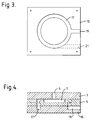
- a third substrate 15 ( Figure 3) has an annular groove 17 therein, of outside diameter similar to that of the recess 7.
- An outlet duct 19 extends radially from the groove 17 to the edge of the substrate.
- the substrates may be formed of silicon.
- Figure 4 shows a schematic cross-sectional view of the assembled device.
- fluid entering the aperture 3 will pass into the recess 7, through the apertures 9, into the groove 17, and out of the outlet duct 19, with little impedance. If fluid is caused to enter the outlet duct 19, on the other hand, it will divide on entry to the groove 17. Some of the fluid will pass in one direction round the groove and the rest in the opposite direction. The fluid will pass through the apertures 9 and into the recess 7. If control fluid is injected into the control duct 11 via the inlet 13 it will cause the fluid in the recess 7 to rotate clockwise as viewed in Figure 2. A vortex will therefore be produced in the recess, and the fluid will not pass out of the aperture 3. The fluid flow through the valve is therefore unidirectional.
- the outlet duct is positioned to be tangential to the groove 17, as shown by a dotted line at 21 in Figure 3. Fluid entering via the aperture 3 passes through the valve to the outlet duct 21 substantially unimpeded, as before. If fluid is caused to enter the outlet duct 21, it will rotate round the groove 17 in a clockwise direction (as viewed in Figure 3), pass up through the apertures 9 and enter the recess 7. It will still have a tendency to rotate clockwise, and a vortex will be set up in the recess 7, even without the injection of fluid into the control duct 13. That duct could, therefore, be omitted from the device. However, the control duct could alternatively be retained, and the injection of fluid into that duct would then increase the clockwise flow of the fluid and thereby enhance the formation of the vortex.
- the dimensions of the substrates and of the cavities and apertures formed therein may be, for example, as follows:
- a pair of valves in accordance with the invention may be used in, for example, a microminiature pump, and other components of the pump may be formed on the same substrates as the valve components.
Landscapes
- Engineering & Computer Science (AREA)
- General Engineering & Computer Science (AREA)
- Theoretical Computer Science (AREA)
- Physics & Mathematics (AREA)
- Fluid Mechanics (AREA)
- Mechanical Engineering (AREA)
- Lift Valve (AREA)
Applications Claiming Priority (2)
| Application Number | Priority Date | Filing Date | Title |
|---|---|---|---|
| GB9100679 | 1991-01-11 | ||
| GB9100679A GB2251703B (en) | 1991-01-11 | 1991-01-11 | Valve devices |
Publications (2)
| Publication Number | Publication Date |
|---|---|
| EP0494531A2 true EP0494531A2 (fr) | 1992-07-15 |
| EP0494531A3 EP0494531A3 (en) | 1992-09-23 |
Family
ID=10688341
Family Applications (1)
| Application Number | Title | Priority Date | Filing Date |
|---|---|---|---|
| EP19910311862 Ceased EP0494531A3 (en) | 1991-01-11 | 1991-12-20 | Valve devices |
Country Status (4)
| Country | Link |
|---|---|
| US (1) | US5197517A (fr) |
| EP (1) | EP0494531A3 (fr) |
| JP (1) | JPH04321805A (fr) |
| GB (1) | GB2251703B (fr) |
Cited By (1)
| Publication number | Priority date | Publication date | Assignee | Title |
|---|---|---|---|---|
| EP0844478A1 (fr) * | 1996-11-25 | 1998-05-27 | Vermes Mikrotechnik GmbH | Dispositif pour l'analyse automatique et continue des échantillons liquides |
Families Citing this family (40)
| Publication number | Priority date | Publication date | Assignee | Title |
|---|---|---|---|---|
| US5655961A (en) * | 1994-10-12 | 1997-08-12 | Acres Gaming, Inc. | Method for operating networked gaming devices |
| US6227809B1 (en) | 1995-03-09 | 2001-05-08 | University Of Washington | Method for making micropumps |
| US5876187A (en) * | 1995-03-09 | 1999-03-02 | University Of Washington | Micropumps with fixed valves |
| US6033544A (en) * | 1996-10-11 | 2000-03-07 | Sarnoff Corporation | Liquid distribution system |
| US6533366B1 (en) | 1996-05-29 | 2003-03-18 | Kelsey-Hayes Company | Vehicle hydraulic braking systems incorporating micro-machined technology |
| US6393685B1 (en) | 1997-06-10 | 2002-05-28 | The Regents Of The University Of California | Microjoinery methods and devices |
| US6117396A (en) * | 1998-02-18 | 2000-09-12 | Orchid Biocomputer, Inc. | Device for delivering defined volumes |
| WO2000014415A2 (fr) | 1998-09-03 | 2000-03-16 | Lucas Novasensor | Dispositif micromecanique proportionnel |
| US6523560B1 (en) | 1998-09-03 | 2003-02-25 | General Electric Corporation | Microvalve with pressure equalization |
| US7011378B2 (en) * | 1998-09-03 | 2006-03-14 | Ge Novasensor, Inc. | Proportional micromechanical valve |
| US6540203B1 (en) | 1999-03-22 | 2003-04-01 | Kelsey-Hayes Company | Pilot operated microvalve device |
| US6845962B1 (en) * | 2000-03-22 | 2005-01-25 | Kelsey-Hayes Company | Thermally actuated microvalve device |
| US6694998B1 (en) | 2000-03-22 | 2004-02-24 | Kelsey-Hayes Company | Micromachined structure usable in pressure regulating microvalve and proportional microvalve |
| US6494804B1 (en) | 2000-06-20 | 2002-12-17 | Kelsey-Hayes Company | Microvalve for electronically controlled transmission |
| US6581640B1 (en) | 2000-08-16 | 2003-06-24 | Kelsey-Hayes Company | Laminated manifold for microvalve |
| AU2002950802A0 (en) * | 2002-08-15 | 2002-09-12 | Skala, Peter | Fluidic vortex amplifier |
| US20070251586A1 (en) * | 2003-11-24 | 2007-11-01 | Fuller Edward N | Electro-pneumatic control valve with microvalve pilot |
| US8011388B2 (en) * | 2003-11-24 | 2011-09-06 | Microstaq, INC | Thermally actuated microvalve with multiple fluid ports |
| EP1694990A4 (fr) * | 2003-11-24 | 2009-12-09 | Microstaq Inc | Dispositif de micro-vanne permettant de controler un compresseur a deplacement variable |
| KR20070012375A (ko) * | 2004-02-27 | 2007-01-25 | 알루미나 마이크로 엘엘씨 | 하이브리드 마이크로/매크로 평판 밸브 |
| JP5196422B2 (ja) * | 2004-03-05 | 2013-05-15 | ドゥンアン、マイクロスタック、インク | マイクロバルブ形成のための選択的ボンディング |
| US7217428B2 (en) * | 2004-05-28 | 2007-05-15 | Technology Innovations Llc | Drug delivery apparatus utilizing cantilever |
| US7156365B2 (en) * | 2004-07-27 | 2007-01-02 | Kelsey-Hayes Company | Method of controlling microvalve actuator |
| EP1836399A1 (fr) * | 2005-01-14 | 2007-09-26 | Alumina Micro LLC | Systeme et procede de commande d'un compresseur a debit variable |
| FR2885820B1 (fr) * | 2005-05-18 | 2007-06-22 | Rexam Dispensing Systems Sas | Buse a chambre tourbillonnaire |
| US8156962B2 (en) * | 2006-12-15 | 2012-04-17 | Dunan Microstaq, Inc. | Microvalve device |
| CN101675280B (zh) | 2007-03-30 | 2013-05-15 | 盾安美斯泰克公司(美国) | 先导式微型滑阀 |
| WO2008121365A1 (fr) | 2007-03-31 | 2008-10-09 | Microstaq, Inc. | Distributeur à tiroir commandé par pilote |
| JP2011530683A (ja) * | 2008-08-09 | 2011-12-22 | マイクラスタック、インク | 改良型のマイクロバルブ・デバイス |
| US8113482B2 (en) | 2008-08-12 | 2012-02-14 | DunAn Microstaq | Microvalve device with improved fluid routing |
| CN102308131B (zh) | 2008-12-06 | 2014-01-08 | 盾安美斯泰克有限公司 | 流体流动控制组件 |
| NL2002580C2 (en) | 2009-02-27 | 2010-08-30 | Meijn Food Proc Technology B V | Deskinner for poultry parts. |
| WO2010117874A2 (fr) | 2009-04-05 | 2010-10-14 | Microstaq, Inc. | Procédé et structure pour optimiser la performance d'un échangeur de chaleur |
| US20120145252A1 (en) | 2009-08-17 | 2012-06-14 | Dunan Microstaq, Inc. | Micromachined Device and Control Method |
| US8956884B2 (en) | 2010-01-28 | 2015-02-17 | Dunan Microstaq, Inc. | Process for reconditioning semiconductor surface to facilitate bonding |
| WO2011094300A2 (fr) | 2010-01-28 | 2011-08-04 | Microstaq, Inc. | Procédé et structure de liaison par fusion sélective haute température |
| US8996141B1 (en) | 2010-08-26 | 2015-03-31 | Dunan Microstaq, Inc. | Adaptive predictive functional controller |
| US8925793B2 (en) | 2012-01-05 | 2015-01-06 | Dunan Microstaq, Inc. | Method for making a solder joint |
| US9140613B2 (en) | 2012-03-16 | 2015-09-22 | Zhejiang Dunan Hetian Metal Co., Ltd. | Superheat sensor |
| US9188375B2 (en) | 2013-12-04 | 2015-11-17 | Zhejiang Dunan Hetian Metal Co., Ltd. | Control element and check valve assembly |
Family Cites Families (13)
| Publication number | Priority date | Publication date | Assignee | Title |
|---|---|---|---|---|
| DE507713C (de) * | 1928-06-12 | 1930-09-19 | Dieter Thoma Dr Ing | Vorrichtung zur Behinderung des Rueckstroemens |
| US3324891A (en) * | 1961-04-18 | 1967-06-13 | Gen Electric | Flow regulator |
| US3515158A (en) * | 1967-11-24 | 1970-06-02 | Us Navy | Pure fluidic flow regulating system |
| FR96370E (fr) * | 1968-02-15 | 1972-06-16 | Bendix Corp | Amplificateur a fluide tourbillonnaire perfectionné. |
| US3507116A (en) * | 1968-05-29 | 1970-04-21 | Us Navy | Flueric variable thrust injector |
| US3528445A (en) * | 1969-01-02 | 1970-09-15 | Gen Electric | Laminated filter for fluid amplifiers |
| GB1256903A (fr) * | 1969-02-24 | 1971-12-15 | ||
| US3712321A (en) * | 1971-05-03 | 1973-01-23 | Philco Ford Corp | Low loss vortex fluid amplifier valve |
| GB1455418A (en) * | 1973-04-04 | 1976-11-10 | Atomic Energy Authority Uk | Fluidic devices |
| GB1575394A (en) * | 1978-05-11 | 1980-09-24 | Roberts P | Vortex diode |
| GB2020850B (en) * | 1978-05-11 | 1982-09-02 | Atomic Energy Authority Uk | Vortex diode |
| GB8521164D0 (en) * | 1985-08-23 | 1985-10-02 | British Nuclear Fuels Plc | Fluidic devices |
| US4846224A (en) * | 1988-08-04 | 1989-07-11 | California Institute Of Technology | Vortex generator for flow control |
-
1991
- 1991-01-11 GB GB9100679A patent/GB2251703B/en not_active Expired - Fee Related
- 1991-12-20 EP EP19910311862 patent/EP0494531A3/en not_active Ceased
-
1992
- 1992-01-07 JP JP4018597A patent/JPH04321805A/ja active Pending
- 1992-01-13 US US07/819,851 patent/US5197517A/en not_active Expired - Fee Related
Cited By (2)
| Publication number | Priority date | Publication date | Assignee | Title |
|---|---|---|---|---|
| EP0844478A1 (fr) * | 1996-11-25 | 1998-05-27 | Vermes Mikrotechnik GmbH | Dispositif pour l'analyse automatique et continue des échantillons liquides |
| US6458325B1 (en) | 1996-11-25 | 2002-10-01 | Abb Limited | Apparatus for analyzing liquid samples automatically and continually |
Also Published As
| Publication number | Publication date |
|---|---|
| GB9100679D0 (en) | 1991-02-27 |
| EP0494531A3 (en) | 1992-09-23 |
| JPH04321805A (ja) | 1992-11-11 |
| US5197517A (en) | 1993-03-30 |
| GB2251703B (en) | 1994-08-03 |
| GB2251703A (en) | 1992-07-15 |
Similar Documents
| Publication | Publication Date | Title |
|---|---|---|
| EP0494531A2 (fr) | Dispositif de soupape | |
| US4389159A (en) | Centrifugal pump | |
| CA1224084A (fr) | Pompe centrifuge | |
| US4267045A (en) | Labyrinth disk stack having disks with integral filter screens | |
| US4441999A (en) | Strainer means for pulp purification | |
| US4410430A (en) | Stacked-disc structure for fluid filter or valve silencer | |
| USD1024136S1 (en) | Cover for a centrifugal pump | |
| AU630566B2 (en) | Gas sparged centrifugal device | |
| DE69105703T2 (de) | Mundstückummantelung für Axiallüfter. | |
| AU2001281571B2 (en) | Hydraulic valve | |
| US11060635B2 (en) | Additively manufactured control valve flow element | |
| WO2003083336A1 (fr) | Dispositif de reduction des bruits pour systemes d'ecoulement fluidique | |
| CA2377601A1 (fr) | Elements empiles de melangeur statique | |
| EP0186891A1 (fr) | Ventilateur électrique | |
| CA1271105A (fr) | Clapet de detente ou antiretour | |
| CN101553677B (zh) | 减压阀的阀芯及其制造方法 | |
| US3794056A (en) | Fluidic pulse and flow divider | |
| ATE271153T1 (de) | Siebvorrichtung mit zwei sieben | |
| US4936546A (en) | Flow-setting valve | |
| US4830053A (en) | Fluidic devices | |
| WO1988009438A1 (fr) | Pompe centrifuge | |
| SE435783B (sv) | Plugg for hopsettning av leksakselement | |
| US5213469A (en) | Sewage pump with improved inlet construction | |
| EP3596341A1 (fr) | Ventilateur | |
| EP0373004A3 (fr) | Cadre pour accomoder et aligner des plaquettes |
Legal Events
| Date | Code | Title | Description |
|---|---|---|---|
| PUAI | Public reference made under article 153(3) epc to a published international application that has entered the european phase |
Free format text: ORIGINAL CODE: 0009012 |
|
| AK | Designated contracting states |
Kind code of ref document: A2 Designated state(s): CH DE ES FR IT LI NL |
|
| PUAL | Search report despatched |
Free format text: ORIGINAL CODE: 0009013 |
|
| AK | Designated contracting states |
Kind code of ref document: A3 Designated state(s): CH DE ES FR IT LI NL |
|
| RIN1 | Information on inventor provided before grant (corrected) |
Inventor name: PERERA, GURUGE ELMO LAKSHMAN |
|
| 17P | Request for examination filed |
Effective date: 19930114 |
|
| 17Q | First examination report despatched |
Effective date: 19940428 |
|
| STAA | Information on the status of an ep patent application or granted ep patent |
Free format text: STATUS: THE APPLICATION HAS BEEN REFUSED |
|
| 18R | Application refused |
Effective date: 19960413 |