EP0494709A2 - Système de transmission des signaux - Google Patents
Système de transmission des signaux Download PDFInfo
- Publication number
- EP0494709A2 EP0494709A2 EP92200003A EP92200003A EP0494709A2 EP 0494709 A2 EP0494709 A2 EP 0494709A2 EP 92200003 A EP92200003 A EP 92200003A EP 92200003 A EP92200003 A EP 92200003A EP 0494709 A2 EP0494709 A2 EP 0494709A2
- Authority
- EP
- European Patent Office
- Prior art keywords
- probability
- parameter
- coding
- tree
- encoded
- Prior art date
- Legal status (The legal status is an assumption and is not a legal conclusion. Google has not performed a legal analysis and makes no representation as to the accuracy of the status listed.)
- Granted
Links
- 230000008054 signal transmission Effects 0.000 title claims description 8
- 238000000034 method Methods 0.000 description 21
- 230000006870 function Effects 0.000 description 12
- 238000010586 diagram Methods 0.000 description 9
- 230000008569 process Effects 0.000 description 9
- 230000005540 biological transmission Effects 0.000 description 8
- 230000000694 effects Effects 0.000 description 5
- 230000006399 behavior Effects 0.000 description 3
- 239000002131 composite material Substances 0.000 description 3
- 230000003044 adaptive effect Effects 0.000 description 2
- 230000008901 benefit Effects 0.000 description 2
- 230000008859 change Effects 0.000 description 2
- 230000007774 longterm Effects 0.000 description 2
- 238000012986 modification Methods 0.000 description 2
- 230000004048 modification Effects 0.000 description 2
- 101001138022 Homo sapiens La-related protein 1 Proteins 0.000 description 1
- 102100020859 La-related protein 1 Human genes 0.000 description 1
- 230000004075 alteration Effects 0.000 description 1
- 238000013459 approach Methods 0.000 description 1
- 238000006243 chemical reaction Methods 0.000 description 1
- 238000010276 construction Methods 0.000 description 1
- 238000012937 correction Methods 0.000 description 1
- 230000003247 decreasing effect Effects 0.000 description 1
- 230000001419 dependent effect Effects 0.000 description 1
- 238000013461 design Methods 0.000 description 1
- 238000004519 manufacturing process Methods 0.000 description 1
- 239000013307 optical fiber Substances 0.000 description 1
- 230000010363 phase shift Effects 0.000 description 1
- 238000012545 processing Methods 0.000 description 1
- 230000009467 reduction Effects 0.000 description 1
- 230000004044 response Effects 0.000 description 1
- 238000000926 separation method Methods 0.000 description 1
- 230000003595 spectral effect Effects 0.000 description 1
Images



Classifications
-
- H—ELECTRICITY
- H03—ELECTRONIC CIRCUITRY
- H03M—CODING; DECODING; CODE CONVERSION IN GENERAL
- H03M13/00—Coding, decoding or code conversion, for error detection or error correction; Coding theory basic assumptions; Coding bounds; Error probability evaluation methods; Channel models; Simulation or testing of codes
- H03M13/25—Error detection or forward error correction by signal space coding, i.e. adding redundancy in the signal constellation, e.g. Trellis Coded Modulation [TCM]
- H03M13/256—Error detection or forward error correction by signal space coding, i.e. adding redundancy in the signal constellation, e.g. Trellis Coded Modulation [TCM] with trellis coding, e.g. with convolutional codes and TCM
-
- H—ELECTRICITY
- H03—ELECTRONIC CIRCUITRY
- H03M—CODING; DECODING; CODE CONVERSION IN GENERAL
- H03M13/00—Coding, decoding or code conversion, for error detection or error correction; Coding theory basic assumptions; Coding bounds; Error probability evaluation methods; Channel models; Simulation or testing of codes
- H03M13/03—Error detection or forward error correction by redundancy in data representation, i.e. code words containing more digits than the source words
- H03M13/23—Error detection or forward error correction by redundancy in data representation, i.e. code words containing more digits than the source words using convolutional codes, e.g. unit memory codes
-
- H—ELECTRICITY
- H03—ELECTRONIC CIRCUITRY
- H03M—CODING; DECODING; CODE CONVERSION IN GENERAL
- H03M13/00—Coding, decoding or code conversion, for error detection or error correction; Coding theory basic assumptions; Coding bounds; Error probability evaluation methods; Channel models; Simulation or testing of codes
- H03M13/25—Error detection or forward error correction by signal space coding, i.e. adding redundancy in the signal constellation, e.g. Trellis Coded Modulation [TCM]
-
- H—ELECTRICITY
- H03—ELECTRONIC CIRCUITRY
- H03M—CODING; DECODING; CODE CONVERSION IN GENERAL
- H03M13/00—Coding, decoding or code conversion, for error detection or error correction; Coding theory basic assumptions; Coding bounds; Error probability evaluation methods; Channel models; Simulation or testing of codes
- H03M13/35—Unequal or adaptive error protection, e.g. by providing a different level of protection according to significance of source information or by adapting the coding according to the change of transmission channel characteristics
-
- H—ELECTRICITY
- H03—ELECTRONIC CIRCUITRY
- H03M—CODING; DECODING; CODE CONVERSION IN GENERAL
- H03M13/00—Coding, decoding or code conversion, for error detection or error correction; Coding theory basic assumptions; Coding bounds; Error probability evaluation methods; Channel models; Simulation or testing of codes
- H03M13/37—Decoding methods or techniques, not specific to the particular type of coding provided for in groups H03M13/03 - H03M13/35
- H03M13/39—Sequence estimation, i.e. using statistical methods for the reconstruction of the original codes
-
- H—ELECTRICITY
- H04—ELECTRIC COMMUNICATION TECHNIQUE
- H04L—TRANSMISSION OF DIGITAL INFORMATION, e.g. TELEGRAPHIC COMMUNICATION
- H04L27/00—Modulated-carrier systems
- H04L27/18—Phase-modulated carrier systems, i.e. using phase-shift keying
- H04L27/186—Phase-modulated carrier systems, i.e. using phase-shift keying in which the information is carried by both the individual signal points and the subset to which the individual signal points belong, e.g. coset coding or related schemes
Definitions
- the present invention relates to a signal transmission system having particular, but not exclusive application to the transmission of digitised analogue signals over a channel.
- the invention also relates to a transmitter and receiver for use in the system and to encoding and decoding arrangements embodied in that transmitter and receiver.
- analogue signals When analogue signals are to be transmitted or stored in a digital format they can be converted by an analysis means to a representation comprising a number of digital parameters.
- analysis means include vocoders, the Group Speciale Mobile (GSM) speech coder and code excited linear prediction (CELP) systems.
- GSM Group Speciale Mobile
- CELP code excited linear prediction
- At least some of the parameters provided by these systems can be regarded as digital representations of time varying analogue signals, for example the spectral coefficients of a vocoder or the gain parameter of a CELP system.
- Parameters of this type generally comprise a number of binary bits of which the most significant bit (MSB) carries the largest weighting and the least significant bit (LSB) carries the smallest weighting.
- an error for example, in the MSB of a parameter has a much greater subjective effect upon the perceived signal quality than an error in the LSB of that parameter.
- the least important or significant bits may only slightly reduce the quality of the signals, for example speech, as reproduced when subject to an error rate of say 5% while the most sensitive or significant bits will introduce serious distortion when subject to an error rate of say 1%.
- error protection In circumstances where errors are likely to be introduced in the transmission or storage of digitised analogue signals, some means of error protection, such as redundancy, is added to the digital representations of the parameters. This protection usually enables the correction of up to a given number of transmission errors at the receiver. By protecting a number of parameters together, unrelated binary sequences are represented by a stream of output bits from a coder and this can mean that potential flexibility in the decoding process is lost. Additionally, simple block codes have traditionally been used for this purpose but these provide an equal amount of protection for all of the binary bits which they are used to protect and, in view of the widely differing subjective effects of errors in different bits of the parameters this approach is not regarded as being the most cost effective.
- United Kingdom Patent Application GB 2 182 529 A describes a method of encoding speech whereby block codes, which are designed to provide greater protection for the MSBs than the LSBs of the parameters, are used to encode one parameter at a time.
- This Patent Application also discloses a method of recreating the analogue signals from digital representations which contain errors by the use of a number of different techniques, including the use of known characteristics of each parameter, the previously received values of each parameter and soft decision information.
- Block codes which are suitable for use with this method are, however, difficult to derive and separate block encoding means must be provided for every different length of binary bit sequence to be protected.
- a signal transmission system comprising means for digitising an analogue signal to provide a plurality of digitised parameters, coding means for encoding at least the most significant bit of at least one parameter using a tree code to provide an encoded sequence, means for resetting the coding means to a known point in a coding tree before another at least one parameter is encoded, means for combining the encoded bit(s) from the encoding system with the remaining bit(s) of the at least one parameter to provide a digitised signal, means for transmitting the digitised signal, means for receiving the digitised signal and supplying the signal to a probability determining means, means for generating a plurality of possible encoded sequences and for supplying the generated sequences to the probability determining means, the probability determining means being operable to provide a measure of the probability that each of the plurality of possible encoded sequences resulted in the encoded sequence and means for deriving from these measures of probability an estimated value of the parameter.
- This system employs separate tree coding for each of the parameters which permits a less complex coder to be used than in a system, for example, where all of the parameters are coded together.
- the separate coding also enables greater flexibility in decoding since each coded parameter can be isolated from the others.
- Trellis coding is known per se and is disclosed in a paper "Channel Coding with Multilevel/Phase Signals" by Gottfried Ungerboeck, IEEE Transactions on Information Theory, Vol. IT-28, No. 1, January 1982.
- One means of performing tree coding is by convolutional coding, which may be performed by a shift register and combinational logic.
- the number of bits produced by the encoding means in other words the coding efficiency, is critical it may be desirable to encode only the most significant bits of certain parameters.
- the least significant bits of many parameters have a smaller subjective effect upon a resynthesised replica of the analogue signals than do the most significant bits.
- the least significant bits of those parameters will thus be without protection but a reduced symbol rate will be achieved.
- the transmission bandwidth may be reduced which could lead to increasing the number of time slots in a Time Division Multiple Access (TDMA) frame.
- the number of bits of each parameter which are coded may be fixed for that parameter or it may be variable, for example to compensate for levels of noise in a radio channel.
- An advantage of not tree or trellis coding all the data bits is that a receiver does not need to carry out the decoding over the whole bit stream. If for example it is assumed that the decoding is the dominant element in the receiver's power consumption, then by not coding all of the data bits, a power reduction of up to 60% can be obtained.
- the present invention also relates to the signal transmission and acquisition arrangements within the system.
- an encoding system for encoding a digitised analogue signal comprising a plurality of parameters, the system comprising tree coding means, means for applying at least one most significant bit of at least one of the parameters to the tree coding means for supplying an encoded signal, and means for resetting the tree coding means to a known point in its coding tree before another at least one parameter is encoded.
- the output of the tree coding means depends upon the value of that parameter alone and not upon any previous parameters.
- the resetting of the coding means will take different forms depending upon its realisation. For example, if the coding means is a convolutional coder comprising a shift register and a number of exclusive OR gates, then the resetting will comprise placing known values, typically zeroes, in the memory stages of the shift register.
- the tree coding means may be realised as a look-up table in which case the resetting will comprise removing the old parameter value from the inputs to the look-up table and applying a new value.
- a combining means is provided after the tree coding means to form an encoding system in which not all of the bits of each parameter are tree coded.
- the means for applying the parameters to the tree coding means may be provided with a first output at which one or more most significant bits are provided and a second output at which the least significant bits are provided.
- the first output is coupled to the input of the tree coding means and the combining means combines the output of the encoding system with the second output of the analysis means to give a composite output signal.
- the number of bits supplied by the means for applying the parameters at its two outputs for a given parameter may be fixed or it may be variable, subject to the total number of bits in each parameter remaining constant.
- the tree coding means may be arranged to provide trellis coding.
- a system for estimating the value of a digitised parameter, at least the more significant bits of which have been tree coded to provide an encoded sequence comprising means for supplying the encoded sequence to a probability determining means, means for generating a plurality of possible encoded sequences and for supplying the generated sequences to the probability determining means, the probability determining means being operable to provide a measure of the probability that each of the plurality of the possible encoded sequences resulted in the encoded sequence, and means for deriving from these measures of probability an estimated value of the parameter.
- This system for estimating a parameter value may be extended to exploit the individual tree or trellis coding of each of the parameters by also using the probability of occurrence of each of the possible encoded sequences during the coding to influence the estimating process. This probability will depend upon the type of analogue signals which have been encoded. By using this probability a received bit stream that corresponds closely to two or more parameter values may be estimated to be due to that parameter value which is most common.
- At least two techniques are available to process the probability values derived from the first or the extended method. Firstly that parameter value having the highest probability of having been originally coded is selected, and secondly a weighted average of the probabilities of the occurrences of all possible parameter values may be taken.
- the estimating system will only be applied to these bits, a composite parameter value being provided by appending uncoded least significant bits to the estimated most significant bits.
- the number of bits to be coded and hence subsequently estimated may be fixed or variable.
- One method of deriving a measure of the probability of occurrence of each value of a given parameter is to measure the Hamming Distance of an encoded sequence from each of the possible values of that parameter and combining these Hamming Distances with a probability density function of the occurrence of these parameter values.
- This probability density function may be fixed or variable.
- encoded sequence may be used to provide soft decision information and/or channel state data such as bit error rate to adjust probabilities during the decoding process.
- Figure 1 shows a diagram of an arbitrary coding tree for a digital signal. To use the tree one follows a path through it from left to right and at each junction where a path splits into two, the path chosen is determined by the current input bit to the coder. Starting at the point S, if the incoming bit to be coded is a zero, the upper branch at each junction is followed and if the bit is a one the lower branch is followed. The outputs of the coder are shown on the branches of the tree. As each bit is fed to the coder a decision is made as to which branch to follow at the junctions and the coding progresses from left to right.
- the path taken is shown by the dotted line in the figure and the output of the coder is 11010000b. It is important to realise that the coder output generated in response to an input bit is a function of that bit and previous input bits.
- a tree coder can be realised as a look-up table or as a state machine. Generally the tree will repeat itself after a certain number of branches and the number of branches between repetitions determines the complexity of the coder.
- a special type of tree coder is the convolutional coder which may be less complex to realise.
- Convolutional coding and decoding are described at page 680 et al. of "Modern Digital and Analogue Communications Systems" by B. P. Lathi, published by Holt and Saunders, 1983.
- a brief description of convolutional coding now follows with reference to Figure 2.
- a digital signal comprising a serial stream of bits is fed via an input terminal 32 to a shift register 34 comprising three stages S1, S2, S3.
- the shift register 34 is clocked by a clock (not shown) at the same rate as the incoming serial data.
- the stage S1 contains the most recent bit fed to the shift register and this bit is fed simultaneously to a first input of an exclusive-OR gate 36 and to a first input of an exclusive-OR gate 38.
- the output of the stage S2 is the second most recent bit fed to the shift register and is coupled to a second input of the exclusive-OR gate 36.
- the output of the stage S3 is the third most recent bit fed to the shift register and is fed to a third input of the gate 36 and to a second input of the gate 38.
- the output of the gate 36 is available at a terminal 40 and the output of the gate 38 is available at a terminal 42.
- the convolutional coding process may be shown as a coding tree as shown in Figure 3.
- the tree is used in the same way as that of Figure 1 and each branch is marked with the binary digits which are supplied at the coder output terminals 40,42 as each bit to be coded is fed to the input.
- the input bit sequence 0110b provides a series of output bits 00110101b by following the path marked in dotted lines on the tree.
- the third set of nodes as one proceeds from left to right the tree begins to repeat itself which is not surprising since only three stages are provided in the shift register 34 ( Figure 2).
- the coder output is thus defined by the previous three input bits only.
- the construction of a convolutional coder has the effect that a stream of zero input bits will result in a stream of zero output bits, whereas in a more general tree coder this need not be the case.
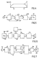
- Figure 4 is a graph which illustrates the error correcting performance of a convolutional code in terms of the bit error rate (BER) of convolutionally coded signals subjected to random transmission errors.
- the horizontal axis represents the bits being coded with the first one on the left and the vertical axis represents the bit error rate.
- the convolutional coder is assumed to have been reset to a known state at the beginning of the coding so that the first few coded bits have a low but increasing BER. By point A after approximately 10 to 12 coded bits the BER curve levels off and remains substantially constant for successive bits.
- the signal is first digitised to provide a number of digital parameters which represent a section in time of the signal. These parameters are then tree coded individually to produce a coded section of bits within which each coded parameter is wholly separable from the others. The coded section of bits may then be transmitted or stored.
- FIG. 5 shows a transmission system for channel coding digitised signals in which the parameters are encoded individually and transmitted over a radio link.
- a source of incoming analogue signals in this case a microphone 10, is coupled to an input to a Group Speciale Mobile (GSM) coder 12 which is operable to provide a set of parameters successively in time on a bus 14.
- GSM coder 12 provides a signal on a reset line 23 which signal is active at a point in time after each parameter has been made available on the bus 14.
- the bus 14 is coupled to a tree coder 22 to which the reset line 23 is also coupled.
- An output 24 from the coder is fed to a modulator 28 which supplies a modulated signal to a transmitter 30.
- the system operates to tree code and transmit each parameter generated by the GSM coder.
- the tree coder is a convolutional coder of the type shown in Figure 2
- the reset line 23 will be connected to the shift register to set the contents of S1,S2,S3 to known values - typically zeroes.
- the coding means 22 can be realised as a look-up table when the number of bits to be coded together is relatively small.
- the coding tree shown in Figure 3 may be implemented as a look-up table comprising a read only memory (ROM).
- ROM read only memory
- the look-up table contains all the possible permutations of the coding tree, for example location address 0110b contains 00110101b. When this look-up table is used to code fewer than four bits the most significant address lines are supplied with the reduced number of bits and the output is taken from the most significant bits of the data lines.
- the system shown in Figure 5 may be used as a trellis coder.
- Trellis coding is known per se and is disclosed in a paper "Channel Coding with Multilevel/Phase Signals" by Gottfried Ungerboeck, IEEE Transactions on Information Theory, Vol. IT-28, No. 1, January 1982. Such coding is applicable to 8 PSK and 16 QAM modulation systems and is described in detail subsequently.
- Any parameter-based analogue signal analysis means could be substituted for the GSM coder 12, for example a vocoder or a Code Excited Linear Prediction coding system.
- An incoming bit stream is assumed to be a garbled version of the encoded signal and this bit stream is subdivided into sections which correspond to the encoded bits of each parameter. Each of these sections is then compared with all of the possible sequences which could have been produced for that parameter by the encoder.
- a measure for example binary Hamming Distance or Euclidean Distance, is thus created of the likelihood that each of these possible sequences resulted in the section of the encoded signal and the most likely sequence chosen.
- Knowledge of the behaviour of the particular parameter being estimated may also be used to decide which of the possible sequences is the most likely.
- This knowledge may take the form of a probability density function table which contains values corresponding to the likelihood of occurrence of each of the possible sequences.
- ⁇ is the weighted average parameter value
- ⁇ is a value of the parameter which can vary between 0 and N-1
- P t ( ⁇ ) is the probability that the codeword corresponding to a parameter value of ⁇ was transmitted, given the particular sequence of bits which has been received
- P( ⁇ ) is the global probability that the codeword corresponding to a parameter value of ⁇ was transmitted, based upon known characteristics, or previous behaviour of the parameter.
- Figure 6 of the accompanying drawings shows a system for recreating analogue signals which have been tree encoded in accordance with the above encoding method described with reference to Figure 5 and then transmitted over a radio link.
- a radio receiver 52 having an antenna 50 is coupled to a demodulator 54 which subdivides an incoming bit stream into sections corresponding to encoded parameters.
- An output of the demodulator 54, which output comprises an encoded parameter, is coupled to one input to a comparison means 62 which has a second input coupled to a look-up table 64.
- the look-up table 64 contains all of the possible encoded sequences for the parameter being received.
- the comparator 62 may include a Hamming Distance measuring means and is operable to provide a measure of the probabilities that the encoded section of bits which has been received was caused by each of the possible encoded sequences.
- the output of the comparator 62 is fed to a selection means 70 which is operable to select the most likely parameter value from the plurality of probability values.
- the output of the selection means is fed to a resynthesiser 74 which is coupled to an audio output transducer 76.
- the resynthesiser stores successive parameters supplied to it by the means 70 and when a complete set has been received it provides a synthetic replica of the analogue signal originally coded to the audio output transducer 76.
- the means 70 may be replaced by means for calculating a weighted mean and this means may operate in a manner analogous to the equation described above.
- the comparator 62 may be arranged to exploit the tree structure of the coding process to almost halve its computational load. Instead of calculating the Hamming Distance in its entirety for each of the possible coder output sequences, the distance of the first two bits of the received section of coded bits from the two bits in each of the first two branches of the coding tree is measured. This process is repeated every time a codebook tree branch splits into two until a pair of bits representing the distance of the received bits from the roder output bits at every branch of the tree is obtained. All of the possible distances are then calculable by simple addition of all the distances at each branch of the tree.
- the efficiency of the tree or trellis coding needs to be considered.
- Figure 7 shows a system for digitising analogue signals at a lower bit-rate than that of Figure 5 and for transmitting the digitised signals via a radio link.
- a source of incoming analogue signals 10 is coupled to an input to a GSM coder 12 which is operable to provide a set of parameters successively in time on a bus 14.
- the bus 14 is coupled to a demultiplexer 16 which has two parallel digital output busses 18,20.
- the first of the digital outputs on the bus 18 comprises at least one most significant bit of each parameter and is fed to a tree coding means 22 which may be realised as a sequential circuit or as a look-up table.
- An output from the coding means 22 is fed via a bus 24 to a multiplexer 26.
- the multiplexer 26 is also fed with the remainder of the bits of each parameter from the output 20 of the demultiplexer 16.
- the demultiplexer 16 may simply comprise the separation of a multibit bus into two sets of digital bits and the multiplexer 24 may comprise the combination of two sets of digital bits to give a composite signal.
- An output of the multiplexer 26 is fed to a modem 28 whose output is fed to a transmitter (Tx) 30.
- the GSM coder 12 provides a set of digital parameters which are shown below together with their length in bits and one possible allocation for the number of bits of each which are fed to the coder 22 by the demultiplexer 16.
- LAR stands for Log Area Ratio
- LTP stands for Long Term Predictor.
- LAR1 to LAR8 are reflection coefficients transformed to Log Area Ratios.
- the long term predictor often referred to as the pitch predictor, computes optimum values of a loop gain and delay for minimising the residual signals within the GSM coder.
- Each of the parameters is coded separately and the coder 22 ( Figure 7) is reinitialised to a known point in the tree before the most significant bits to be coded are fed to it. This reinitialisation is performed upon all of the stages of the shift register at once and no outputs are taken from the terminals 40,42 ( Figure 2).
- the most significant bit of each parameter is coded first, followed by the second most significant bit, followed by the third most significant bit and so on. Referring to the BER graph shown in Figure 4, coding the bits in this order gives the most significant bit the most protection and decreasing amounts of protection for the less significant bits. Since the maximum number of bits coded for any one parameter is 7 the point A on the graph shown in Figure 4 is never reached and so in this case the BER remains below its maximum value.
- Figure 8 shows a system for recreating a synthetic version of an analogue signal which has been digitised and channel coded by a system such as that shown in Figure 7.
- a radio signal received at an antenna 50 is fed to a receiver (Rx) 52 having an output which is coupled to a demodulator 54.
- the output of the demodulator 54 is a serial stream of binary digits which is fed to a demultiplexer 56.
- the demultiplexer comprises a shift register to convert the serial binary data to a parallel format and to feed the tree coded section of each parameter on an output bus 58 to a comparator 62.
- the least significant bit or bits of each parameter which have not been tree coded are fed by the demultiplexer 56 on an output bus 60 to a multiplexer 72.
- the comparator 62 is also coupled to a coding means 64, which may comprise a look-up table.
- the purpose of the means 64 is to regenerate all the possible bit streams generated by the coding means 22 ( Figure 7).
- the comparator 62 is operable to measure the Hamming Distance, that is the number of bits which differ, between the received section of convolutionally coded bits and every possible sequence which the convolutional coder 22 ( Figure 7) could have produced.
- the Hamming Distances between the received section of coded bits and the coder sequences can be converted to a set of probabilities that each possible sequence is the one that was transmitted and this conversion to a probability may make the subsequent processing easier.
- Each of the possible sequences has a corresponding binary data value which is a possible value of the coded relevant section of a parameter.
- These Hamming Distances or their respective probabilities are then multiplied in a multiplier 66 by a value corresponding to the probability of the occurrence of that binary data value to which the coded sequence supplied by the means 64 corresponds.
- These probability values are held in a look-up table 68 whose output is fed to the multiplier 66. To reduce the computation required at this stage those parameter values having Hamming Distances of greater than a given value need not be fed to the multiplier 66.
- the output of the multiplier is fed to a selection means 70 which selects the lowest product of Hamming Distance and the probability of the occurrence of the binary data value.
- the selection means 70 could, for example, comprise a store means and a comparison means, for example a subtractor.
- the store means initially stores the first output of the multiplier 66 for a particular parameter.
- the output value held in the store means is then compared in the subtractor with the next output from the multiplier 66 and if this next value is lower than the one held in the store means then this next value is placed in the store means. This process is repeated until all the possible sequences have been compared.
- the binary data sequence which corresponds to the lowest Hamming Distance or greatest probability product is fed to the multiplexer 72.
- the multiplexer 72 is also supplied with the non-tree coded bits on a bus 60 and the output of the multiplexer is fed to a resynthesiser 74.
- the resynthesiser is also supplied with further parameters received and decoded by the system and provides a synthetic output signal to an output device such as a loudspeaker 76.
- Figure 9 shows a coding tree together with a graph of a probability density function (PDF) for the most significant bits of a parameter which have been coded using the tree. While the graph is shown as a smooth curve it will be understood that the PDF will be stored by the look-up table 68 ( Figure 8) as a set of discrete values. From the graph it can be seen that a value of the coded parameter of around 1001b is comparatively likely while a value of around 1111b is comparatively unlikely.
- PDF probability density function
- the probability density function stored in the look-up table 68 can be derived in at least two different ways. It could be a permanent read only memory (ROM) look-up table which contains values appropriate to the particular parameter of the analogue signals currently being recreated by the system. Alternatively the look-up table 68 could be an adaptive look-up table whose contents are altered during the operation of the system.
- Figure 10 shows a portion of the system shown in Figure 8 in which an adaptive means 78 has been coupled between an output of the selection means 70 and the look-up table 68. The means 78 is operable to alter the contents of the look-up table 68 based upon the current, and perhaps also previous, outputs from the selection means.
- the degree of the alteration may be varied from a slight change, for example a sharpening of the peak in the PDF graph, to a more drastic change in which a sharp peak is placed in the PDF graph centred upon the previous output of the means 70.
- Figure 11 gives an example of such a sharp peak in the PDF curve, centred upon a parameter value of 0101b. It is important not to allow the PDF curve to have a zero value anywhere because this may prevent a perfectly matched (zero Hamming Distance) sequence of received bits from being selected by the means 70.
- This sharp PDF curve may be particularly appropriate for recreating speech because it reduces the probability of the received parameter values from making wild excursions due to corrupted bits.
- the use of probability density functions in this manner can also be applied to the recreating system shown in Figure 6.
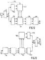
- Figure 12 shows a system for applying trellis coded modulation using 8 phase shift keying (TCA-8PSK) to the most significant bits of parameters provided by a speech coder.
- the transmitter includes a microphone 10 which is connected to a speech coder 12 for example a GSM speech coder.
- the digitised speech is supplied in a serial stream to a switch 80 which is activated on a bit by bit basis to connect those bits which are to be protected to a serial to parallel converter 82 and those bits which are to be left unprotected to a serial to parallel converter 84.
- the output of the converter 82 is taken 2 bits at a time and applied to a trellis encoder 22 which may be implemented as a DSP (digital signal processor), microprocessor or a dedicated gate array.
- the three bit parallel output of the trellis encoder 22 together with a three bit parallel output from the converter 84 are multiplexed in a multiplexer 26.
- the output from the multiplexer 26 is supplied to an 8PSK modulator 88, optionally by way of an interleaver 86.
- the output 90 of the modulator 88 is applied to a radio channel.
- the output comprises a codeword having appended synchronisation and address bits, which codeword occupies a particular time slot or physical channel in a TDMA frame.
- the trellis encoder 22 is also provided with a reset line 92 which resets the encoder to the beginning of the next parameter to be encoded.
- TCM-8PSK uses a 2/3 rate code applied to the basic 8PSK modulation.
- the corresponding net data ratio are 2 bits per symbol for the encoded bits and 3 bits per symbol for the uncoded bits.
- the modulator may be a 16QAM modulator in which case it will be necessary to have a 3/4 rate code applied to the 16QAM modulation.
- the corresponding net data rates are 3 bits per symbol for the encoded bits and 4 bits per symbol for the uncoded bits. This means that there will be 3 parallel output bits from the converter 82 and 4 parallel output bits from the converter 84.
- Figure 13 shows a receiver which in essence is the reciprocal of the transmitter shown in Figure 12.
- a recovered codeword on an input 92 is applied to either an 8PSK or a 16QAM demodulator 94, the parallel outputs from which are applied to a demultiplexer 56, if necessary, by way of a deinterleaver 96.
- the trellis encoded bits are supplied to a trellis decoder 98 which may incorporate a Viterbi algorithm and the uncoded bits are supplied to a parallel to series converter 100.
- the 2 bit (or 3 bit) outputs of the trellis decoder 98 are applied to a parallel to serial converter 102.
- the outputs of the converters 100,102 are applied to respective poles of a change-over switch 104 which is capable of being operated on a bit by bit basis.
- the switch 104 is so controlled that the more and less significant bits are assembled correctly for speech decoding in a speech decoder 74 to form an analogue signal which is applied to an audio output transducer 76.
- the receiver By encoding only the more significant bits of the digitised speech, the receiver need only decode those symbols representative of the trellis encoded digitised speech which saves an appreciable amount of power, up to 60%.
- Soft decision information may also be used in the signal recreating systems shown in Figures 6, 8 and 13. This well known technique involves the making of a weighted decision on each received bit at the demodulator. The output from the demodulator will then be a probability value for each bit rather than a one or a zero as it would be in a so called hard decision.
- One way of handling this information allows the Hamming Distance from the received section of coded bits to take a non-integer value.
- the multiplier 66 and the selection means 70 of Figure 8 must therefore be capable of working with non-integer values. Otherwise the system behaves exactly as previously described and the parameter value can either be selected or made equal to a weighted average.
Landscapes
- Physics & Mathematics (AREA)
- Probability & Statistics with Applications (AREA)
- Engineering & Computer Science (AREA)
- Theoretical Computer Science (AREA)
- Computer Networks & Wireless Communication (AREA)
- Signal Processing (AREA)
- Error Detection And Correction (AREA)
- Compression, Expansion, Code Conversion, And Decoders (AREA)
- Time-Division Multiplex Systems (AREA)
- Devices For Supply Of Signal Current (AREA)
- Transmission Systems Not Characterized By The Medium Used For Transmission (AREA)
Applications Claiming Priority (4)
| Application Number | Priority Date | Filing Date | Title |
|---|---|---|---|
| GB9100451 | 1991-01-09 | ||
| GB919100451A GB9100451D0 (en) | 1991-01-09 | 1991-01-09 | Digitising and recreating analogue signals |
| GB919106785A GB9106785D0 (en) | 1991-04-02 | 1991-04-02 | Channel coding digitised signals |
| GB9106785 | 1991-04-02 |
Publications (3)
| Publication Number | Publication Date |
|---|---|
| EP0494709A2 true EP0494709A2 (fr) | 1992-07-15 |
| EP0494709A3 EP0494709A3 (en) | 1993-10-13 |
| EP0494709B1 EP0494709B1 (fr) | 1998-05-27 |
Family
ID=26298239
Family Applications (1)
| Application Number | Title | Priority Date | Filing Date |
|---|---|---|---|
| EP92200003A Expired - Lifetime EP0494709B1 (fr) | 1991-01-09 | 1992-01-03 | Système de transmission de signal avec codage en arbre de chacun des paramètres |
Country Status (9)
| Country | Link |
|---|---|
| US (1) | US5233349A (fr) |
| EP (1) | EP0494709B1 (fr) |
| JP (1) | JP3238448B2 (fr) |
| KR (1) | KR100276780B1 (fr) |
| AU (1) | AU658597B2 (fr) |
| CA (1) | CA2058775C (fr) |
| CS (1) | CS3592A3 (fr) |
| DE (1) | DE69225619T2 (fr) |
| SG (1) | SG44761A1 (fr) |
Cited By (1)
| Publication number | Priority date | Publication date | Assignee | Title |
|---|---|---|---|---|
| EP1028533A1 (fr) * | 1999-02-09 | 2000-08-16 | Tandberg Television ASA | Décodage d'un signal d'entrée numérique |
Families Citing this family (21)
| Publication number | Priority date | Publication date | Assignee | Title |
|---|---|---|---|---|
| JP2676377B2 (ja) * | 1988-07-28 | 1997-11-12 | パイオニア株式会社 | ディスクプレーヤ |
| GB9105101D0 (en) * | 1991-03-11 | 1991-04-24 | British Telecomm | Error burst detection |
| US5528516A (en) * | 1994-05-25 | 1996-06-18 | System Management Arts, Inc. | Apparatus and method for event correlation and problem reporting |
| US5862190A (en) * | 1995-12-29 | 1999-01-19 | Motorola, Inc. | Method and apparatus for decoding an encoded signal |
| US20020021770A1 (en) * | 2000-05-03 | 2002-02-21 | Beerel Peter A. | Reduced-latency soft-in/soft-out module |
| US7171229B2 (en) * | 2001-10-31 | 2007-01-30 | Koninklijke Philips Electronics N.V. | Method for operating a radio communication system |
| US7139687B2 (en) * | 2001-12-31 | 2006-11-21 | The Mathworks, Inc. | Adaptive lookup table: a graphical simulation component for recursively updating numeric data stored in table form |
| EP1598941A4 (fr) * | 2003-02-03 | 2009-02-18 | Sharp Kk | Procede et dispositif de codage, procede et dispositif de decodage, programme et support d'enregistrement |
| US7379505B2 (en) * | 2003-02-13 | 2008-05-27 | Broadcom Corporation | Method and apparatus for performing trellis coded modulation of signals for transmission on a TDMA channel of a cable network |
| KR100692596B1 (ko) * | 2004-05-06 | 2007-03-13 | 삼성전자주식회사 | 수신 성능이 향상된 디지털 방송 송수신 시스템 및 그의신호처리방법 |
| KR100683879B1 (ko) * | 2004-05-06 | 2007-02-15 | 삼성전자주식회사 | 수신 성능이 향상된 디지털 방송 송수신 시스템 및 그의신호처리방법 |
| KR100744055B1 (ko) * | 2004-06-23 | 2007-07-30 | 삼성전자주식회사 | 수신 성능 및 등화 성능이 향상된 디지털 방송 송수신 시스템 및 그의 신호처리방법 |
| US20060133621A1 (en) * | 2004-12-22 | 2006-06-22 | Broadcom Corporation | Wireless telephone having multiple microphones |
| US20070116300A1 (en) * | 2004-12-22 | 2007-05-24 | Broadcom Corporation | Channel decoding for wireless telephones with multiple microphones and multiple description transmission |
| US20060147063A1 (en) * | 2004-12-22 | 2006-07-06 | Broadcom Corporation | Echo cancellation in telephones with multiple microphones |
| US8509703B2 (en) * | 2004-12-22 | 2013-08-13 | Broadcom Corporation | Wireless telephone with multiple microphones and multiple description transmission |
| US7599442B2 (en) * | 2005-01-20 | 2009-10-06 | Harris Corporation | Transmitter synchronization in a distributed transmission system |
| US20070071139A1 (en) * | 2005-09-23 | 2007-03-29 | Guner Arslan | Channel decoding using hard and soft decisions |
| US7639751B2 (en) * | 2006-04-04 | 2009-12-29 | Samsung Electronics Co., Ltd. | Advanced-VSB system (A-VSB) |
| US8259868B1 (en) | 2007-09-25 | 2012-09-04 | University Of Southern California | Conditionally cycle-free generalized tanner graphs based decoding |
| US8428661B2 (en) * | 2007-10-30 | 2013-04-23 | Broadcom Corporation | Speech intelligibility in telephones with multiple microphones |
Family Cites Families (5)
| Publication number | Priority date | Publication date | Assignee | Title |
|---|---|---|---|---|
| US4042927A (en) * | 1971-06-25 | 1977-08-16 | The United States Of America As Represented By The Secretary Of The Army | Ability of a monopulse radar to resolve and track jammers passively |
| GB2139458B (en) * | 1983-04-18 | 1986-10-01 | British Broadcasting Corp | Error correction in data transmission or processing |
| US4713829A (en) * | 1985-06-19 | 1987-12-15 | Codex Corporation | Coded modulation system with a simplified decoder capable of reducing the effects of channel distortion |
| FR2616986B1 (fr) * | 1987-06-17 | 1989-10-27 | Matra | Dispositif de decodage par syndromes de messages en code convolutionnel |
| US4968985A (en) * | 1988-06-06 | 1990-11-06 | Digital Equipment Corporation | Data demodulation system |
-
1992
- 1992-01-03 EP EP92200003A patent/EP0494709B1/fr not_active Expired - Lifetime
- 1992-01-03 DE DE69225619T patent/DE69225619T2/de not_active Expired - Fee Related
- 1992-01-03 SG SG1996007111A patent/SG44761A1/en unknown
- 1992-01-06 KR KR1019920000030A patent/KR100276780B1/ko not_active Expired - Fee Related
- 1992-01-06 CA CA002058775A patent/CA2058775C/fr not_active Expired - Fee Related
- 1992-01-07 US US07/817,580 patent/US5233349A/en not_active Expired - Fee Related
- 1992-01-07 AU AU10070/92A patent/AU658597B2/en not_active Ceased
- 1992-01-07 JP JP00106092A patent/JP3238448B2/ja not_active Expired - Fee Related
- 1992-01-07 CS CS9235A patent/CS3592A3/cs unknown
Cited By (1)
| Publication number | Priority date | Publication date | Assignee | Title |
|---|---|---|---|---|
| EP1028533A1 (fr) * | 1999-02-09 | 2000-08-16 | Tandberg Television ASA | Décodage d'un signal d'entrée numérique |
Also Published As
| Publication number | Publication date |
|---|---|
| KR920015765A (ko) | 1992-08-27 |
| EP0494709A3 (en) | 1993-10-13 |
| SG44761A1 (en) | 1997-12-19 |
| AU1007092A (en) | 1992-07-16 |
| JPH0548546A (ja) | 1993-02-26 |
| AU658597B2 (en) | 1995-04-27 |
| CA2058775C (fr) | 2003-08-05 |
| JP3238448B2 (ja) | 2001-12-17 |
| DE69225619D1 (de) | 1998-07-02 |
| EP0494709B1 (fr) | 1998-05-27 |
| DE69225619T2 (de) | 1998-12-24 |
| KR100276780B1 (ko) | 2001-01-15 |
| CS3592A3 (en) | 1992-07-15 |
| US5233349A (en) | 1993-08-03 |
| CA2058775A1 (fr) | 1992-07-10 |
Similar Documents
| Publication | Publication Date | Title |
|---|---|---|
| US5233349A (en) | Transmission and decoding of tree-encoded parameters of analogue signals | |
| US5968199A (en) | High performance error control decoder | |
| US5666370A (en) | High performance error control coding in channel encoders and decoders | |
| EP0712219B1 (fr) | Méthode et dispositif pour la détection d'un débit variable d'une transmission de données | |
| EP0116975B1 (fr) | Système de codage prédictif adapté à la parole | |
| KR100330336B1 (ko) | 2개의 블록 부호를 이용한 에러 정정 시스템 | |
| US5689511A (en) | Data receiver for receiving code signals having a variable data rate | |
| KR100554322B1 (ko) | 복수의 코딩 버스트내에 배치된 crc 비트에 의해 종료 상태가결정되는 컨벌루셔널 디코딩 | |
| US5784392A (en) | Viterbi decoder with l=2 best decoding paths | |
| Marcellin et al. | Predictive trellis coded quantization of speech | |
| US5398254A (en) | Error correction encoding/decoding method and apparatus therefor | |
| CA2131242C (fr) | Appareil de decodage pour systeme de transmission de donnees numeriques | |
| EP1805899B1 (fr) | Perforation/deperforation effectuees a l'aide d'une structure de perforation differentielle comprimee | |
| JP3154580B2 (ja) | ディジタル伝送装置 | |
| US5920593A (en) | Device for personal digital cellular telephones | |
| US20020031195A1 (en) | Method and apparatus for constellation decoder | |
| US7020223B2 (en) | Viterbi decoder and method using sequential two-way add-compare-select operations | |
| KR20010094694A (ko) | 티시엠 복호장치 및 방법 | |
| JP3445279B2 (ja) | データ伝送方法,データ伝送システムおよび送信装置,受信装置 | |
| Steele et al. | Statistical block protection coding for DPCM-AQF speech | |
| US20050141651A1 (en) | Method and system for modifying branch metric of Viterbi decoder for uncorrelated signals | |
| Zhu et al. | Results of generalized minimum distance decoding for block code of rate 1/2 | |
| JPH11243376A (ja) | 音声復号装置 |
Legal Events
| Date | Code | Title | Description |
|---|---|---|---|
| PUAI | Public reference made under article 153(3) epc to a published international application that has entered the european phase |
Free format text: ORIGINAL CODE: 0009012 |
|
| AK | Designated contracting states |
Kind code of ref document: A2 Designated state(s): DE ES FR GB IT |
|
| PUAL | Search report despatched |
Free format text: ORIGINAL CODE: 0009013 |
|
| AK | Designated contracting states |
Kind code of ref document: A3 Designated state(s): DE ES FR GB IT |
|
| 17P | Request for examination filed |
Effective date: 19940406 |
|
| 17Q | First examination report despatched |
Effective date: 19951211 |
|
| GRAG | Despatch of communication of intention to grant |
Free format text: ORIGINAL CODE: EPIDOS AGRA |
|
| GRAG | Despatch of communication of intention to grant |
Free format text: ORIGINAL CODE: EPIDOS AGRA |
|
| GRAH | Despatch of communication of intention to grant a patent |
Free format text: ORIGINAL CODE: EPIDOS IGRA |
|
| GRAH | Despatch of communication of intention to grant a patent |
Free format text: ORIGINAL CODE: EPIDOS IGRA |
|
| GRAA | (expected) grant |
Free format text: ORIGINAL CODE: 0009210 |
|
| AK | Designated contracting states |
Kind code of ref document: B1 Designated state(s): DE ES FR GB IT |
|
| PG25 | Lapsed in a contracting state [announced via postgrant information from national office to epo] |
Ref country code: ES Free format text: THE PATENT HAS BEEN ANNULLED BY A DECISION OF A NATIONAL AUTHORITY Effective date: 19980527 |
|
| REF | Corresponds to: |
Ref document number: 69225619 Country of ref document: DE Date of ref document: 19980702 |
|
| ITF | It: translation for a ep patent filed | ||
| RAP4 | Party data changed (patent owner data changed or rights of a patent transferred) |
Owner name: KONINKLIJKE PHILIPS ELECTRONICS N.V. Owner name: PHILIPS ELECTRONICS UK LIMITED |
|
| ET | Fr: translation filed | ||
| REG | Reference to a national code |
Ref country code: FR Ref legal event code: CD |
|
| PLBE | No opposition filed within time limit |
Free format text: ORIGINAL CODE: 0009261 |
|
| STAA | Information on the status of an ep patent application or granted ep patent |
Free format text: STATUS: NO OPPOSITION FILED WITHIN TIME LIMIT |
|
| 26N | No opposition filed | ||
| REG | Reference to a national code |
Ref country code: GB Ref legal event code: IF02 |
|
| PGFP | Annual fee paid to national office [announced via postgrant information from national office to epo] |
Ref country code: FR Payment date: 20030127 Year of fee payment: 12 |
|
| PGFP | Annual fee paid to national office [announced via postgrant information from national office to epo] |
Ref country code: GB Payment date: 20030131 Year of fee payment: 12 |
|
| PGFP | Annual fee paid to national office [announced via postgrant information from national office to epo] |
Ref country code: DE Payment date: 20030317 Year of fee payment: 12 |
|
| PG25 | Lapsed in a contracting state [announced via postgrant information from national office to epo] |
Ref country code: GB Free format text: LAPSE BECAUSE OF NON-PAYMENT OF DUE FEES Effective date: 20040103 |
|
| PG25 | Lapsed in a contracting state [announced via postgrant information from national office to epo] |
Ref country code: DE Free format text: LAPSE BECAUSE OF NON-PAYMENT OF DUE FEES Effective date: 20040803 |
|
| GBPC | Gb: european patent ceased through non-payment of renewal fee |
Effective date: 20040103 |
|
| PG25 | Lapsed in a contracting state [announced via postgrant information from national office to epo] |
Ref country code: FR Free format text: LAPSE BECAUSE OF NON-PAYMENT OF DUE FEES Effective date: 20040930 |
|
| REG | Reference to a national code |
Ref country code: FR Ref legal event code: ST |
|
| PG25 | Lapsed in a contracting state [announced via postgrant information from national office to epo] |
Ref country code: IT Free format text: LAPSE BECAUSE OF NON-PAYMENT OF DUE FEES;WARNING: LAPSES OF ITALIAN PATENTS WITH EFFECTIVE DATE BEFORE 2007 MAY HAVE OCCURRED AT ANY TIME BEFORE 2007. THE CORRECT EFFECTIVE DATE MAY BE DIFFERENT FROM THE ONE RECORDED. Effective date: 20050103 |