EP0494810A1 - Verfahren zur Erstellung eines statischen, elektromagnetischen Induktors - Google Patents
Verfahren zur Erstellung eines statischen, elektromagnetischen Induktors Download PDFInfo
- Publication number
- EP0494810A1 EP0494810A1 EP92400019A EP92400019A EP0494810A1 EP 0494810 A1 EP0494810 A1 EP 0494810A1 EP 92400019 A EP92400019 A EP 92400019A EP 92400019 A EP92400019 A EP 92400019A EP 0494810 A1 EP0494810 A1 EP 0494810A1
- Authority
- EP
- European Patent Office
- Prior art keywords
- coil
- pole
- block
- reel
- inductor
- Prior art date
- Legal status (The legal status is an assumption and is not a legal conclusion. Google has not performed a legal analysis and makes no representation as to the accuracy of the status listed.)
- Granted
Links
- 238000000034 method Methods 0.000 title claims description 18
- 238000004519 manufacturing process Methods 0.000 title claims description 14
- 230000003068 static effect Effects 0.000 title claims 3
- 230000008569 process Effects 0.000 title description 4
- XLYOFNOQVPJJNP-UHFFFAOYSA-N water Substances O XLYOFNOQVPJJNP-UHFFFAOYSA-N 0.000 claims abstract description 16
- 230000005284 excitation Effects 0.000 claims abstract description 9
- 238000004804 winding Methods 0.000 claims abstract description 6
- 230000005291 magnetic effect Effects 0.000 claims description 42
- 235000012431 wafers Nutrition 0.000 claims description 17
- 239000004020 conductor Substances 0.000 claims description 14
- 238000005470 impregnation Methods 0.000 claims description 10
- 239000011347 resin Substances 0.000 claims description 9
- 229920005989 resin Polymers 0.000 claims description 9
- 238000001816 cooling Methods 0.000 claims description 7
- 230000000903 blocking effect Effects 0.000 claims description 6
- 239000011810 insulating material Substances 0.000 claims description 5
- 230000002093 peripheral effect Effects 0.000 claims description 4
- 239000003302 ferromagnetic material Substances 0.000 claims 4
- 230000006835 compression Effects 0.000 claims 1
- 238000007906 compression Methods 0.000 claims 1
- 239000012530 fluid Substances 0.000 claims 1
- 230000000149 penetrating effect Effects 0.000 claims 1
- 238000007711 solidification Methods 0.000 claims 1
- 230000008023 solidification Effects 0.000 claims 1
- 229910000831 Steel Inorganic materials 0.000 abstract description 3
- 239000007788 liquid Substances 0.000 abstract description 3
- 230000002441 reversible effect Effects 0.000 abstract description 3
- 239000010959 steel Substances 0.000 abstract description 3
- 238000003756 stirring Methods 0.000 abstract description 3
- 238000005058 metal casting Methods 0.000 abstract 2
- 238000009749 continuous casting Methods 0.000 abstract 1
- 239000000498 cooling water Substances 0.000 description 5
- 238000005452 bending Methods 0.000 description 4
- 238000010276 construction Methods 0.000 description 3
- 238000009434 installation Methods 0.000 description 3
- 239000002184 metal Substances 0.000 description 3
- 229910052751 metal Inorganic materials 0.000 description 3
- 239000002245 particle Substances 0.000 description 3
- RYGMFSIKBFXOCR-UHFFFAOYSA-N Copper Chemical compound [Cu] RYGMFSIKBFXOCR-UHFFFAOYSA-N 0.000 description 2
- 238000010521 absorption reaction Methods 0.000 description 2
- 229910052802 copper Inorganic materials 0.000 description 2
- 239000010949 copper Substances 0.000 description 2
- 230000004907 flux Effects 0.000 description 2
- 238000009413 insulation Methods 0.000 description 2
- 239000000463 material Substances 0.000 description 2
- RONWGALEIBILOG-VMJVVOMYSA-N quinine sulfate Chemical compound [H+].[H+].[O-]S([O-])(=O)=O.C([C@H]([C@H](C1)C=C)C2)C[N@@]1[C@@H]2[C@H](O)C1=CC=NC2=CC=C(OC)C=C21.C([C@H]([C@H](C1)C=C)C2)C[N@@]1[C@@H]2[C@H](O)C1=CC=NC2=CC=C(OC)C=C21 RONWGALEIBILOG-VMJVVOMYSA-N 0.000 description 2
- 238000007789 sealing Methods 0.000 description 2
- 239000007787 solid Substances 0.000 description 2
- 208000031968 Cadaver Diseases 0.000 description 1
- 241000422252 Cales Species 0.000 description 1
- 229920000049 Carbon (fiber) Polymers 0.000 description 1
- 241000135309 Processus Species 0.000 description 1
- 241001080024 Telles Species 0.000 description 1
- 230000002159 abnormal effect Effects 0.000 description 1
- 230000032683 aging Effects 0.000 description 1
- 230000004888 barrier function Effects 0.000 description 1
- 239000004917 carbon fiber Substances 0.000 description 1
- 239000002131 composite material Substances 0.000 description 1
- 238000006731 degradation reaction Methods 0.000 description 1
- 238000005868 electrolysis reaction Methods 0.000 description 1
- 238000000605 extraction Methods 0.000 description 1
- 230000005294 ferromagnetic effect Effects 0.000 description 1
- 239000003365 glass fiber Substances 0.000 description 1
- 238000007654 immersion Methods 0.000 description 1
- 238000003780 insertion Methods 0.000 description 1
- 230000037431 insertion Effects 0.000 description 1
- 239000012774 insulation material Substances 0.000 description 1
- 238000002955 isolation Methods 0.000 description 1
- 230000007774 longterm Effects 0.000 description 1
- 230000007257 malfunction Effects 0.000 description 1
- 230000035515 penetration Effects 0.000 description 1
- 230000008439 repair process Effects 0.000 description 1
- 230000002123 temporal effect Effects 0.000 description 1
- 229920001187 thermosetting polymer Polymers 0.000 description 1
Images


Classifications
-
- H—ELECTRICITY
- H02—GENERATION; CONVERSION OR DISTRIBUTION OF ELECTRIC POWER
- H02K—DYNAMO-ELECTRIC MACHINES
- H02K3/00—Details of windings
- H02K3/46—Fastening of windings on the stator or rotor structure
- H02K3/52—Fastening salient pole windings or connections thereto
- H02K3/521—Fastening salient pole windings or connections thereto applicable to stators only
- H02K3/522—Fastening salient pole windings or connections thereto applicable to stators only for generally annular cores with salient poles
-
- H—ELECTRICITY
- H02—GENERATION; CONVERSION OR DISTRIBUTION OF ELECTRIC POWER
- H02K—DYNAMO-ELECTRIC MACHINES
- H02K9/00—Arrangements for cooling or ventilating
- H02K9/19—Arrangements for cooling or ventilating for machines with closed casing and closed-circuit cooling using a liquid cooling medium, e.g. oil
- H02K9/197—Arrangements for cooling or ventilating for machines with closed casing and closed-circuit cooling using a liquid cooling medium, e.g. oil in which the rotor or stator space is fluid-tight, e.g. to provide for different cooling media for rotor and stator
-
- H—ELECTRICITY
- H02—GENERATION; CONVERSION OR DISTRIBUTION OF ELECTRIC POWER
- H02K—DYNAMO-ELECTRIC MACHINES
- H02K2203/00—Specific aspects not provided for in the other groups of this subclass relating to the windings
- H02K2203/12—Machines characterised by the bobbins for supporting the windings
-
- Y—GENERAL TAGGING OF NEW TECHNOLOGICAL DEVELOPMENTS; GENERAL TAGGING OF CROSS-SECTIONAL TECHNOLOGIES SPANNING OVER SEVERAL SECTIONS OF THE IPC; TECHNICAL SUBJECTS COVERED BY FORMER USPC CROSS-REFERENCE ART COLLECTIONS [XRACs] AND DIGESTS
- Y10—TECHNICAL SUBJECTS COVERED BY FORMER USPC
- Y10T—TECHNICAL SUBJECTS COVERED BY FORMER US CLASSIFICATION
- Y10T29/00—Metal working
- Y10T29/49—Method of mechanical manufacture
- Y10T29/49002—Electrical device making
- Y10T29/49009—Dynamoelectric machine
-
- Y—GENERAL TAGGING OF NEW TECHNOLOGICAL DEVELOPMENTS; GENERAL TAGGING OF CROSS-SECTIONAL TECHNOLOGIES SPANNING OVER SEVERAL SECTIONS OF THE IPC; TECHNICAL SUBJECTS COVERED BY FORMER USPC CROSS-REFERENCE ART COLLECTIONS [XRACs] AND DIGESTS
- Y10—TECHNICAL SUBJECTS COVERED BY FORMER USPC
- Y10T—TECHNICAL SUBJECTS COVERED BY FORMER US CLASSIFICATION
- Y10T29/00—Metal working
- Y10T29/49—Method of mechanical manufacture
- Y10T29/49002—Electrical device making
- Y10T29/4902—Electromagnet, transformer or inductor
- Y10T29/49071—Electromagnet, transformer or inductor by winding or coiling
-
- Y—GENERAL TAGGING OF NEW TECHNOLOGICAL DEVELOPMENTS; GENERAL TAGGING OF CROSS-SECTIONAL TECHNOLOGIES SPANNING OVER SEVERAL SECTIONS OF THE IPC; TECHNICAL SUBJECTS COVERED BY FORMER USPC CROSS-REFERENCE ART COLLECTIONS [XRACs] AND DIGESTS
- Y10—TECHNICAL SUBJECTS COVERED BY FORMER USPC
- Y10T—TECHNICAL SUBJECTS COVERED BY FORMER US CLASSIFICATION
- Y10T29/00—Metal working
- Y10T29/49—Method of mechanical manufacture
- Y10T29/49002—Electrical device making
- Y10T29/4902—Electromagnet, transformer or inductor
- Y10T29/49073—Electromagnet, transformer or inductor by assembling coil and core
Definitions
- the present invention generally relates to the generation of a magnetic field, in particular a sliding or rotating mobile field. It applies more particularly, although not exclusively, to the case where this field is intended to stir a molten metal, such as that which constitutes the still liquid core of a steel product which is being cast and which solidifies progressively from its outer surface.
- the latter is produced by stacking flat sheets which have been cut so as to have a solid part and large teeth; in this case, by cylinder head construction and pole pieces are inseparable.
- This cooling can be internal.
- the water then circulates in the internal channel of a tubular conductor which constitutes the coil.
- This type of cooling requires the use of demineralized water and causes problems related to the need to make, within the limited volume which is available for the inductor, relatively complex and bulky hydraulic connections and to employ sufficiently powerful pumps.
- This life can also be reduced very significantly and localized (on a coil for example) by accidental phenomena (for example, introduction of a foreign body into the volume containing the coils, malfunction of the circuit d 'water).
- the first is to increase the overall life of the inductor.
- the second is to facilitate the replacement of a failed coil.
- the object of the present invention is in particular to solve these two problems simply and better than before.
- the description below corresponds to the production of a rotary field inductor, this inductor having a generally cylindrical shape and constituting a stirrer for the steel industry.
- the coils of this brewer are supplied with three-phase current.
- Its magnetic circuit is made up of a magnetic yoke and of added pole pieces.
- the implementation of the present invention involves the production of a coil and a coil support.
- FIG. 1 a simplified view of a prefabricated coil 1.
- This coil comprises an axial succession of wafers.
- Each wafer such as 40 is formed by an insulated conductor 2 wound in successive co-planar turns supported on a mandrel of shape not shown around a wafer axis not shown. It is then bent by curvature around a bending axis crossing the wafer axis at a right angle away from the wafer.
- the wafers are then stacked coaxially to a spool axis 3.
- Shims such as 42 maintain intervals, not shown, between the successive wafers for the passage of a liquid and, more particularly, of cooling water.
- the finished coil is in the form of a curved annular block.
- FIG. 2 A reel support is shown in FIG. 2.
- This reel support comprises a tubular reel barrel 4, of axis 5, at a base edge 4A from which an annular base 6 which rigidly connects extends from from this edge towards the outside of this barrel in directions substantially radial with respect to this barrel.
- the tubular coil barrel 4 and the base are preferably made of an insulating material with mechanical characteristics and thickness 6 sufficient for the assembly to behave in a perfectly rigid manner from its realization.
- this thickness is typically between 3 and 5 mm approximately, the material being composite, that is to say made up of glass or carbon fibers impregnated with a thermosetting resin.
- the external dimensions of the tubular barrel 4 correspond to the dimensions of the axial recess of the annular coil 1 taking account of a play distributed over the periphery of this barrel.
- the height of the barrel 4 (dimension taken along the direction of the axis 5 of the barrel) is equal to the height of the coil 1 (dimension taken along the direction of the axis of the coil 3), increased by the thickness of l 'annular base and two sets of mounting on the upper and lower faces of the coil 1.
- the inner wall of the coil drum 4 has, over its entire height, grooves 7 regularly arranged on this periphery.
- the radial extension of the annular base 6 corresponds to the radial extension of the external face of the coil 1 to which two games are added on either side.
- the reel 1 and the reel support having been produced, the following operations consist in threading the reel 1 around the reel barrel 4, positioning the reel so that its axis 3 coincides with the axis 5 of the tubular barrel 4, and to fix the reel on its reel support using shims and frets, in order to obtain an integral and relatively compact reel assembly.
- a hoop 11 is arranged which surrounds the spool and the spool support.
- This assembly then undergoes an impregnation operation carried out using a resin so as to keep the central recess. It then forms a coil block 32.
- This operation does not close the intervals between the turns of the coil, but it stiffens the shims and the hoops and gives the coil unit good mechanical resistance, good protection against immersion in water, as well as good insulation between turns and vis-à-vis the surrounding environment.
- FIG. 4 represents the view of a pole piece 12.
- This piece is produced by a stack of flat magnetic sheets which are clamped between two end plates 13 interconnected by a not shown tie rod.
- the external faces such as 13A of each of these plates are hollowed over their entire height by two parallelepiped grooves 14.
- the lower face 12A of this pole piece is provided with two internal threads 19 quine are not shown in this figure and which will be used for the mounting of this part on the internal bore of the cylinder head of the magnetic circuit (figure 6).
- a peripheral surface of this pole piece has external faces 13A of the plates 13 and two other faces 12C and 12D of this piece.
- the following assembly operation consists in threading the coil block as shown in FIG. 3 on the pole piece such that shown in Figure 4 and then fix it on this pole piece in order to obtain a pole block shown in Figure 5.
- the reel block is fixed to the pole piece 12 using reel block shims 15.
- These shims are removably interposed between the reel barrel 4 and the external surfaces of the end plates 13 of the part polar 12. They are provided with a clamping device which makes it possible to control their radial expansion, for example by axially driving in a corner using a screw.
- the screw of each shim being loosened, the shim can be freely slid between the coil drum 4 and the lateral surface of an end plate 13 of the pole piece 12, inside the groove 14 of this plate d 'end. When tightening this screw, the radial expansion of the shim ensures the mechanical blocking of the coil unit on the pole piece.
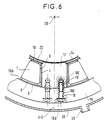
- the last phase of the assembly relates to the installation of the polar block on the internal bore of the cylinder head of the magnetic circuit 16.
- This cylinder head is constituted by a stack of magnetic sheets constituting a magnetic ring which surrounds the axis of the inductor 30 and has, with respect to this axis, an internal surface of cylindrical shape. This surface constitutes a pole surface 16A of this cylinder head and must receive the pole pieces.
- the inductor axis 30 is generally vertical, it being understood that the words such as upper and lower previously used have been used to facilitate the description and do not correspond to the final arrangement of the coils in the inductor.
- FIG. 6 represents a partial view of the inductor after mounting the pole block on the cylinder head 16.
- the mounting operation first passes through the orientation of the polar block to orient it as it should be later when it is ready to be assembled on the cylinder head (axis 5 of the pole piece perpendicular to the axis 30 of the cylinder head).
- each pole block is carried out using screws 18 which pass through the holes made in the magnetic yoke 16 and which are screwed inside. tapped holes 19 of the pole piece 12.
- These screws constitute connecting pieces having an operating head 18A in the vicinity of the external face of the cylinder head 16, a barrel 18B passing through this cylinder head and a foot 18C screwed into a pole piece 12 .
- This key can be made of an insulating material, or of a non-magnetic metal covered with an insulating material.
- the final assembly would be obtained by mounting the coil block as described above directly on a pole piece integrated into the cylinder head of the magnetic circuit, this part having the same provisions that the insert pole piece described with the help of figure 4. This case would correspond to the case of assembly n ° 1 previously indicated.
- the production method according to the present invention applies to all cases where the inductor consists of a magnetic circuit comprising a certain number of pole pieces and of prefabricated coils which must each be mounted coaxially on a pole piece.
Landscapes
- Engineering & Computer Science (AREA)
- Power Engineering (AREA)
- Mixers With Rotating Receptacles And Mixers With Vibration Mechanisms (AREA)
- Insulation, Fastening Of Motor, Generator Windings (AREA)
- Manufacture Of Motors, Generators (AREA)
- Coils Or Transformers For Communication (AREA)
- Financial Or Insurance-Related Operations Such As Payment And Settlement (AREA)
- Magnetic Resonance Imaging Apparatus (AREA)
- Continuous Casting (AREA)
- Electromagnets (AREA)
- Coils Of Transformers For General Uses (AREA)
- Heat Treatment Of Articles (AREA)
Applications Claiming Priority (2)
| Application Number | Priority Date | Filing Date | Title |
|---|---|---|---|
| FR9100297 | 1991-01-11 | ||
| FR9100297A FR2671677A1 (fr) | 1991-01-11 | 1991-01-11 | Procede de realisation d'un inducteur electromagnetique. |
Publications (2)
| Publication Number | Publication Date |
|---|---|
| EP0494810A1 true EP0494810A1 (de) | 1992-07-15 |
| EP0494810B1 EP0494810B1 (de) | 1995-10-18 |
Family
ID=9408614
Family Applications (1)
| Application Number | Title | Priority Date | Filing Date |
|---|---|---|---|
| EP92400019A Expired - Lifetime EP0494810B1 (de) | 1991-01-11 | 1992-01-06 | Verfahren zur Erstellung eines statischen, elektromagnetischen Induktors |
Country Status (7)
| Country | Link |
|---|---|
| US (1) | US5285563A (de) |
| EP (1) | EP0494810B1 (de) |
| JP (1) | JP3217422B2 (de) |
| AT (1) | ATE129365T1 (de) |
| CA (1) | CA2059081C (de) |
| DE (1) | DE69205445T2 (de) |
| FR (1) | FR2671677A1 (de) |
Cited By (1)
| Publication number | Priority date | Publication date | Assignee | Title |
|---|---|---|---|---|
| WO2010136206A3 (de) * | 2009-05-29 | 2011-08-18 | Brose Fahrzeugteile Gmbh & Co. Kg, Würzburg | Stator für einen elektromotor |
Families Citing this family (21)
| Publication number | Priority date | Publication date | Assignee | Title |
|---|---|---|---|---|
| DE59604144D1 (de) * | 1995-02-21 | 2000-02-17 | Siemens Ag | Hybriderregte elektrische Maschine |
| US5859482A (en) * | 1997-02-14 | 1999-01-12 | General Electric Company | Liquid cooled electric motor frame |
| DE20115471U1 (de) | 2001-09-19 | 2003-02-20 | Biester, Klaus, 29342 Wienhausen | Universelles Energieversorgungssystem |
| DE20115474U1 (de) * | 2001-09-19 | 2003-02-20 | Biester, Klaus, 29342 Wienhausen | Gleichspannungs-Wandlervorrichtung |
| DE20018560U1 (de) * | 2000-10-30 | 2002-03-21 | CAMERON GmbH, 29227 Celle | Steuer- und Versorgungssystem |
| DE20115473U1 (de) * | 2001-09-19 | 2003-02-20 | Biester, Klaus, 29342 Wienhausen | Universelles Energieversorgungssystem |
| US7615893B2 (en) * | 2000-05-11 | 2009-11-10 | Cameron International Corporation | Electric control and supply system |
| IL140246A (en) * | 2000-12-12 | 2007-09-20 | Pavel Dvoskin | Treatment of molten metals by moving an electric arc during aggregation |
| DE10046030C2 (de) * | 2000-09-18 | 2002-11-07 | Zf Sachs Ag | Wickelkörper zur Aufnahme einer Wicklung für einen elektro-magneto-mechanischen Wandler sowie elektro-magneto-mechanischer Wandler |
| EP1235325A1 (de) * | 2001-02-16 | 2002-08-28 | Chun-Pu Hsu | Verbundstatoraufbau |
| US6679067B1 (en) | 2001-07-16 | 2004-01-20 | C W Holdings Llc | Cryogenic processes for treating pantyhose |
| IL144422A0 (en) * | 2001-07-18 | 2002-05-23 | Netanya Plasmatec Ltd | Riser(s) size reduction and/or metal quality improving in gravity casting of shaped products by moving electric arc |
| IL145099A0 (en) * | 2001-08-23 | 2002-06-30 | Netanya Plasmatec Ltd | Method and apparatus for stirring and treating continuous and semi continuous metal casting |
| DE20115475U1 (de) * | 2001-09-19 | 2003-02-20 | Biester, Klaus, 29342 Wienhausen | Gleichspannungs-Wandlervorrichtung |
| US7020271B2 (en) * | 2003-06-12 | 2006-03-28 | Barbara Isabel Hummel | Ring control device |
| US20060255679A1 (en) * | 2005-05-13 | 2006-11-16 | Dine Pieter V | Apparatus for pole pieces |
| JP4851806B2 (ja) * | 2006-02-16 | 2012-01-11 | 澤藤電機株式会社 | 回転電機用電機子及び電機子の製造方法 |
| KR101476022B1 (ko) * | 2010-05-26 | 2014-12-24 | 도요타지도샤가부시키가이샤 | 고정자 제조 방법 |
| JP5727577B2 (ja) * | 2013-11-11 | 2015-06-03 | ファナック株式会社 | コイル固定部品を備える電動機の固定子、電動機、及び単位コイルの固定方法 |
| US10110080B2 (en) * | 2015-11-30 | 2018-10-23 | Caterpillar Inc. | Coil and stator assembly of a rotary electric machine |
| KR20250138994A (ko) | 2024-03-14 | 2025-09-23 | (주)디엔에프 | 실리콘 화합물 및 이를 이용하는 실리콘 함유 박막의 제조방법 |
Citations (3)
| Publication number | Priority date | Publication date | Assignee | Title |
|---|---|---|---|---|
| US2655613A (en) * | 1952-01-24 | 1953-10-13 | Allis Louis Co | Rotor for dynamoelectric machines |
| GB773665A (en) * | 1954-11-24 | 1957-05-01 | Gen Electric Canada | Improvements in and relating to salient pole dynamo electric machines |
| WO1989006874A1 (en) * | 1988-01-22 | 1989-07-27 | Prestolite Electric Incorporated | Field assembly insulator |
Family Cites Families (3)
| Publication number | Priority date | Publication date | Assignee | Title |
|---|---|---|---|---|
| JPS57139914A (en) * | 1981-02-20 | 1982-08-30 | Mitsubishi Electric Corp | Manufacture of insulated coil |
| JPS59159677A (ja) * | 1983-02-28 | 1984-09-10 | Toshiba Corp | 電磁撹拌器 |
| US4990810A (en) * | 1989-07-18 | 1991-02-05 | Westinghouse Electric Corp. | Coil carrier fixture and field coil carrier assembly |
-
1991
- 1991-01-11 FR FR9100297A patent/FR2671677A1/fr not_active Withdrawn
-
1992
- 1992-01-06 DE DE69205445T patent/DE69205445T2/de not_active Expired - Fee Related
- 1992-01-06 AT AT92400019T patent/ATE129365T1/de not_active IP Right Cessation
- 1992-01-06 EP EP92400019A patent/EP0494810B1/de not_active Expired - Lifetime
- 1992-01-07 US US07/817,624 patent/US5285563A/en not_active Expired - Lifetime
- 1992-01-10 JP JP02214992A patent/JP3217422B2/ja not_active Expired - Fee Related
- 1992-01-10 CA CA002059081A patent/CA2059081C/fr not_active Expired - Fee Related
Patent Citations (3)
| Publication number | Priority date | Publication date | Assignee | Title |
|---|---|---|---|---|
| US2655613A (en) * | 1952-01-24 | 1953-10-13 | Allis Louis Co | Rotor for dynamoelectric machines |
| GB773665A (en) * | 1954-11-24 | 1957-05-01 | Gen Electric Canada | Improvements in and relating to salient pole dynamo electric machines |
| WO1989006874A1 (en) * | 1988-01-22 | 1989-07-27 | Prestolite Electric Incorporated | Field assembly insulator |
Non-Patent Citations (3)
| Title |
|---|
| PATENT ABSTRACTS OF JAPAN vol. 6, no. 238 (E-114)(1116) 26 Novembre 1982 & JP-A-57 139 914 ( MITSUBISHI ) 30 Août 1982 * |
| PATENT ABSTRACTS OF JAPAN vol. 9, no. 10 (E-290)(1733) 17 Janvier 1985 & JP-A-59 159 677 ( TOSHIBA ) 10 Septembre 1984 * |
| SOVIET INVENTIONS ILLUSTRATED Section R, week B08, 4 avril 1979 Derwent Publications Ltd., London GB. * |
Cited By (2)
| Publication number | Priority date | Publication date | Assignee | Title |
|---|---|---|---|---|
| WO2010136206A3 (de) * | 2009-05-29 | 2011-08-18 | Brose Fahrzeugteile Gmbh & Co. Kg, Würzburg | Stator für einen elektromotor |
| KR101335041B1 (ko) * | 2009-05-29 | 2013-11-29 | 브로제 파르초이크타일레 게엠베하 운트 코. 카게, 뷔르츠부르크 | 전기 모터용 고정자 |
Also Published As
| Publication number | Publication date |
|---|---|
| DE69205445T2 (de) | 1996-04-04 |
| CA2059081A1 (fr) | 1992-07-12 |
| FR2671677A1 (fr) | 1992-07-17 |
| JPH0823652A (ja) | 1996-01-23 |
| EP0494810B1 (de) | 1995-10-18 |
| ATE129365T1 (de) | 1995-11-15 |
| US5285563A (en) | 1994-02-15 |
| DE69205445D1 (de) | 1995-11-23 |
| CA2059081C (fr) | 2003-09-09 |
| JP3217422B2 (ja) | 2001-10-09 |
Similar Documents
| Publication | Publication Date | Title |
|---|---|---|
| EP0494810B1 (de) | Verfahren zur Erstellung eines statischen, elektromagnetischen Induktors | |
| EP0097590B1 (de) | Magnetische Lagerung für einen Rotor in einer wasserdichten Umgebung | |
| EP3627659B1 (de) | Rotor für asynchrone elektrische maschine mit nicht durchgehender welle | |
| EP1924415B1 (de) | Vorrichtung zum umwandeln von material unter verwendung von induktionserwärmung | |
| EP1499001A1 (de) | Kühlvorrichtung für eine elektrische Maschine insbesondere für eine Synchronmaschine mit Dauermagneten | |
| FR2514965A1 (fr) | Machine electrique synchrone a inducteur supraconducteur | |
| EP2297838B1 (de) | Laüfer einer synchronen elektrischen mehrpolarmaschine mit schenkelpolen | |
| FR2502996A1 (fr) | Inducteur electromagnetique a champ tournant et equipement de lingotiere de coulee continue des metaux pour son utilisation | |
| FR3054386A1 (fr) | Carcasse de stator de moteur vissee et procede correspondant | |
| FR2931316A1 (fr) | Rotor d'une machine electrique synchrone multipolaire a poles saillants | |
| EP2584210B1 (de) | Verkleideter Stator einer elektromagnetischen Maschine für korrosive Umgebungen ohne Wärmebehandlung | |
| CA2835787C (fr) | Turbine generatrice de courant electrique | |
| EP2367264A1 (de) | Rotierende elektrische Maschine mit Stator mit konzentrierten Wicklungen | |
| EP3737901B1 (de) | Kalttiegel und zugehöriger kühlverteiler für eine induktionsheizvorrichtung | |
| EP3198617A1 (de) | Magnetkern eines rotierenden transformators | |
| FR2635618A1 (fr) | Rotor de machine electrique a enroulements d'excitation supraconducteurs | |
| EP0095962A1 (de) | Verfahren zur Formung von Wickelköpfen am Stator eines elektrischen Motors und gemäss diesem Verfahren hergestellter Stator eines Elektromotors | |
| FR3074705A1 (fr) | Procedes de formage/soudage de pieces par impulsion magnetique | |
| FR2589643A1 (fr) | Rotor pour une machine electrique rotative supraconductrice | |
| WO1999062306A1 (fr) | Procede de modulation de la configuration d'un champ magnetique | |
| FR2769424A1 (fr) | Moteur synchrone comportant un rotor a aimants permanents | |
| FR2513710A1 (fr) | Ensemble d'entrainement synchrone par voie magnetique avec cloison separatrice feuilletee | |
| CH405536A (fr) | Procédé pour souder bout à bout deux tubes depuis l'intérieur et torche de soudure à l'arc électrique pour la mise en oeuvre de ce procédé | |
| FR3142629A1 (fr) | Machine électrique avec refroidissement direct des passages radiaux dans le corps de stator | |
| EP2673961A1 (de) | Magnetmotorvorrichtung eines elektrodynamischen wandlers |
Legal Events
| Date | Code | Title | Description |
|---|---|---|---|
| PUAI | Public reference made under article 153(3) epc to a published international application that has entered the european phase |
Free format text: ORIGINAL CODE: 0009012 |
|
| AK | Designated contracting states |
Kind code of ref document: A1 Designated state(s): AT CH DE FR GB IT LI LU SE |
|
| 17P | Request for examination filed |
Effective date: 19921210 |
|
| 17Q | First examination report despatched |
Effective date: 19940630 |
|
| GRAA | (expected) grant |
Free format text: ORIGINAL CODE: 0009210 |
|
| AK | Designated contracting states |
Kind code of ref document: B1 Designated state(s): AT CH DE FR GB IT LI LU SE |
|
| REF | Corresponds to: |
Ref document number: 129365 Country of ref document: AT Date of ref document: 19951115 Kind code of ref document: T |
|
| ITF | It: translation for a ep patent filed | ||
| REF | Corresponds to: |
Ref document number: 69205445 Country of ref document: DE Date of ref document: 19951123 |
|
| GBT | Gb: translation of ep patent filed (gb section 77(6)(a)/1977) |
Effective date: 19951216 |
|
| PLBE | No opposition filed within time limit |
Free format text: ORIGINAL CODE: 0009261 |
|
| STAA | Information on the status of an ep patent application or granted ep patent |
Free format text: STATUS: NO OPPOSITION FILED WITHIN TIME LIMIT |
|
| 26N | No opposition filed | ||
| REG | Reference to a national code |
Ref country code: GB Ref legal event code: IF02 |
|
| PGFP | Annual fee paid to national office [announced via postgrant information from national office to epo] |
Ref country code: LU Payment date: 20090115 Year of fee payment: 18 Ref country code: AT Payment date: 20090115 Year of fee payment: 18 |
|
| PGFP | Annual fee paid to national office [announced via postgrant information from national office to epo] |
Ref country code: DE Payment date: 20090122 Year of fee payment: 18 |
|
| PGFP | Annual fee paid to national office [announced via postgrant information from national office to epo] |
Ref country code: GB Payment date: 20090122 Year of fee payment: 18 Ref country code: CH Payment date: 20090115 Year of fee payment: 18 |
|
| PGFP | Annual fee paid to national office [announced via postgrant information from national office to epo] |
Ref country code: SE Payment date: 20090114 Year of fee payment: 18 Ref country code: IT Payment date: 20090126 Year of fee payment: 18 |
|
| PGFP | Annual fee paid to national office [announced via postgrant information from national office to epo] |
Ref country code: FR Payment date: 20090115 Year of fee payment: 18 |
|
| REG | Reference to a national code |
Ref country code: CH Ref legal event code: PL |
|
| GBPC | Gb: european patent ceased through non-payment of renewal fee |
Effective date: 20100106 |
|
| EUG | Se: european patent has lapsed | ||
| REG | Reference to a national code |
Ref country code: FR Ref legal event code: ST Effective date: 20100930 |
|
| PG25 | Lapsed in a contracting state [announced via postgrant information from national office to epo] |
Ref country code: LI Free format text: LAPSE BECAUSE OF NON-PAYMENT OF DUE FEES Effective date: 20100131 Ref country code: FR Free format text: LAPSE BECAUSE OF NON-PAYMENT OF DUE FEES Effective date: 20100201 Ref country code: CH Free format text: LAPSE BECAUSE OF NON-PAYMENT OF DUE FEES Effective date: 20100131 |
|
| PG25 | Lapsed in a contracting state [announced via postgrant information from national office to epo] |
Ref country code: DE Free format text: LAPSE BECAUSE OF NON-PAYMENT OF DUE FEES Effective date: 20100803 Ref country code: AT Free format text: LAPSE BECAUSE OF NON-PAYMENT OF DUE FEES Effective date: 20100106 |
|
| PG25 | Lapsed in a contracting state [announced via postgrant information from national office to epo] |
Ref country code: GB Free format text: LAPSE BECAUSE OF NON-PAYMENT OF DUE FEES Effective date: 20100106 |
|
| PG25 | Lapsed in a contracting state [announced via postgrant information from national office to epo] |
Ref country code: IT Free format text: LAPSE BECAUSE OF NON-PAYMENT OF DUE FEES Effective date: 20100106 |
|
| PG25 | Lapsed in a contracting state [announced via postgrant information from national office to epo] |
Ref country code: SE Free format text: LAPSE BECAUSE OF NON-PAYMENT OF DUE FEES Effective date: 20100107 Ref country code: LU Free format text: LAPSE BECAUSE OF NON-PAYMENT OF DUE FEES Effective date: 20100106 |