EP0495295A2 - Système de commande de papillon pour moteur à combustion dans un véhicule - Google Patents
Système de commande de papillon pour moteur à combustion dans un véhicule Download PDFInfo
- Publication number
- EP0495295A2 EP0495295A2 EP91310734A EP91310734A EP0495295A2 EP 0495295 A2 EP0495295 A2 EP 0495295A2 EP 91310734 A EP91310734 A EP 91310734A EP 91310734 A EP91310734 A EP 91310734A EP 0495295 A2 EP0495295 A2 EP 0495295A2
- Authority
- EP
- European Patent Office
- Prior art keywords
- throttle valve
- control
- control system
- signal
- actuator
- Prior art date
- Legal status (The legal status is an assumption and is not a legal conclusion. Google has not performed a legal analysis and makes no representation as to the accuracy of the status listed.)
- Granted
Links
- 230000004044 response Effects 0.000 claims abstract description 13
- 230000015654 memory Effects 0.000 claims description 15
- 230000008859 change Effects 0.000 claims description 2
- 238000000034 method Methods 0.000 claims description 2
- 230000008569 process Effects 0.000 claims description 2
- 230000000694 effects Effects 0.000 abstract description 4
- 238000013459 approach Methods 0.000 abstract 1
- 238000002485 combustion reaction Methods 0.000 description 3
- 238000010586 diagram Methods 0.000 description 2
- 239000012530 fluid Substances 0.000 description 2
- 230000006870 function Effects 0.000 description 2
- 230000008901 benefit Effects 0.000 description 1
- 239000000446 fuel Substances 0.000 description 1
- 230000006872 improvement Effects 0.000 description 1
Images

Classifications
-
- F—MECHANICAL ENGINEERING; LIGHTING; HEATING; WEAPONS; BLASTING
- F02—COMBUSTION ENGINES; HOT-GAS OR COMBUSTION-PRODUCT ENGINE PLANTS
- F02D—CONTROLLING COMBUSTION ENGINES
- F02D11/00—Arrangements for, or adaptations to, non-automatic engine control initiation means, e.g. operator initiated
- F02D11/06—Arrangements for, or adaptations to, non-automatic engine control initiation means, e.g. operator initiated characterised by non-mechanical control linkages, e.g. fluid control linkages or by control linkages with power drive or assistance
- F02D11/10—Arrangements for, or adaptations to, non-automatic engine control initiation means, e.g. operator initiated characterised by non-mechanical control linkages, e.g. fluid control linkages or by control linkages with power drive or assistance of the electric type
- F02D2011/101—Arrangements for, or adaptations to, non-automatic engine control initiation means, e.g. operator initiated characterised by non-mechanical control linkages, e.g. fluid control linkages or by control linkages with power drive or assistance of the electric type characterised by the means for actuating the throttles
- F02D2011/102—Arrangements for, or adaptations to, non-automatic engine control initiation means, e.g. operator initiated characterised by non-mechanical control linkages, e.g. fluid control linkages or by control linkages with power drive or assistance of the electric type characterised by the means for actuating the throttles at least one throttle being moved only by an electric actuator
Definitions
- This invention relates to a throttle valve control system and in particular to an electronic throttle valve control system for the internal combustion engine of a motor vehicle.
- the system including means to sense the actual position of the throttle valve and provide a signal indicative thereof, means to provide a signal indicative of a required throttle valve position and means to compare said signals indicative of actual and required throttle valve position and to provide a controlling signal to a throttle valve actuator means to adjust the throttle valve position accordingly.
- a throttle valve control system for an engine of a vehicle having a throttle valve rotatably mounted in an inlet passage of the engine, the control system comprising a throttle valve sensing means to provide a signal indicative of the rotational position of the throttle valve, an input means to provide a signal indicative of a desired throttle valve rotational position, a control means having comparator means to compare the signals received from the sensing means and the input means and a controller means to process the error signal from the comparator means and provide a control signal to an actuator means to vary the angular position of the throttle valve between a closed position and an open position in response to said control signal received from the control means wherein when the signal received from the sensing means indicates that the throttle valve is within a predetermined range measured from the closed position and the error signal resulting from the comparison of the signals from the sensing means and the input means indicates that a change in throttle valve opening is required then the control signal sent to the actuator is greater than would normally be sent to the actuator for such an error signal.
- the control means may include a proportional control means.
- the control means may include an integral control means.
- control means is a three term proportional, integral and derivative controller.
- the gain of the system may be increased by a factor of up to 3 times its normal value when the throttle valve is within a predetermined range of 0 to 10 degrees from the throttle valve closed position.
- control means gain is constant above said predetermined range and is increased linearly as the throttle valve is closed within said predetermined range.
- the control signal D to the actuator means may be equal to Where
- the control means may be a central processing unit (CPU) having at least one read only memory location (ROM) and one random access memory location (RAM), the system gain being stored digitally in the or one of the read only memory locations in the form of a look up table.
- CPU central processing unit
- ROM read only memory location
- RAM random access memory location
- the greater than normal control signal may be in the form of a predetermined control signal to the actuator means, the comparator means being temporarily bypassed.
- control means may be a central processing unit having at least one read only memory location (ROM) and at least one random access memory location (RAM) the predetermined control signal being stored digitally in the or one of the read only memory locations.
- ROM read only memory location
- RAM random access memory location
- the input means may be a driver operable input means in the form of a potentiometer attached to an accelerator pedal of the vehicle.
- the input means could be an idle speed control unit.
- the input means may be switchable between the potentiometer and the idle speed control unit.
- the control system may be operable such that when the throttle valve is open in a first range less than 2 degrees from its closed position then the comparator means is temporarily bypassed and a predetermined control signal is sent to the actuator means and when the throttle valve is open in a second range between 2 and 10 degrees the control signal sent to the actuator means is proportionally greater for the same error signal than when the throttle valve is open in a third range more than 10 degrees from its closed position.
- control means may be a central processing unit having at least two read only memories locations (ROMs) and at least one random access memory location, one of the read only memory locations being used to store the predetermined control signal and another of the read only memory locations being used to store a system look up table used to increase the control signal in said second range.
- ROMs read only memories locations
- the actuator means may be an electric motor.
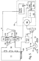
- FIG. 4 there is shown an internal combustion engine 11 of a motor vehicle (not shown), the engine 11 having an inlet manifold 12 defining an inlet tract 13 in which is rotatably mounted a disc throttle valve 14.
- the disc throttle valve 14 is rotatable through approximately 90 degrees from a closed position where it obscures the inlet tract 13 to an open position where it provides little restriction to the flow of fluid through the inlet tract 13.
- the throttle valve opening is measured from the closed position in terms of degrees of rotation or percentage open, therefor 10 percent open is approximately equal to a rotation of 9 degrees from the closed position.
- the throttle valve 14 is rotated by an actuator means in the form of an electric motor 15 connected to a spindle 8 of the throttle valve 14, the spindle 8 being supported by two plain bearings 9.
- a throttle valve sensing means in the form of a rotary potentiometer 30.
- a control means 21 is connected to the motor 15, potentiometer 30 and also to an input means in the form of a position sensor 31 connected to an accelerator pedal 16 or the motor vehicle.
- the accelerator pedal 16 is rotationally connected to part of the body 10 of the motor vehicle by pivot means (not shown).
- the control means 21 comprise a proportional, integral and derivative controller (P.I.D.) 22, a motor driver power amplifying device 23, a gain control device 24, a step input device 25, a comparator 26 and changeover switching means 28.
- P.I.D. proportional, integral and derivative controller
- the control means 21 is essentially a central processing unit having a number of random access memory locations (RAMs) and read only memory locations (ROMs) associated therewith to form a microcomputer.
- RAMs random access memory locations
- ROMs read only memory locations
- the signal 'E' passes to the P.I.D. controller 22 which operates according to the general transfer function
- the output signal 'O' being supplied to the gain control device 24.
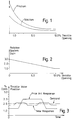
- the gain control device 24 includes a read only memory (ROM) in which is stored a look up table of gain 'K' against throttle position 'P' a part of which is shown in graphical form in Figure 2.
- ROM read only memory
- the gain control device 24 receives a signal indicative of actual throttle valve position which is used to address the correct part of the look up table.
- the gain control device 24 take the signal 'O' and factors it by the gain 'k' from the look up table so that a control signal 'd' is sent to the motor driver 23 via the switching means 28.
- K could be 50 for throttle openings of 10 degrees and above which would mean a maximum circuit gain of 150.
- control means 21 operates the changeover switch 28 engaging the step input device 25 and bypassing the comparator 26.
- the step input device 25 produces a predetermined control signal 'e' which is stored in a read only memory in digital form to the motor driver 23.
- the predetermined control signal 'e' is several times greater than the error signal 'E' which would be present due to such a small throttle valve opening and is of magnitude sufficient to provide a control signal 'D' to the motor 15 less than but near to the signal level required to overcome the stiction associated with the control valve A.
- the throttle valve 14 will tend to hunt because the integrator part of the P.I.D. controller will integrate the small error signal 'E' until the drive 'D' to the motor 15 is sufficient to break the stiction present. The throttle valve 14 will then overshoot the desired position and will remain open too much until the integrator has ramped down sufficient to allow the motor 15 to urge the throttle valve 14 closed.
- the amount of overshoot and frequency response of the throttle valve system is increased by the increase in system gain introduced by the gain control device 24 within a predetermined range of 0 to 10 degrees from the closed position.
- the control signal D sent to the motor 15 for small throttle valve openings is greater due to the effect of the gain control device 24 than it would normally be, causing the integrator part of the P.I.D. controller 22 to ramp up and down more quickly.
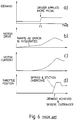
- FIGS. 6a - d show the response of a prior art throttle control system without a step input device or gain control.
- the driver applying a demand for a small throttle opening at zero time by means of the accelerator pedal due to the slow speed at which the integrator part of the P.I.D. controller operates there is no movement of the throttle valve as shown in Figure 6d and so the driver at time T1 increases the demand for throttle opening which causes the motor to suddenly overcome the stiction associated with the throttle valve 14 and rapidly open the throttle valve 14 overshooting the desired throttle opening.
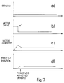
- the step input device 25 sensing a small throttle opening and a small accelerator pedal 16 demand operates the switch 28 to allow a step input of magnitude 'e' to the motor driver 23.
- the step input device 25 is disabled by means of the switch 28 allowing the normal error signal 'd' to reach the motor driver 23.
- the effect of the step input device 25 is to send a short pulse of power to the motor 15 of sufficient magnitude to overcome stiction.
- Figure 7d shows the response to a step input from the accelerator pedal 16 as shown in Figure 7a.
- FIG. 5 there is shown a second embodiment of the invention which is similar in many respects to the first embodiment just described.
- Figure 5 shows an internal combustion engine 111 of a motor vehicle (not shown), the engine 111 having an inlet manifold 112 defining an inlet tract 113 in which is rotatably mounted a disc throttle valve 114.
- the disc throttle valve 114 is rotatable through approximately 90 degrees from a closed position, where it obscures the inlet tract 13, to an open position where it provides little restriction to the flow of fluid through the inlet tract.
- throttle valve opening is measured from the closed position in terms of degrees of rotation or percentage open.
- the throttle valve 114 is rotated by an actuator means in the form of an electric motor 115 connected to a spindle 108 of the throttle valve 114, the spindle 108 being supported by two plain bearings 109.
- a throttle valve sensing means in the form of a rotary potentiometer 130.
- a control means 121 is connected to the motor 115, potentiometer 130 and also to an input means in the form of a position sensor 131 connected to an accelerator pedal 116 of the motor vehicle or alternatively to an engine control unit 117 of the motor vehicle.
- a changeover switch in the form of an accelerator switch 127 connected to the accelerator pedal 116 by means not shown is provided to select the respective input means required.
- the accelerator pedal 116 is rotationally connected to part of the body 110 of the motor vehicle by pivot means (not shown).
- the control means 121 comprises of a three term proportional, integral and derivative controller (P.I.D.) 122, a motor driver power amplifying device 123, a gain control device 124 and a comparator 126.
- P.I.D. proportional, integral and derivative controller
- the control means 121 is essentially a central processing unit having a number of random access memories and read only memories associated therewith to form a microcomputer.
- the signal E passes from the comparator 126 into the P.I.D. controller 122 which operates according to the general transfer function
- the output signal O being supplied to the gain control device 124.
- the gain control device 124 includes a read only memory in which is stored a look up table of gain K against throttle position P.
- the signal P is supplied to the gain control device 124 to determine the actual gain required from the look up table. If the signal P indicates that the throttle valve position is less than 10 degrees open then the value of gain K will be increased by an amount depending upon its value stored in the look up table.
- the control signal d is therefore proportionally greater for throttle valve 14 openings of less than 10 degrees than it would be for throttle valve openings of greater than 10 degrees open.
- the motor driver 123 receives the signal 'd' and converts it into an output current signal 'D' of correct polarity.
- the accelerator switch 127 Under normal driving conditions the accelerator switch 127 is in the position shown in Figure 5 but when the driver removes his foot completely from the accelerator pedal 116 the accelerator switch 127 is moved into the opposite position such that the comparator 126 now receives the signal I2 from the electronic control unit 117 instead of the signal I from the position sensor 131 connected to the accelerator pedal 116.
- the engine control unit 117 now acts as an idle control device receiving an indication of actual engine speed from a speed transducer 129 and adjusting the signal I2 to maintain a substantially constant predetermined engine idle speed.
- the signal I2 will be such as to cause the control means to send a signal 'D' urging the throttle valve 114 closed.
- the control means 121 now acts as a closed loop throttle valve control system via the motor 115 and the sensing means 130, any movement of the accelerator pedal 116 will be mimicked by the throttle valve 114.
Landscapes
- Engineering & Computer Science (AREA)
- Chemical & Material Sciences (AREA)
- Combustion & Propulsion (AREA)
- Mechanical Engineering (AREA)
- General Engineering & Computer Science (AREA)
- Control Of Throttle Valves Provided In The Intake System Or In The Exhaust System (AREA)
- Electrical Control Of Air Or Fuel Supplied To Internal-Combustion Engine (AREA)
Applications Claiming Priority (2)
| Application Number | Priority Date | Filing Date | Title |
|---|---|---|---|
| GB9100685 | 1991-01-12 | ||
| GB9100685A GB2251705B (en) | 1991-01-12 | 1991-01-12 | A throttle valve control system for an engine of a vehicle |
Publications (3)
| Publication Number | Publication Date |
|---|---|
| EP0495295A2 true EP0495295A2 (fr) | 1992-07-22 |
| EP0495295A3 EP0495295A3 (en) | 1993-08-04 |
| EP0495295B1 EP0495295B1 (fr) | 1996-12-27 |
Family
ID=10688347
Family Applications (1)
| Application Number | Title | Priority Date | Filing Date |
|---|---|---|---|
| EP19910310734 Expired - Lifetime EP0495295B1 (fr) | 1991-01-12 | 1991-11-21 | Système de commande de papillon pour moteur à combustion dans un véhicule |
Country Status (4)
| Country | Link |
|---|---|
| EP (1) | EP0495295B1 (fr) |
| DE (1) | DE69123829T2 (fr) |
| ES (1) | ES2095303T3 (fr) |
| GB (1) | GB2251705B (fr) |
Cited By (2)
| Publication number | Priority date | Publication date | Assignee | Title |
|---|---|---|---|---|
| FR2694617A1 (fr) * | 1992-08-06 | 1994-02-11 | Hr Textron Inc | Servo-valve électrohydraulique avec compensation de gain. |
| US6286532B1 (en) | 2000-05-13 | 2001-09-11 | Ford Global Technologies, Inc. | Control system and method for controlling valve |
Families Citing this family (2)
| Publication number | Priority date | Publication date | Assignee | Title |
|---|---|---|---|---|
| DE19739827B4 (de) * | 1997-09-11 | 2007-05-10 | Robert Bosch Gmbh | Verfahren und Vorrichtung zur Steuerung einer Betriebsgröße eines Kraftfahrzeugs |
| DE102007037296B3 (de) * | 2007-08-07 | 2009-01-29 | Continental Automotive Gmbh | Verfahren und Vorrichtung zur Regelung der Position eines elektrisch bewegbaren Aktuators für eine Brennkraftmaschine |
Family Cites Families (6)
| Publication number | Priority date | Publication date | Assignee | Title |
|---|---|---|---|---|
| US4007361A (en) * | 1975-06-11 | 1977-02-08 | United Technologies Corporation | Adaptive control system using position feedback |
| JPS57139820A (en) * | 1981-02-24 | 1982-08-30 | Fanuc Ltd | Backlash correction system of double position feedback control system |
| DE3608555A1 (de) * | 1986-03-14 | 1987-09-17 | Bosch Gmbh Robert | Verfahren zur strombegrenzung eines elektromotors |
| US4838022A (en) * | 1987-03-02 | 1989-06-13 | Yamaha Hatsudoki Kabushiki Kaisha | Control system for controlling DC control motor which controls operation condition of internal combustion engine |
| JP2513776B2 (ja) * | 1988-04-01 | 1996-07-03 | 株式会社日立製作所 | スロットル弁制御方法及びその装置 |
| GB8908661D0 (en) * | 1989-04-17 | 1989-06-01 | Lucas Ind Plc | Engine throttle control system |
-
1991
- 1991-01-12 GB GB9100685A patent/GB2251705B/en not_active Expired - Fee Related
- 1991-11-21 ES ES91310734T patent/ES2095303T3/es not_active Expired - Lifetime
- 1991-11-21 DE DE1991623829 patent/DE69123829T2/de not_active Expired - Fee Related
- 1991-11-21 EP EP19910310734 patent/EP0495295B1/fr not_active Expired - Lifetime
Cited By (3)
| Publication number | Priority date | Publication date | Assignee | Title |
|---|---|---|---|---|
| FR2694617A1 (fr) * | 1992-08-06 | 1994-02-11 | Hr Textron Inc | Servo-valve électrohydraulique avec compensation de gain. |
| US6286532B1 (en) | 2000-05-13 | 2001-09-11 | Ford Global Technologies, Inc. | Control system and method for controlling valve |
| DE10122776B4 (de) * | 2000-05-13 | 2005-03-10 | Ford Global Tech Llc | Anordnung und Verfahren zur Steuerung eines Ventils |
Also Published As
| Publication number | Publication date |
|---|---|
| GB2251705A (en) | 1992-07-15 |
| EP0495295B1 (fr) | 1996-12-27 |
| GB9100685D0 (en) | 1991-02-27 |
| GB2251705B (en) | 1994-07-13 |
| DE69123829T2 (de) | 1997-05-28 |
| ES2095303T3 (es) | 1997-02-16 |
| EP0495295A3 (en) | 1993-08-04 |
| DE69123829D1 (de) | 1997-02-06 |
Similar Documents
| Publication | Publication Date | Title |
|---|---|---|
| US5452697A (en) | Control arrangement of throttle valve operation degree for an internal combustion engine | |
| US4574905A (en) | Steering force controlling apparatus for power steering system | |
| US4892071A (en) | Throttle valve controlling apparatus employing electrically controlled actuator | |
| US4883034A (en) | Engine idling speed control system | |
| US4827884A (en) | Throttle assembly | |
| US5193657A (en) | Exhaust braking control apparatus | |
| US5267541A (en) | Control device for a variable displacement engine | |
| US4748951A (en) | Apparatus for and method of controlling the idling of automobile engine | |
| US4911125A (en) | Method and apparatus for controlling throttle valve in internal combustion engine | |
| WO1990000678A1 (fr) | Dispositif de controle pour regulateur de position d'une pedale d'accelerateur electronique | |
| US5467751A (en) | Throttle valve control system | |
| KR0151710B1 (ko) | 차량용 내연기관의 작동 매개 변수의 제어 시스템 | |
| EP0495295B1 (fr) | Système de commande de papillon pour moteur à combustion dans un véhicule | |
| US6488009B2 (en) | Throttles | |
| US20030111046A1 (en) | Electronic throttle control system for a vehicle | |
| US4364351A (en) | Diesel engine fuel limiting system | |
| US5094207A (en) | Method and apparatus for adapting the characteristic of an idling adjuster | |
| US5265569A (en) | Prime mover rotational speed control system | |
| US5033432A (en) | Idle speed control apparatus and method for an internal combustion engine | |
| EP0436956A2 (fr) | Appareil de commande de régime de moteur à régulateur d'air auxiliaire | |
| US4440128A (en) | Method and apparatus for controlling the idling rotational speed of an internal combustion engine | |
| JPS61210237A (ja) | 車両用内燃機関のアクセル制御装置 | |
| US6085722A (en) | Exhaust restrictor with gear motor actuator and method of controlling same | |
| JP2993204B2 (ja) | スロットルバルブ制御装置におけるバルブ駆動不能検出装置 | |
| JP2694084B2 (ja) | 作業車の自動変速構造 |
Legal Events
| Date | Code | Title | Description |
|---|---|---|---|
| PUAI | Public reference made under article 153(3) epc to a published international application that has entered the european phase |
Free format text: ORIGINAL CODE: 0009012 |
|
| 17P | Request for examination filed |
Effective date: 19911202 |
|
| AK | Designated contracting states |
Kind code of ref document: A2 Designated state(s): DE ES FR GB IT |
|
| PUAL | Search report despatched |
Free format text: ORIGINAL CODE: 0009013 |
|
| AK | Designated contracting states |
Kind code of ref document: A3 Designated state(s): DE ES FR GB IT |
|
| RAP1 | Party data changed (applicant data changed or rights of an application transferred) |
Owner name: ROVER GROUP LIMITED |
|
| 17Q | First examination report despatched |
Effective date: 19940526 |
|
| GRAG | Despatch of communication of intention to grant |
Free format text: ORIGINAL CODE: EPIDOS AGRA |
|
| GRAH | Despatch of communication of intention to grant a patent |
Free format text: ORIGINAL CODE: EPIDOS IGRA |
|
| RBV | Designated contracting states (corrected) |
Designated state(s): DE ES FR IT |
|
| GRAH | Despatch of communication of intention to grant a patent |
Free format text: ORIGINAL CODE: EPIDOS IGRA |
|
| GRAA | (expected) grant |
Free format text: ORIGINAL CODE: 0009210 |
|
| RAP1 | Party data changed (applicant data changed or rights of an application transferred) |
Owner name: ROVER GROUP LIMITED |
|
| AK | Designated contracting states |
Kind code of ref document: B1 Designated state(s): DE ES FR IT |
|
| REF | Corresponds to: |
Ref document number: 69123829 Country of ref document: DE Date of ref document: 19970206 |
|
| ET | Fr: translation filed | ||
| REG | Reference to a national code |
Ref country code: ES Ref legal event code: FG2A Ref document number: 2095303 Country of ref document: ES Kind code of ref document: T3 |
|
| ITF | It: translation for a ep patent filed | ||
| PLBE | No opposition filed within time limit |
Free format text: ORIGINAL CODE: 0009261 |
|
| STAA | Information on the status of an ep patent application or granted ep patent |
Free format text: STATUS: NO OPPOSITION FILED WITHIN TIME LIMIT |
|
| 26N | No opposition filed | ||
| PGFP | Annual fee paid to national office [announced via postgrant information from national office to epo] |
Ref country code: ES Payment date: 20001108 Year of fee payment: 10 |
|
| PG25 | Lapsed in a contracting state [announced via postgrant information from national office to epo] |
Ref country code: ES Free format text: LAPSE BECAUSE OF NON-PAYMENT OF DUE FEES Effective date: 20011122 |
|
| PGFP | Annual fee paid to national office [announced via postgrant information from national office to epo] |
Ref country code: DE Payment date: 20011212 Year of fee payment: 11 |
|
| PGFP | Annual fee paid to national office [announced via postgrant information from national office to epo] |
Ref country code: FR Payment date: 20021128 Year of fee payment: 12 |
|
| PG25 | Lapsed in a contracting state [announced via postgrant information from national office to epo] |
Ref country code: DE Free format text: LAPSE BECAUSE OF NON-PAYMENT OF DUE FEES Effective date: 20030603 |
|
| REG | Reference to a national code |
Ref country code: ES Ref legal event code: FD2A Effective date: 20021213 |
|
| PG25 | Lapsed in a contracting state [announced via postgrant information from national office to epo] |
Ref country code: FR Free format text: LAPSE BECAUSE OF NON-PAYMENT OF DUE FEES Effective date: 20040730 |
|
| REG | Reference to a national code |
Ref country code: FR Ref legal event code: ST |
|
| PG25 | Lapsed in a contracting state [announced via postgrant information from national office to epo] |
Ref country code: IT Free format text: LAPSE BECAUSE OF NON-PAYMENT OF DUE FEES Effective date: 20051121 |