EP0495433A2 - Kombiniertes Druck-, Kopier-, Abtast- und Faksimilegerät und Verfahren zum Betrieb - Google Patents
Kombiniertes Druck-, Kopier-, Abtast- und Faksimilegerät und Verfahren zum Betrieb Download PDFInfo
- Publication number
- EP0495433A2 EP0495433A2 EP92100453A EP92100453A EP0495433A2 EP 0495433 A2 EP0495433 A2 EP 0495433A2 EP 92100453 A EP92100453 A EP 92100453A EP 92100453 A EP92100453 A EP 92100453A EP 0495433 A2 EP0495433 A2 EP 0495433A2
- Authority
- EP
- European Patent Office
- Prior art keywords
- mogation
- light generating
- bar
- photosensitive
- elements
- Prior art date
- Legal status (The legal status is an assumption and is not a legal conclusion. Google has not performed a legal analysis and makes no representation as to the accuracy of the status listed.)
- Withdrawn
Links
Images


Classifications
-
- H—ELECTRICITY
- H04—ELECTRIC COMMUNICATION TECHNIQUE
- H04N—PICTORIAL COMMUNICATION, e.g. TELEVISION
- H04N1/00—Scanning, transmission or reproduction of documents or the like, e.g. facsimile transmission; Details thereof
- H04N1/32—Circuits or arrangements for control or supervision between transmitter and receiver or between image input and image output device, e.g. between a still-image camera and its memory or between a still-image camera and a printer device
- H04N1/32502—Circuits or arrangements for control or supervision between transmitter and receiver or between image input and image output device, e.g. between a still-image camera and its memory or between a still-image camera and a printer device in systems having a plurality of input or output devices
- H04N1/32507—Circuits or arrangements for control or supervision between transmitter and receiver or between image input and image output device, e.g. between a still-image camera and its memory or between a still-image camera and a printer device in systems having a plurality of input or output devices a plurality of input devices
- H04N1/32512—Circuits or arrangements for control or supervision between transmitter and receiver or between image input and image output device, e.g. between a still-image camera and its memory or between a still-image camera and a printer device in systems having a plurality of input or output devices a plurality of input devices of different type, e.g. internal and external devices
-
- G—PHYSICS
- G03—PHOTOGRAPHY; CINEMATOGRAPHY; ANALOGOUS TECHNIQUES USING WAVES OTHER THAN OPTICAL WAVES; ELECTROGRAPHY; HOLOGRAPHY
- G03G—ELECTROGRAPHY; ELECTROPHOTOGRAPHY; MAGNETOGRAPHY
- G03G15/00—Apparatus for electrographic processes using a charge pattern
- G03G15/04—Apparatus for electrographic processes using a charge pattern for exposing, i.e. imagewise exposure by optically projecting the original image on a photoconductive recording material
- G03G15/04036—Details of illuminating systems, e.g. lamps, reflectors
- G03G15/04045—Details of illuminating systems, e.g. lamps, reflectors for exposing image information provided otherwise than by directly projecting the original image onto the photoconductive recording material, e.g. digital copiers
- G03G15/04054—Details of illuminating systems, e.g. lamps, reflectors for exposing image information provided otherwise than by directly projecting the original image onto the photoconductive recording material, e.g. digital copiers by LED arrays
-
- G—PHYSICS
- G03—PHOTOGRAPHY; CINEMATOGRAPHY; ANALOGOUS TECHNIQUES USING WAVES OTHER THAN OPTICAL WAVES; ELECTROGRAPHY; HOLOGRAPHY
- G03G—ELECTROGRAPHY; ELECTROPHOTOGRAPHY; MAGNETOGRAPHY
- G03G15/00—Apparatus for electrographic processes using a charge pattern
- G03G15/22—Apparatus for electrographic processes using a charge pattern involving the combination of more than one step according to groups G03G13/02 - G03G13/20
- G03G15/221—Machines other than electrographic copiers, e.g. electrophotographic cameras, electrostatic typewriters
-
- H—ELECTRICITY
- H04—ELECTRIC COMMUNICATION TECHNIQUE
- H04N—PICTORIAL COMMUNICATION, e.g. TELEVISION
- H04N1/00—Scanning, transmission or reproduction of documents or the like, e.g. facsimile transmission; Details thereof
- H04N1/04—Scanning arrangements, i.e. arrangements for the displacement of active reading or reproducing elements relative to the original or reproducing medium, or vice versa
- H04N1/19—Scanning arrangements, i.e. arrangements for the displacement of active reading or reproducing elements relative to the original or reproducing medium, or vice versa using multi-element arrays
- H04N1/191—Scanning arrangements, i.e. arrangements for the displacement of active reading or reproducing elements relative to the original or reproducing medium, or vice versa using multi-element arrays the array comprising a one-dimensional [1D] array
- H04N1/192—Simultaneously or substantially simultaneously scanning picture elements on one main scanning line
-
- H—ELECTRICITY
- H04—ELECTRIC COMMUNICATION TECHNIQUE
- H04N—PICTORIAL COMMUNICATION, e.g. TELEVISION
- H04N1/00—Scanning, transmission or reproduction of documents or the like, e.g. facsimile transmission; Details thereof
- H04N1/04—Scanning arrangements, i.e. arrangements for the displacement of active reading or reproducing elements relative to the original or reproducing medium, or vice versa
- H04N1/207—Simultaneous scanning of the original picture and the reproduced picture with a common scanning device
-
- H—ELECTRICITY
- H04—ELECTRIC COMMUNICATION TECHNIQUE
- H04N—PICTORIAL COMMUNICATION, e.g. TELEVISION
- H04N1/00—Scanning, transmission or reproduction of documents or the like, e.g. facsimile transmission; Details thereof
- H04N1/32—Circuits or arrangements for control or supervision between transmitter and receiver or between image input and image output device, e.g. between a still-image camera and its memory or between a still-image camera and a printer device
- H04N1/32502—Circuits or arrangements for control or supervision between transmitter and receiver or between image input and image output device, e.g. between a still-image camera and its memory or between a still-image camera and a printer device in systems having a plurality of input or output devices
-
- H—ELECTRICITY
- H04—ELECTRIC COMMUNICATION TECHNIQUE
- H04N—PICTORIAL COMMUNICATION, e.g. TELEVISION
- H04N2201/00—Indexing scheme relating to scanning, transmission or reproduction of documents or the like, and to details thereof
- H04N2201/0077—Types of the still picture apparatus
- H04N2201/0081—Image reader
-
- H—ELECTRICITY
- H04—ELECTRIC COMMUNICATION TECHNIQUE
- H04N—PICTORIAL COMMUNICATION, e.g. TELEVISION
- H04N2201/00—Indexing scheme relating to scanning, transmission or reproduction of documents or the like, and to details thereof
- H04N2201/0077—Types of the still picture apparatus
- H04N2201/0082—Image hardcopy reproducer
-
- H—ELECTRICITY
- H04—ELECTRIC COMMUNICATION TECHNIQUE
- H04N—PICTORIAL COMMUNICATION, e.g. TELEVISION
- H04N2201/00—Indexing scheme relating to scanning, transmission or reproduction of documents or the like, and to details thereof
- H04N2201/0077—Types of the still picture apparatus
- H04N2201/0086—Image transceiver
Definitions
- This invention relates generally to monochromatic and color printers and copiers and more particularly to this type of electrophotographic equipment which is operative to print, copy, scan, and send facsimile messages.
- the general purpose and principal object of this invention is to provide a novel method, apparatus and system arrangement for consolidating the above different document generating and processing functions in a single piece of office equipment which is operative at a relatively high resolution.
- Another object of this invention is to provide a new and improved office machine of the type described which is capable of providing the above described multiple functions at a reasonable manufacturing cost.
- Another object of this invention is to provide a new and improved combined method of printing, copying, scanning, and faxing and related apparatus of the type described whose power consumption, weight and heat dissipation levels have been minimized, thereby enhancing device reliability and its price/performance figure of merit.
- Another object of this invention is to provide a new and improved method and apparatus of the type described which is operative to generate an analog representation of a scanned image as a continuous pictorial of each surface area scanned.
- This analog scanning technique uses a mechanically and electrically scanned combination light emitting diode (LED) and photodetector mogation bar described below and enables the photodetectors to "see" all of the pictorial information in a scanned image which is not possible using stationary digital sampling techniques.
- Another object of this invention is to provide a new and improved method and apparatus of the typed described wherein equal resolution may be achieved in both horizontal and vertical scan directions by varying the X and Y scan rates either mechanically or electrically, or both.
- Another object of this invention is to provide a new and improved method and apparatus of the type described wherein the improvement in scanning resolution has either lessened or eliminated the need for using gray scale signal processing techniques.
- Another object of this invention is to achieve increased printing speeds in the method and apparatus of the type described.
- a composite document generating and processing apparatus including a carriage member having a plurality of light emitting devices (LEDs) mounted on one surface thereof and a plurality of photodetectors (PDs) mounted on another surface thereof.
- a photoconductive drum is positioned adjacent to the light emitting devices for receiving write or print signals therefrom, and a media support and transfer member is located adjacent to the photoconductive drum and defines a printing station and media (paper) transport path for printing and transporting documents for accumulation at a first document receiving station.
- the photodetectors on the carriage member are located adjacent a document transport path within the apparatus and are operative to scan documents moving adjacent thereto before passing to a second document receiving station.
- Carriage control means are coupled to the carriage member for mogating (oscillating back and forth) the carriage member in a direction transverse (perpendicular) to both blank paper and printed document movement, thereby minimizing the number of light emitting devices and photodetectors required for a given scan and print operation and resolution.
- This novel arrangement also assures a relatively high scan and print resolution and a corresponding minimum of heat and power dissipation in the document processing apparatus. Furthermore, the transverse mogation of the light emitting devices during printing enhances the capability of this apparatus to print a greater number of character and image contours and with less memory as compared to the case of a stationary LED carriage and associated scanning electronics.
- blanket sheets of paper can be printed by the use of light data signals generated by the light emitting devices
- printed documents can be scanned by the photodetectors and directly copied by a novel cooperative arrangement and electrical connection between the photodetectors and the light emitting devices
- document information may be scanned by the photodetectors, then stored in memory and subsequently written or printed out by the light emitting devices.
- a mogation-driven photodector copier per se is a single function device which is also a very viable candidate for an early market office product.
- the combination of the above printer and copier and scanner as described previously may also be an early HYDRA product to reach the office products market.
- the present invention opens up new fields of data processing methodologies and data storage algorithms for use with the three preceding office product candidates. These algorithms and data processing methodologies will be useful to enhance the quality of images and characters which will be generated by these three future office products.
- the above method further includes:
- a novel feature of this invention is the provision of a combination LED-photodetector mogation bar and method of operation wherein both the LEDs and photodetectors on the bar may be mechanically and electrically scanned at the same time.
- This feature greatly enhances achievable resolutions, and it simultaneously minimizes the number of LEDs and photodetectors required to be mounted on the scanning mogation bar to achieve a given required resolution.
- the HYDRA apparatus cost, weight, and heat dissipation requirements are also minimized.
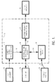
- Figure 1 is a functional block diagram of the HYDRA electrical system according to the present invention.
- Figure 2A is an abbreviated and partially cut away isometric view showing how the LED and photodetector mogation bar can be mounted within a piece of HYDRA office equipment.
- Figure 2B is an enlarged isometric view of the scanner input stage, including the LED and photodetector mogation bar and adjacent photoconductive drum, shown in Figure 2A.
- Figure 3A is an enlarged isometric view showing how the LED and photodetector mogation bar in Figures 2A and 2B above may be mounted between a pair of flexible end disk members for being driven back and forth in the direction of the arrows shown.
- Figure 3B is a cross sectional view taken along lines B-B of Figure 3A.
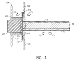
- Figure 4 is an enlarged cross sectional view showing one mounting arrangement suitable for electromagnetically driving the LED-photodetector mogation bar and mounted as shown on one of the circular flexible disk members in Figure 3A.
- the various electronic stages contained within the dotted line area 10 are those located within the main housing of the hybrid document processing or HYDRA equipment shown in the remaining figures of this specification. These various stages include a scanner 12 having a plurality of photodetectors therein to be described and which is operative to scan the contents of an adjacent passing input document 14. The scanner 12 is further operative to generate a scanned image output signal on line 16 which is then applied to a controller and mass storage memory stage 18.
- the controller and mass Storage memory stage 18 is connected to electrically interface with an external computer 20 via the two-way electrical interconnection 22 as shown and is further interconnected by another two way electrical interconnection 24 to a telephone modulator-demodulator (modem) unit 26.
- the telephone modem 26 may be connected in convention fashion via telephone lines 28 to a remote facsimile machine 30 in a well known manner.
- the controller and mass storage memory stage 18 has its electrical output connection 32 connected to an electrophotographic printing stage 34, such as a laser printer, which is operative to generate and print an output document indicated at 36 in Figure 1.
- the computer 20 is operative to generate an output command signal on its output line 22 and thereby direct the controller and mass storage memory stage 18 to either drive the electrophotographic printing stage 34 to directly print an output document 36 or to direct the scanner system 12 to scan a passing input document 14 and thereafter either store its contents in the memory stage 18 or directly print its contents in the electrophotographic printing stage 34.
- information received from the telephone lines 28 from a remote facsimile machine 30 may be converted by the telephone modem 26 to provide an input information signal on line 24 and applied to the controller and mass storage memory stage 18. This information is then stored in memory in stage 18 and subsequently made available on line 32 for application to the electrophotographic printing stage 34 where it may be printed as the output document 36.
- the HYDRA office equipment described and claimed herein includes a main housing 40 upon whose top surface is mounted a display panel 42.
- the input document and blank paper trays 44 and 46, respectively, are mechanically joined to the near end of the housing 40 and are operative to receive, respectively, a stack of printed input documents 48 and a stack of blank sheets of paper 50.
- Blank sheets from the paper source 50 are guided past the lower surface of the LED/photodetector mogation bar 52 and photoconductor 54 which is operative to receive "write" data from the LEDs of the mogation bar 52.
- the printed input documents from the stacked pages 48 are guided past the top surface of the LED/photodetector mogation bar 52 adjacent to a location thereon where the photodetectors are mounted.
- printed media on the downwardly facing surfaces of the printed documents 48 may be read by an array of photodetectors mounted on the upper surface of the mogation bar 52, and this scanned information is then passed either directly or indirectly to the light emitting diodes mounted on the other side of the mogation bar 52.
- LEDs are used to write the printed document information as a latent image onto the photoconductive drum 54 which is operative in a well known manner to transfer the latent image in a conventional fashion to a blank piece of paper 50 which then passes through the position indicated generally at the dotted line 56 and then into a first document collection output tray 58.
- the printed input document 48 passes through the dotted line position indicated generally at 60 and on into a second document collection output tray 62.
- each flexible end piece 64 may in turn be securely mounted to an adjacent wall or housing member 66, and an array photodetectors 68 are linearly arranged on the top surface of the mogation bar 52, whereas an array of light emitting diodes 70 are linearly arranged on the bottom surface of the mogation bar 52.
- the array of photodetectors 68 is operative to scan a printed input document at relatively high scan resolutions and scan speeds.
- the array of light emitting diodes 70 which is mounted on the bottom surface of the mogation bar 52 is operative to provide a write input data signal to the surface of the adjacent photoconductive drum member 54 from where a written latent image is transferred to a blank sheet of paper 50 using well known LED electophotographic printing processes.
- the writing of latent images on a photoconductive drum is well known in the art and is described, for example, in U.S. Patent application Serial No. 07/561,831 of Chris A. Storlie filed August 2, 1990, assigned to the present applicant and incorporated herein by reference.
- the LED-photodetector mogation bar 52 further includes top and bottom lens members 76 and 78 which are utilized for focusing the input and output image data to and from the arrays of photodetectors 68 and light emitting diodes 70, respectively.
- the LED-photodetector mogation bar 52 will typically include an elongated strip 80 on the top side of the bar 52 and containing the array of photodetectors 68 and a similar elongated strip 82 on the underside of the mogation bar 52 and containing the array 70 of light emitting diodes.
- the rib members 84 of each of the circular shaped disk support members 64 and 86 will flex and be driven in an oscillatory motion in the direction of the arrows 72 and 74 so as to enable the arrays of photodetectors 80 and light emitting diodes 82 to simultaneously mechanically and electrically scan and print documents in the manner described above.
- the photodetectors 68 on the top surface of the mogation bar 52 mechanically scan the printed documents in the path 60, but these photodetectors 68 may be electrically scanned as well in order to greatly enhance the resolution capability of the system.
- photodetectors 68 may be electrically scanned as well in order to greatly enhance the resolution capability of the system. For example, using prior art fixed position photodetectors and light emitting diodes, as many as three hundred to four hundred and fifty (300-450) photodetectors per linear inch of detector array was required if the sampling resolution needed in a given copying or scanning application is a corresponding three hundred to four hundred fifty dots per inch.
- this number of photodetectors per linear inch of photodetector array may be reduced by as much as 75% of the prior art requirement of three hundred photodetectors per linear inch, or reduced to a now-required 75 photodetectors per linear inch using the mogation scanning arrangement and technique described herein.
- the individual photodetector elements within the photodetector array may be positioned as indicated at region 90 within a central opening or cavity 92 located within the photodetector array housing strip 80.
- the individual photodetector elements 90 may then be covered with a suitable protective transparent lens material 94 as indicated.
- the individual light emitting diode elements may be positioned in a region 96 on the lower surface of the mogation bar 52 and there covered with a protective transparent lens material 98 as indicated and positioned in the central opening or cavity 100 in the LED housing strip 82.
- the above described transverse mogation or oscillation of the LED-photodetector mogation bar 52 may be accomplished by the use of an electromagnetic drive arrangement consisting of an electromagnet 102 which is securely attached to one side of a flexible circular ribbed disk member 104 at one end of the mogation bar 52.
- the flexible disk member 102 is further secured as shown to the ends 106 and 108 of an adjacent support housing, and the opening 110 in the support housing 106 and 108 allows the disk member 104 to freely move laterally back and forth in the direction of the arrows 112 and 114 and between the dotted line disk positions indicated at 116 and 118.
- the electromagnet 102 is surrounded by an oscillation drive coil 120 which is connected to receive an oscillation or mogation drive signal from an external source (not shown).
- the drive coil 120 is in turn mounted in an adjacent opening 122 of another housing member 124, and the electromagnet 102 is operative to move within the interior opening defined by the inner radius of the drive coil 120 and produce the transverse mogation and oscillation of the LED-photodetector mogation bar 52 in the direction of arrows 72, 74, and 112, 114 as indicated in Figure 4.
- the mogation method described and claimed herein allows one to obtain an analog representation of a scanned image and to simultaneously produce an image with a variable resolution.
- This variable resolution is dependent upon the sample rate, and by using both mechanical and electrical scanning it is possible to obtain a continuous pictorial of each surface area scanned. This is to be contrasted to a fixed array of photodetectors, for example, where it is not possible to "see” all of the areas of scanned image.
- the required number of photodetectors and LEDs is reduced, thereby significantly reducing the weight, size, cost and heat dissipation requirements (including large heat sinks) of the system while simultaneously enhancing its reliability and resolution capability.
- the present invention has the additional potential of eliminating the requirement for using gray scale image conversion techniques as a result of its enhanced resolution capabilities. Moreover, by properly controlling the scan rates in the X and Y directions, it is possible to achieve excellent scan resolutions in both the X and Y directions.
- All of this scan information may be used for high resolution applications, or alternatively, only a fraction of this information may be needed in low resolution facsimile and other similar office copying applications. Thus, in these latter low resolution applications, high speed operation may be achieved at relatively low power and heat dissipation levels. Where only low resolution draft copies are required, the page per minute throughput can be greatly increased by simply reducing the dots per minute printed.
- the abbreviated schematic mechanical mounting arrangement of the mogation bar 52, together with it associated photodetectors and light emitting diodes and the photoconductive drum 54 is intended to illustrate only a general location in which this scanning arrangement may be located in a piece of HYDRA office equipment 40 having multiple paper and document paths 56 and 60 as shown therein.
- the present invention is not limited to the use of any particular scanning electronics which may be connected into both the photodetector array and the light emitting diode array by those skilled in the image printing and conversion arts and using known document scanning and light emitting diode writing and electrophotographic printing techniques.
Landscapes
- Engineering & Computer Science (AREA)
- Multimedia (AREA)
- Signal Processing (AREA)
- Physics & Mathematics (AREA)
- General Physics & Mathematics (AREA)
- Printers Or Recording Devices Using Electromagnetic And Radiation Means (AREA)
- Exposure Or Original Feeding In Electrophotography (AREA)
- Facsimile Scanning Arrangements (AREA)
Applications Claiming Priority (2)
| Application Number | Priority Date | Filing Date | Title |
|---|---|---|---|
| US64121291A | 1991-01-15 | 1991-01-15 | |
| US641212 | 1996-04-30 |
Publications (2)
| Publication Number | Publication Date |
|---|---|
| EP0495433A2 true EP0495433A2 (de) | 1992-07-22 |
| EP0495433A3 EP0495433A3 (en) | 1993-04-14 |
Family
ID=24571416
Family Applications (1)
| Application Number | Title | Priority Date | Filing Date |
|---|---|---|---|
| EP19920100453 Withdrawn EP0495433A3 (en) | 1991-01-15 | 1992-01-13 | Combined printer, copier, scanner, and facsimile apparatus and method of operation |
Country Status (2)
| Country | Link |
|---|---|
| EP (1) | EP0495433A3 (de) |
| JP (1) | JPH0514636A (de) |
Cited By (5)
| Publication number | Priority date | Publication date | Assignee | Title |
|---|---|---|---|---|
| EP0630145A1 (de) * | 1993-06-14 | 1994-12-21 | Ricoh Company, Ltd | Digitale Kopiersysteme |
| EP0647056A1 (de) * | 1993-10-01 | 1995-04-05 | Canon Kabushiki Kaisha | Bildaufzeichnungsgerät |
| US5844687A (en) * | 1994-12-28 | 1998-12-01 | Canon Kabushiki Kaisha | Image processing apparatus |
| GB2380083A (en) * | 2001-09-25 | 2003-03-26 | Vidhya Rajeswar Thillainayagam | Combined scanner and printer. |
| US7872775B2 (en) | 2002-05-24 | 2011-01-18 | Lexmark International, Inc. | Apparatus and method for a resolution quality redefinition control system for a multi-function device |
Family Cites Families (7)
| Publication number | Priority date | Publication date | Assignee | Title |
|---|---|---|---|---|
| BR8102204A (pt) * | 1980-04-14 | 1981-11-24 | Xerox Corp | Aparelho grafico, e aparelho para oscilar axialmente um membro de sustentacao |
| US4424523A (en) * | 1982-07-02 | 1984-01-03 | Xerox Corporation | Read/write bar for multi-mode reproduction machine |
| JPS5983462A (ja) * | 1982-11-04 | 1984-05-14 | Fuji Xerox Co Ltd | 読取印字複写装置 |
| US4477175A (en) * | 1982-12-20 | 1984-10-16 | Xerox Corporation | Multi-function reproduction machine |
| JPS62140859A (ja) * | 1985-12-16 | 1987-06-24 | Brother Ind Ltd | 感光体記録装置 |
| US4821107A (en) * | 1987-01-26 | 1989-04-11 | Minolta Camera Kabushiki Kaisha | Multi-functional imaging apparatus |
| US5025321A (en) * | 1990-05-22 | 1991-06-18 | Westinghouse Electric Corp. | Facsimile machine using thin film electroluminescent device |
-
1992
- 1992-01-13 EP EP19920100453 patent/EP0495433A3/en not_active Withdrawn
- 1992-01-14 JP JP4024821A patent/JPH0514636A/ja active Pending
Cited By (8)
| Publication number | Priority date | Publication date | Assignee | Title |
|---|---|---|---|---|
| EP0630145A1 (de) * | 1993-06-14 | 1994-12-21 | Ricoh Company, Ltd | Digitale Kopiersysteme |
| US5506657A (en) * | 1993-06-14 | 1996-04-09 | Ricoh Company, Ltd. | Interleaving digital copier system |
| EP0647056A1 (de) * | 1993-10-01 | 1995-04-05 | Canon Kabushiki Kaisha | Bildaufzeichnungsgerät |
| US5832190A (en) * | 1993-10-01 | 1998-11-03 | Canon Kabushiki Kaisha | Image recording apparatus with reliable, efficient and power-saving stand-by state |
| US5844687A (en) * | 1994-12-28 | 1998-12-01 | Canon Kabushiki Kaisha | Image processing apparatus |
| GB2380083A (en) * | 2001-09-25 | 2003-03-26 | Vidhya Rajeswar Thillainayagam | Combined scanner and printer. |
| GB2380083B (en) * | 2001-09-25 | 2006-02-15 | Vidhya Rajeswar Thillainayagam | Scanner-printer |
| US7872775B2 (en) | 2002-05-24 | 2011-01-18 | Lexmark International, Inc. | Apparatus and method for a resolution quality redefinition control system for a multi-function device |
Also Published As
| Publication number | Publication date |
|---|---|
| JPH0514636A (ja) | 1993-01-22 |
| EP0495433A3 (en) | 1993-04-14 |
Similar Documents
| Publication | Publication Date | Title |
|---|---|---|
| EP0465216B1 (de) | Kompakter Lese-/Druck-Abtaster | |
| US4314282A (en) | Multifunction graphic engine based on an oscillating scanner | |
| US5796496A (en) | Image-data processing apparatus which automatically selects one of a copying function and a facsimile function based on an orientation of an original | |
| US6326993B1 (en) | Pulse width modulation system and image forming apparatus having the pulse width modulation system | |
| US5049999A (en) | Compact multimode input and output scanner | |
| US4893194A (en) | Multi-copy system for a digital copier | |
| JPS59119375A (ja) | 複数モ−ド複写機 | |
| EP0495433A2 (de) | Kombiniertes Druck-, Kopier-, Abtast- und Faksimilegerät und Verfahren zum Betrieb | |
| EP0465209A2 (de) | Abtaster mit Mitteln zur Registrierung von Vorlagen und Kopieblättern | |
| US5461413A (en) | Laser array printing | |
| US4926200A (en) | Electrophotographic printer | |
| US5921537A (en) | Post-processing apparatus of digital image forming apparatus | |
| EP0758177A2 (de) | Dünnfilmelektrolumineszenzvorrichtung zum Gebrauch in einem Faxgerät | |
| US4327990A (en) | Electronic printing apparatus | |
| JP3322737B2 (ja) | 画像形成装置 | |
| EP0039170A2 (de) | Kopierapparat | |
| US5506694A (en) | Scanner-equipped electrophotographic printing machine | |
| JP3441554B2 (ja) | 2色画像形成装置 | |
| EP0349628B1 (de) | Elektro-optisches aufzeichnungsgerät mit aufzeichnung gemäss mehreren auflösungen | |
| US6795100B1 (en) | Method and apparatus for controlling a light signal in electrophotographic developing type printer | |
| US5519498A (en) | Image forming apparatus | |
| JPH0251187B2 (de) | ||
| EP0562468A1 (de) | Bilderzeugungsgerät mit Kopierschutz | |
| JP3441666B2 (ja) | 画像形成装置 | |
| KR19980077261A (ko) | 잉크젯 복사기 |
Legal Events
| Date | Code | Title | Description |
|---|---|---|---|
| PUAI | Public reference made under article 153(3) epc to a published international application that has entered the european phase |
Free format text: ORIGINAL CODE: 0009012 |
|
| AK | Designated contracting states |
Kind code of ref document: A2 Designated state(s): DE FR GB IT |
|
| PUAL | Search report despatched |
Free format text: ORIGINAL CODE: 0009013 |
|
| AK | Designated contracting states |
Kind code of ref document: A3 Designated state(s): DE FR GB IT |
|
| 17P | Request for examination filed |
Effective date: 19931007 |
|
| 17Q | First examination report despatched |
Effective date: 19950131 |
|
| STAA | Information on the status of an ep patent application or granted ep patent |
Free format text: STATUS: THE APPLICATION IS DEEMED TO BE WITHDRAWN |
|
| 18D | Application deemed to be withdrawn |
Effective date: 19950613 |