EP0495491A2 - Calotte pour une tête d'enregistrement à jet d'encre - Google Patents
Calotte pour une tête d'enregistrement à jet d'encre Download PDFInfo
- Publication number
- EP0495491A2 EP0495491A2 EP92100656A EP92100656A EP0495491A2 EP 0495491 A2 EP0495491 A2 EP 0495491A2 EP 92100656 A EP92100656 A EP 92100656A EP 92100656 A EP92100656 A EP 92100656A EP 0495491 A2 EP0495491 A2 EP 0495491A2
- Authority
- EP
- European Patent Office
- Prior art keywords
- recording head
- ink
- ink jet
- cap
- jet recording
- Prior art date
- Legal status (The legal status is an assumption and is not a legal conclusion. Google has not performed a legal analysis and makes no representation as to the accuracy of the status listed.)
- Granted
Links
Images







Classifications
-
- B—PERFORMING OPERATIONS; TRANSPORTING
- B41—PRINTING; LINING MACHINES; TYPEWRITERS; STAMPS
- B41J—TYPEWRITERS; SELECTIVE PRINTING MECHANISMS, i.e. MECHANISMS PRINTING OTHERWISE THAN FROM A FORME; CORRECTION OF TYPOGRAPHICAL ERRORS
- B41J2/00—Typewriters or selective printing mechanisms characterised by the printing or marking process for which they are designed
- B41J2/005—Typewriters or selective printing mechanisms characterised by the printing or marking process for which they are designed characterised by bringing liquid or particles selectively into contact with a printing material
- B41J2/01—Ink jet
- B41J2/17—Ink jet characterised by ink handling
- B41J2/175—Ink supply systems ; Circuit parts therefor
- B41J2/17503—Ink cartridges
- B41J2/17553—Outer structure
-
- B—PERFORMING OPERATIONS; TRANSPORTING
- B41—PRINTING; LINING MACHINES; TYPEWRITERS; STAMPS
- B41J—TYPEWRITERS; SELECTIVE PRINTING MECHANISMS, i.e. MECHANISMS PRINTING OTHERWISE THAN FROM A FORME; CORRECTION OF TYPOGRAPHICAL ERRORS
- B41J2/00—Typewriters or selective printing mechanisms characterised by the printing or marking process for which they are designed
- B41J2/005—Typewriters or selective printing mechanisms characterised by the printing or marking process for which they are designed characterised by bringing liquid or particles selectively into contact with a printing material
- B41J2/01—Ink jet
- B41J2/135—Nozzles
- B41J2/165—Prevention or detection of nozzle clogging, e.g. cleaning, capping or moistening for nozzles
- B41J2/16505—Caps, spittoons or covers for cleaning or preventing drying out
- B41J2/16508—Caps, spittoons or covers for cleaning or preventing drying out connected with the printer frame
-
- B—PERFORMING OPERATIONS; TRANSPORTING
- B41—PRINTING; LINING MACHINES; TYPEWRITERS; STAMPS
- B41J—TYPEWRITERS; SELECTIVE PRINTING MECHANISMS, i.e. MECHANISMS PRINTING OTHERWISE THAN FROM A FORME; CORRECTION OF TYPOGRAPHICAL ERRORS
- B41J2/00—Typewriters or selective printing mechanisms characterised by the printing or marking process for which they are designed
- B41J2/005—Typewriters or selective printing mechanisms characterised by the printing or marking process for which they are designed characterised by bringing liquid or particles selectively into contact with a printing material
- B41J2/01—Ink jet
- B41J2/17—Ink jet characterised by ink handling
- B41J2/175—Ink supply systems ; Circuit parts therefor
- B41J2/17503—Ink cartridges
- B41J2/17533—Storage or packaging of ink cartridges
-
- B—PERFORMING OPERATIONS; TRANSPORTING
- B41—PRINTING; LINING MACHINES; TYPEWRITERS; STAMPS
- B41J—TYPEWRITERS; SELECTIVE PRINTING MECHANISMS, i.e. MECHANISMS PRINTING OTHERWISE THAN FROM A FORME; CORRECTION OF TYPOGRAPHICAL ERRORS
- B41J2/00—Typewriters or selective printing mechanisms characterised by the printing or marking process for which they are designed
- B41J2/005—Typewriters or selective printing mechanisms characterised by the printing or marking process for which they are designed characterised by bringing liquid or particles selectively into contact with a printing material
- B41J2/01—Ink jet
- B41J2/17—Ink jet characterised by ink handling
- B41J2/175—Ink supply systems ; Circuit parts therefor
- B41J2/17503—Ink cartridges
- B41J2/17536—Protection of cartridges or parts thereof, e.g. tape
Definitions
- the present invention relates to a cap for a recording head used for sealing tightly an ink ejection orifice of an ink jet recording head so as to protect the orifice, and an ink jet recording head in which the cap for a recording head can be mounted.
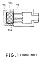
- a cap 70 covers the whole surface on which orifices 71a of the recording head 71 are arranged so that a swelling material inside the cap 70 absorbs ink fluid from the orifices 71a and swells so as to seal the orifices 71a.
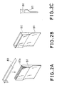
- Figs 2A, 2B and 2C also show a structure where a seal 80 is bonded on the surface on which orifices 81a of the recording head 81 are arranged so that the orifices 81a are sealed.
- the seal 90c which is larger than the orifice disposed face 91a is bonded onto the orifice disposed face 91a by using bonding materials with relatively weaker adhesive property.
- the bonded seal 90c is pressed by the pressing member 90b with a designated amount of force developed on the face around the orifices 91e on the orifice disposed face 91a.
- a pressing force developed by the pressing member 90b is applied by means that a couple of arms of the cap 90a is caught by a part of the recording head 91 when the cap 90a is installed in the recording head 91.
- Bonding materials used for contacting the seal 90c and the orifice disposed face 91a have a weak adhesive property as described above. That is, there is no need to guarantee complete sealing of the orifices by bonding the seal 90c itself, and hence, the seal 90c may have an adequate adhesive property so as to establish contacting of the seal 90c on the orifice disposed face. So far, it will be appreciated that the amount of bonding materials can be limited to be small enough to establish contacting of the seal 90c on the orifice disposed face and that unfavorable penetration of excess bonding materials into the orifices can be avoided so that bonding materials may not give unfavorable effect on ink ejection operations.
- the distribution of pressing force developed by the pressing member is not uniform over the concave shape because the shape of the contacting face of the pressing member 90b is a flat plane. That is, there may be a case that pressing member 90b cannot be deformed in responsive to the curved shape of the orifice disposed face and that, as a result, a well-conditioned contact between the seal 90c and the orifices 91e cannot be established.
- the pressing member 90b is composed of elastic and porous materials such as silicon porous materials and polyurethane porous materials which have a thickness of about three millimeters.
- the pressing member 90b has about 50 cells of air voids per 1 inch, seven to eight orifices may be defined in the corresponding cell. These orifices contacting cells of air voids are not pressed directly by the substantial pressing member 90b through the seal 90c, and these orifices are pressed only by the seal 90c.
- unfavorable phenomena such as an increase in the viscosity of ink fluid absorbed in the pressing member 90b and spilt ink fluid around the orifices.
- An object of the present invention is to provide a cap for a recording head which can seal tightly an ink ejection orifice and its neighboring part of the ink jet recording head, and an ink jet recording head which can use the cap.
- a cap which can be installed in an ink jet recording head for sealing an ink ejection orifice of the ink jet recording head, comprises: a contacting member having an elastically deformable convex part, the convex part contacting a face at which the ink ejection orifice is disposed and sealing the ink ejection orifice; and a pressing means for pressing the convex part of the contacting member toward the face by means of the installation of the cap.
- a container for storing an ink jet recording head comprises: a contacting member having an elastically deformable convex part, the convex part contacting a face at which an ink ejection orifice of the ink jet recording head is disposed and sealing the ink ejection orifice; and a pressing means for pressing the convex part of the contacting member toward the face by means of storing the ink jet recording head.
- an ink jet recording head for ejecting ink, comprises: a cap for sealing an ink ejection orifice of the ink jet recording head, the cap installed in the ink jet recording head so as to be removable from the ink jet recording head, the cap comprising: a contacting member having an elastically deformable convex part, the convex part contacting a face at which the ink ejection orifice is disposed and sealing the ink ejection orifice; and a pressing means for pressing the convex part of the contacting member toward the face by means of the installation of the cap.
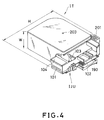
- Fig. 4 shows an example of an ink jet cartridge of one embodiment of the present invention which has a recording head and an ink tank within a single unit.
- the ink jet cartridge of this embodiment has an ink tank unit IT and a recording head unit IJU in a single body, which can be put on and taken off each other.
- a connector 102 for receiving signals for driving an ink ejection part 101 of the recording head unit IJU and for transmitting signals for reporting the residual amount of ink fluid to a recording apparatus control part is placed at the side face of the ink jet cartridge.
- the height of the ink jet cartridge mounted on a carriage to be described later can be taken to be small enough and the thickness of the ink jet cartridge can be taken to be small enough. So far, as shown in Fig. 13 later, it will be appreciated that in case of arranging a plurality of ink jet cartridges in one dimensional array, the carriage assembly can be taken to be small.
- the ink jet cartridge can be put on the carriage by carrying the ink jet cartridge with its handle 201 formed at the ink tank unit IT so that the ink ejection part 101 can face downward.
- the handle 201 is linked to a lever formed at the carriage to be described later which is used when installing the ink jet cartridge into the carriage.
- the head unit IJU can be positioned by way of a pin formed at the carriage being linked with a pin catcher part 103 formed at the head unit IJU.
- an absorber 104 used for cleaning a member wiping the surface of the ink ejection part 101 is placed beside the ink ejection part 101.
- an air duct port 203 used for introducing air as ink fluid consumption proceeds is placed almost at the center of the ink tank unit IT.
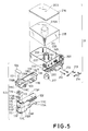
- Fig. 5 is an exploded perspective view of the ink jet cartridge shown in Fig. 4.
- the ink jet cartridge is composed of the recording head unit IJU and the ink tank unit IT. In the followings, the detailed structure of these units IJU and IT is described.
- a base plate 111 made of Al On the base plate 111, a substrate 112 on which formed are electronic devices generating thermal energy used for ejecting ink and a print circuit board (PCB) 115 containing electric circuitry for supplying electric power to these devices are mounted, and the substrate 112 and the PCB 115 are connected to each other through wire bonding wirings. On the substrate, installed are electro-thermal conversion elements generating thermal energy used for inducing film boiling in ink fluid in response to electric power supply to the elements. In the following description, the substrate 112 is designated a heater board.
- PCB 115 is formed as a two-sides circuit board on which mounted are condenser (not shown) and IC (not shown) made as a ROM device which contains data generic to the recording head such as adequate driving conditions for electro-thermal conversion elements, ID numbers, ink color attributes and supplementary data for driving conditions such as head shading (HS).
- condenser not shown
- IC not shown
- HS head shading
- an upper plate 113 On the heater board 112, disposed is an upper plate 113 having a concave part forming a common fluid reservoir storing temporarily ink fluid supplied from ink tank unit IT, and a plurality of fluid paths connecting the common fluid reservoir and ink ejection orifices perspectively.
- an orifice plate 113A at which an orifices are formed is integrally formed with the upper plate 113.
- a component 114 is a leaf spring for pressing tightly the upper plate 113 against the heater board 112 so that an ink ejection part 101 can be formed.
- a component 116 is a head unit cover which is formed in a mold containing an ink fluid supply tube part 116A entering into the ink tank unit IT, an ink fluid channel 116B between the ink fluid supply tube part 116A and an ink fluid leading tube part at the upper plate, three pins 116C for fixing the head unit cover on the base plate 111, a pin coupling part 103, a mounting part of an absorber 104 and the lest.
- an ink fluid route cover 117 is placed as for the ink fluid channel 116B.
- a filter 118 for removing small-sized air bubbles and dusts is placed at the top of the ink fluid supply tube part 116A and an O ring is also placed in order to prevent ink fluid leakage from connecting portions of the above mentioned components.
- a protruding pin 111P formed on the base plate is positioned by being inserted into a penetration hole 115P formed in PCB 115 and both of the protruding pin 111P and the penetration hole 115P are fixed with bonding and so on.
- precise positioning is not required. This is because fixing of the heater board 112 in responsive to the base plate 111 which requires high precision can be done independently with respect to PCB 115.
- the heater board 112 is fixed with higher precision on the base plate 111 and is connected electrically to PCB 115. And the upper plate 113 and the spring 114 are placed with adequate bonding and sealing, and three protruding pins 116C are fixed by being inserted through the hole 111C on the base plate 111. Finally, the head unit is completed by heating and pressing pins 116C.
- a component 211 is an ink fluid reservoir forming a body of the ink tank unit
- a component 215 is an ink fluid absorber
- a component 216 is an ink tank cover
- a component 212 is an electrode pin for detecting the amount of ink fluid in the ink fluid reservoir and components 213 and 214 are contacting members in responsive to the electrode pin 212.
- the ink fluid reservoir 211 has a member 220 used for mounting the pin 212, the contacting members 213 and 214, and used for mounting the above mentioned head unit IJU, a supply port 231 for accepting the ink supply tube part 116A, and a lever 201, as well as a hollow cylinder part 233 standing almost at the center of the bottom of the ink fluid reservoir as shown in Fig. 5.
- This ink fluid reservoir 211 can be formed by molding synthetic materials in a single body.
- the bottom side of the hollow cylinder 233 is opened in supplying ink fluid into the ink fluid reservoir 211 and after the ink fluid reservoir 211 is filled with ink fluid, the bottom side of the hollow cylinder 233 is closed with a cap 217 shown in Fig. 5.
- the inside space of the hollow cylinder 233 is used as a buffer part for preventing ink fluid leakage due to vibration and movement applied to the ink tank reservoir 211. And furthermore, as the spiral channel 233 makes the air route to the air duct port 203 longer, it will be appreciated that ink fluid leakage can be effectively prevented.
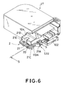
- Figs. 6 and 7 are perspective views of an ink jet cartridge shown in Figs. 4 and 5 with a cap of one embodiment of the present invention; Fig. 6 shows the case that the cap is installed, and Fig. 7 shows the case that the cap is removed.
- the cap 2 is made of synthetic materials and the cap 2 is composed of a holder 21 which is shaped in an open square and has an L-shaped arm at the center of the holder 21 and of a contacting member 20 supported by the holder 21.
- the cap 2 is installed on the ink fluid ejection part 101, the top part 21D of the L-shaped arm standing from the center of the cap 2 touches the upper face of the ink absorber 104 placed above the ink fluid ejection part 101.
- the relationship between the distance between the protruding parts 21B and 21F and the contacting member 20 and the distance between the orifice disposed face 113e to which the contacting member 20 contacts and the channels 16a and 16b is determined adequately. With this determination of distance relationship, when the protruding parts 21B and 21f are caught by the channels 16a and 16b, the orifice disposed face 113e is pressed by the contacting member 20 as described later.
- the cap 2 is removed from the ink fluid ejection part 101, the one holder beam of the holder 21 is displaced outside by pulling a handle portion 21A.
- the handle portion 21A may be bent at an angle of 45°-90° relative to the holder beam. So far, the cap 2 can be easily removed even if the cap 2 is securely fixed to the ink fluid ejection part 101.
- the cap 2 since the cap 2 can be removed from the ink fluid ejection part 101 only when the handle portion 21A is pulled, the cap can be protected from being dripped by a shock at transportation.
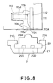
- Fig. 8 shows a case that the contacting member 20 of the cap 2 is put away from the orifice disposed face 113e.
- Fig. 9 shows a case that the contacting member 20 of the cap 2 touches the orifice disposed face 113e.
- Figs. 8 and 9 are magnified cross-sectional views of the cap 2 and the major part of the recording head unit, each view projected in the direction of the arrow S shown in Fig. 6.
- the contacting member 20 is supported by a latch 21G formed at the center side of the holder 21 and by two latches 21H formed at the other side of the holder 21.
- Materials used for the contacting member 20 are supposed to be elastic materials including rubbers such as nytril rubber, silicon rubber, fluorine rubber and urethane rubber, or thermal-plastic elastomers, the hardness of which is preferred to be less than or equal to 80° in JIS A and to maintain its own shape and not to be adhesive.
- the materials for the member 20 is preferred to be ink-resisting.
- the cross-sectional shape of the orifice disposed face 113e is unsymmetrical concave arc and this concave shape is extended upward and downward in a designated length in the vertical direction relative to the figure plane.
- the half-moon-shaped contacting part 20A of the contacting member 20 is extended upward and downward in an identical length to that of the orifice disposed face 113e in the vertical direction relative to the figure plane.
- the concave shape of the orifice disposed face 113e is determined in the following reasons.
- the orifice 113i is so fabricated by applying laser beams.
- the orifice disposed face 113e and its axis are tilted in relative to the fluid path.
- the distance between the orifice disposed face 113e so tilted and the recording medium is selected to be an adequate value and that the pressing force developed by the pressing spring 114 (shown in Fig.
- the unsymmetrical concave shape of the cross-section of the orifice disposed face 113e is determined by considering the direction in which the before mentioned blade wipes the orifice disposed face 113e and by considering the relative positions of the absorber 104 for cleaning this blade and the orifice disposed face 113e. So determined the cross-sectional shape of the orifice disposed face 113e, the efficiency of wiping the orifice disposed face 113e by the blade is attained to be high.
- the position of the contacting part 20A when contacting the orifice disposed face 113e is selected so that the top of the circle of the half-moon-shaped contacting part 20A may goes to the deepest point of the orifice disposed face 113e.
- the contacting part 20A contacts the deepest point of the orifice disposed face 113e, it will be appreciated that a pressing force can be prevented from being applied directly to a part where the orifice 113i which does not have an enough structural rigidity is placed. And furthermore, the pressing force is applied to the deepest point of the orifice disposed face 113e, a uniform pressing force can be established on the whole face of the orifice disposed face 113e. In the orifice disposed face 113e, the orifice 113i is shifted from this deepest point of the arc. Owing to this configuration, the efficiency of wiping the orifice disposed face 113e by the blade is attained to be high, too.
- the orifice 113i can be sealed tightly by means that the contacting part 20A is deformed by the force developed by the channels 16a and 16b on the side face of the ejection part 101 catching the above mentioned protruding parts 21B and 21F of the holder 21. That is, as the contacting part 20A has a half-moon-shaped cross-section, the press force can be developed almost uniformly against the orifice disposed face 113e. And hence, the contacting part 20A can be deformed almost uniformly in the concave shape in responsive to the concave shape of the orifice disposed face 113e. So far, the contacting part 20A can seal tightly the orifice 113i.
- a preferred shape of the contacting part 20A is also supposed to be a half-oval as well as a half-moon shape.
- the shape of the contacting part 20A is not limited to these shapes but may be selected to be optimal one in relative to the shape of the orifice disposed face 113e.
- its curvature radius is a little smaller than that of the concave shape part of the orifice disposed face.
- the amount of deformation of the contacting part 20A is about 0.5 mm, which is within a favorable range between 0.3 mm and 0.9 mm.
- the orifice 113i and its neighboring area can be sealed tightly with the contacting part composed of elastic and deformable materials, in sealing the orifice 113i, a uniform press force can be developed and the shape of the contacting part can be deformed to be an identical shape to the shape of the orifice disposed face 113e. As a result, the orifice 113i and its neighboring area can be sealed tightly.
- the channels 20D which are formed in the contacting member 20 and which extend along the array of the orifices 113i are so designed that the elastic deformation of the contacting member 20 may be adequate and that deformation of the contacting member 20 in its installation and easiness of installation may be considered.
- the shape of the orifice disposed face sealed tightly by the cap of the present invention is selected to be an unsymmetrical concave, it will be appreciated that, in case of using a flat-shaped orifice disposed face 113e, an effective sealing of the orifice disposed face can be attained. In this case, desirable and tight sealing of the orifice disposed face 113e or its neighboring area can be established by means that the top of the contacting part 20A is positioned to a designated position of the orifice 113i.
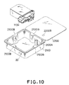
- Figs. 10 and 11 are a perspective view and a plan view showing a container storing the above mentioned ink jet cartridge as shown in Figs. 4 and 5, respectively.
- the ink jet cartridge is transported and stored within the container.
- the container of this embodiment is also used as a holder of the contacting member described in the above embodiment. That is, as shown in Figs. 10 and 11, the contacting member 20, which is formed similarly to that of the above mentioned embodiment shown in Figs. 8 and 9, is mounted within a part of the container 2100.
- the orifice disposed face 113e contacts the contacting member 20 and tight sealing of the orifice is established.
- a cylindrical-shaped protruding part 2100A is formed, which is used as a positioning member when the ink jet cartridge is installed and stored in the container 2100.
- this cylindrical-shaped protruding part 2100A functions in such manner that the orifice disposed face 113e of the ink jet cartridge installed in the container 2100 pushes the contacting member 20 because the distance between the contacting member 20 and the cylindrical-shaped protruding part 2100A is less than the length of the corresponding portion of the cartridge. So far, in installing the ink jet cartridge into the container 2100, tight sealing of the orifice disposed face 113e can be established.
- the protruding part 2100A is linked with the hole 2200B formed in the cover 2200 of the container when the cover 2200 is closed so that the cover 2200 is fixed with the container 2100.
- components 2100B are convex portions for positioning the ink jet cartridge installed within the container 2100.
- Fig. 12 is a plan view of the other embodiment of the above mentioned container.
- the container 2100 has an inner structure adjusted for the shape of the ink jet cartridge.
- the contacting member 20 for sealing the orifice disposed face is also formed.
- a component 2100B is a hole for fixing the cover, and a cylindrical-shaped protruding part to be linked with the hole 2100B is formed in the container cover, not shown in Fig. 11.
- Shapes of the contacting member and the orifice disposed face may not be limited to those described in the above embodiments. That is, the contacting member of the present invention can be elastically deformed in responsive to the shape of the orifice disposed face so that tight sealing of the orifice disposed face may be established.
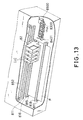
- Fig. 13 is a perspective view of an ink jet recording apparatus using the above mentioned ink jet cartridge.
- the ink jet recording apparatus of Fig. 13 is a full-color serial type printer which have exchangeable ink tanks, each of which corresponds to ink colors of black (Bk), cyan (C), magenta (M) and yellow (Y).
- Bk black
- C cyan
- M magenta
- Y yellow
- the ink jet head of this embodiment has 128 pieces of orifices and gives a recording density of 400 dots per inch with a driving frequency 4KHz for ejecting ink fluid periodically.
- components IJC are four ink jet cartridges, each cartridge corresponding to each individual ink color, yellow, magenta, cyan or black.
- the ink jet cartridge is formed in a unit containing a recording head unit, and an ink tank unit storing ink fluid to be supplied to the recording head unit.
- the ink jet cartridge IJC is mounted on the carriage so that the ink jet cartridge IJC may be removable for the carriage with a structure not shown in Fig. 13.
- the carriage 82 is supported on the guide rail 811 so that the carriage 82 can move along the guide rail 811, and the carriage 82 is connected to a part of a drive belt 852 driven by a main scan motor not shown in Fig. 13.
- the ink jet cartridge IJC can move along the guide rail 811.
- Components 815, 816, 817 and 818 are transport rollers placed to be parallel to the guide rail 811; transport rollers 815 and 816 are placed behind the guide rail 811, and transport rollers 817 and 818 are placed in front of the guide rail 811.
- Transport rollers 815, 816, 817 and 818 are driven by a sub scan motor in order to supply a recording medium P.
- the recording medium P is supplied forward to the orifice disposed face of the ink jet cartridge IJC so as to establish a recording face on the recording medium P.
- a component 8300 is a cap unit corresponding to each recording head of the ink jet cartridge IJC.
- the cap unit 8300 can move in the horizontal direction in Fig. 13, and move in relative to the movable region of the ink jet cartridge IJC.
- the carriage 82 is located at the home position, the cap unit 8300 moves forward to the recording head and contacts the recording head, and finally covers the orifice disposed face.
- a component 8401 is a blade used as a wiping member.
- a component 8500 is a pump unit evacuating ink fluid from the orifice of the recording head and its neighboring area through the cap unit 8300.
- a cap structure where a seal tape is not used between the contacting member of the cap and the orifice disposed face. It will be appreciated that the case that a seal tape is used in the cap of the present invention may give the similar advantage to that of the present invention.
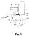
- Figs. 14 and 15 shows a case that a seal tape is used in a cap structure shown in Figs. 8 and 9.
- a seal tape 20c is shaped and bonded on the orifice disposed face 113e prior to installing cap 2 in the recording head.
- the pressing member 20A presses the seal 20c against the orifice disposed face. So far, in the cap structure of the present invention, the pressing force developed by the cap can be applied effectively and uniformly onto the seal 20c, and hence, the sealing of the orifice 113i by the seal 20c can be established effectively.
- the present invention achieves distinct effect when applied to a recording head or a recording apparatus which has means for generating thermal energy such as electrothermal transducers or laser light, and which causes changes in the ink by the thermal energy so as to eject ink. This is because such a system can achieve a high density and high resolution recording.
- the on-demand type apparatus has electrothermal transducers, each disposed on a sheet or liquid passage that retains liquid (ink), and operates as follows: first, one or more drive signals are applied to the electrothermal transducers to cause thermal energy corresponding to recording information; second, the thermal energy induces sudden temperature rise that exceeds the nucleate boiling so as to cause the film boiling on heating portions of the recording head; and third, bubbles are grown in the liquid (ink) corresponding to the drive signals. By using the growth and collapse of the bubbles, the ink is expelled from at least one of the ink ejection orifices of the head to form one or more ink drops.
- the drive signal in the form of a pulse is preferable because the growth and collapse of the bubbles can be achieved instantaneously and suitably by this form of drive signal.
- a drive signal in the form of a pulse those described in U.S. patent Nos. 4,463,359 and 4,345,262 are preferable.
- the rate of temperature rise of the heating portions described in U.S. patent No. 4,313,124 be adopted to achieve better recording.
- U.S. patent Nos. 4,558,333 and 4,459,600 disclose the following structure of a recording head, which is incorporated to the present invention: this structure includes heating portions disposed on bent portions in addition to a combination of the ejection orifices, liquid passages and the electrothermal transducers disclosed in the above patents. Moreover, the present invention can be applied to structures disclosed in Japanese Patent Application Laying-open Nos. 123670/1984 and 138461/1984 in order to achieve similar effects.
- the former discloses a structure in which a slit common to all the thermoelectric transducers is used as ejection orifices of the electrothermal transducers, and the latter discloses a structure in which openings for absorbing pressure waves caused by thermal energy are formed corresponding to the ejection orifices.
- the present invention can be also applied to a so-called full-line type recording head whose length equals the maximum length across a recording medium.
- a recording head may consists of a plurality of recording heads combined together, or one integrally arranged recording head.
- the present invention can be applied to various serial type recording heads: a recording head fixed to the main assembly of a recording apparatus; a conveniently replaceable chip type recording head which, when loaded on the main assembly of a recording apparatus, is electrically connected to the main assembly, and is supplied with ink therefrom; and a cartridge type recording head integrally including an ink reservoir.
- a recovery system or a preliminary auxiliary system for a recording head as a constituent of the recording apparatus because they serve to make the effect of the present invention more reliable.
- the recovery system are a capping means and a cleaning means for the recording head, and a pressure or suction means for the recording head.
- the preliminary auxiliary system are a preliminary heating means utilizing electrothermal transducers or a combination of other heater elements and the electrothermal transducers, and a means for carrying out preliminary ejection of ink independently of the ejection for recording. These systems are effective for reliable recording.
- the number and type of recording heads to be mounted on a recording apparatus can be also changed. For example, only one recording head corresponding to a single color ink, or a plurality of recording heads corresponding to a plurality of inks different in color or concentration can be used.
- the present invention can be effectively applied to an apparatus having at least one of the monochromatic, multi-color and full-color modes.
- the monochromatic mode performs recording by using only one major color such as black.
- the multi-color mode carries out recording by using different color inks, and the full-color mode performs recording by color mixing.
- inks that are liquid when the recording signal is applied can be used: for example, inks can be employed that solidify at a temperature lower than the room temperature and are softened or liquefied in the room temperature. This is because in the ink jet system, the ink is generally temperature adjusted in a range of 30°C - 70°C so that the viscosity of the ink is maintained at such a value that the ink can be ejected reliably.
- the present invention can be applied to such apparatus where the ink is liquefied just before the ejection by the thermal energy as follows so that the ink is expelled from the orifices in the liquid state, and then begins to solidify on hitting the recording medium, thereby preventing the ink evaporation: the ink is transformed from solid to liquid state by positively utilizing the thermal energy which would otherwise cause the temperature rise; or the ink, which is dry when left in air, is liquefied in response to the thermal energy of the recording signal.
- the ink may be retained in recesses or through holes formed in a porous sheet as liquid or solid substances so that the ink faces the electrothermal transducers as described in Japanese Patent Application Laying-open Nos. 56847/1979 or 71260/1985.
- the present invention is most effective when it uses the film boiling phenomenon to expel the ink.
- the ink jet recording apparatus of the present invention can be employed not only as an image output terminal of an information processing device such as a computer, but also as an output device of a copying machine including a reader, as an output device of a facsimile apparatus having a transmission and receiving function, and as an output device of an optical disc apparatus for recording and/or reproducing information into and/or from an optical disc.
- an information processing device such as a computer
- an output device of a copying machine including a reader as an output device of a facsimile apparatus having a transmission and receiving function
- an optical disc apparatus for recording and/or reproducing information into and/or from an optical disc.
- Fig. 16 schematically illustrates one embodiment of a utilizing apparatus in accordance with the present invention to which the ink jet recording system shown in Fig. 13 is equipped as an output means for outputting processed information.
- reference numeral 10000 schematically denotes a utilizing apparatus which can be a work station, a personal or host computer, a word processor, a copying machine, a facsimile machine or an optical disc apparatus.
- Reference numeral 11000 denotes the ink jet recording apparatus (IJRA) shown in Fig. 13.
- the ink jet recording apparatus (IJRA) 11000 receives processed information form the utilizing apparatus 10000 and provides a print output as hand copy under the control of the utilizing apparatus 10000.
- Fig. 17 schematically illustrates another embodiment of a portable printer in accordance with the present invention to which a utilizing apparatus such as a work station, a personal or host computer, a word processor, a copying machine, a facsimile machine or an optical disc apparatus can be coupled.
- a utilizing apparatus such as a work station, a personal or host computer, a word processor, a copying machine, a facsimile machine or an optical disc apparatus can be coupled.
- reference numeral 10001 schematically denotes such a utilizing apparatus.
- Reference numeral 12000 schematically denotes a portable printer having the ink jet recording apparatus (IJRA) 11000 shown in Fig. 13 is incorporated thereinto and interface circuits 13000 and 14000 receiving information processed by the utilizing apparatus 11001 and various controlling data for controlling the ink jet recording apparatus 11000, including hand shake and interruption control from the utilizing apparatus 11001. Such control per se is realized by conventional printer control technology.
- IJRA ink jet recording apparatus
- a cap (2) installed in an ink jet recording head (IJU) for sealing an ink ejection orifice (113i) of the ink jet recording head (IJU) comprises a contacting member (20) and a pressing structure (2, 21B, 21F, 16a, 16b).
- the contacting member (20) is a member having an elastically deformable convex part (20A) which contacts a face (113e) on which the orifice (113i) is disposed and seals the orifice (113i).
- the pressing structure (2, 21B, 21F, 16a, 16b) presses the convex part (20A) of the contacting member (20) toward the face (113e) in responsive to installing the cap (2).
Landscapes
- Ink Jet (AREA)
- Facsimile Heads (AREA)
Applications Claiming Priority (2)
| Application Number | Priority Date | Filing Date | Title |
|---|---|---|---|
| JP4707/91 | 1991-01-18 | ||
| JP3004707A JPH04247954A (ja) | 1991-01-18 | 1991-01-18 | インクジェット記録ヘッド用キャップ,インクジェット記録ヘッド,およびインクジェット記録装置 |
Publications (3)
| Publication Number | Publication Date |
|---|---|
| EP0495491A2 true EP0495491A2 (fr) | 1992-07-22 |
| EP0495491A3 EP0495491A3 (en) | 1993-01-20 |
| EP0495491B1 EP0495491B1 (fr) | 1999-04-21 |
Family
ID=11591357
Family Applications (1)
| Application Number | Title | Priority Date | Filing Date |
|---|---|---|---|
| EP92100656A Expired - Lifetime EP0495491B1 (fr) | 1991-01-18 | 1992-01-16 | Calotte pour une tête d'enregistrement à jet d'encre |
Country Status (6)
| Country | Link |
|---|---|
| US (1) | US5648802A (fr) |
| EP (1) | EP0495491B1 (fr) |
| JP (1) | JPH04247954A (fr) |
| AT (1) | ATE179121T1 (fr) |
| DE (1) | DE69228958T2 (fr) |
| ES (1) | ES2130141T3 (fr) |
Cited By (9)
| Publication number | Priority date | Publication date | Assignee | Title |
|---|---|---|---|---|
| EP0603515A1 (fr) * | 1992-12-22 | 1994-06-29 | Hewlett-Packard Company | Structure d'un dispositif d'écriture étroit pour une imprimante à jet d'encre thermique |
| EP0603516A3 (en) * | 1992-12-22 | 1994-09-21 | Hewlett Packard Co | Ink cartridge with ink reservoir and printhead. |
| EP0622196A3 (fr) * | 1993-04-30 | 1995-01-25 | Hewlett Packard Co | Bande à fentes pour buses pour tête d'impression par jet d'encre. |
| DE4326564A1 (de) * | 1993-08-07 | 1995-02-09 | Inkjet Systems Gmbh Co Kg | Düsenabdeckung für einen Tintendruckkopf und Verfahren zum Aufbringen derselben |
| EP0671273A1 (fr) * | 1994-03-10 | 1995-09-13 | Hewlett-Packard Company | Capuchon protecteur pour un dispositif d'écriture par jet d'encre |
| EP0900661A3 (fr) * | 1997-09-03 | 1999-07-28 | Hewlett-Packard Company | Récipient de stockage pour cartouches à jet d'encre équipé d'un moyen de nettoyage et procédé de stockage de cartouches à jet d'encre |
| US6036305A (en) * | 1994-12-28 | 2000-03-14 | Fujitsu, Limited | Ink cartridge with residual ink retaining structure |
| US6142602A (en) * | 1997-03-27 | 2000-11-07 | Nec Corporation | Ink cartridge and ink jet recording apparatus |
| CN1330495C (zh) * | 2004-01-08 | 2007-08-08 | 索尼株式会社 | 喷嘴帽、头帽单元以及液体喷射头 |
Families Citing this family (19)
| Publication number | Priority date | Publication date | Assignee | Title |
|---|---|---|---|---|
| US5424768A (en) * | 1993-06-21 | 1995-06-13 | Xerox Corporation | Zero-volume maintenance cap for an ink jet printhead |
| JP3188056B2 (ja) * | 1993-07-21 | 2001-07-16 | キヤノン株式会社 | インクジェット記録装置およびインクジェットヘッド |
| US5784086A (en) * | 1995-03-22 | 1998-07-21 | Mitsubishi Pencil Corporation Of America | Ink cartridge holding box for refilling |
| DE69733980T2 (de) * | 1996-06-07 | 2006-02-23 | Canon K.K. | Verfahren und Vorrichtung zum Ausstossen von Flüssigkeit |
| JP4022946B2 (ja) * | 1996-11-15 | 2007-12-19 | ブラザー工業株式会社 | キャッピング装置 |
| JP3768633B2 (ja) * | 1997-02-14 | 2006-04-19 | キヤノン株式会社 | インクジェットカートリッジおよびプリント装置 |
| US6199973B1 (en) * | 1997-09-03 | 2001-03-13 | Hewlett Packard Company | Storage container for inkjet cartridges having removable capping means and a method for storing inkjet cartridges |
| JPH11320897A (ja) | 1998-03-11 | 1999-11-24 | Canon Inc | 記録ヘッド用キャップ、該キャップを装着可能な記録ヘッド、記録ヘッドへのキャップの取付け方法及び取付け装置 |
| US6588875B1 (en) | 2001-12-04 | 2003-07-08 | John W. Kleinhammer | Ink jet cartridge printhead seal |
| US6540323B1 (en) * | 2002-01-31 | 2003-04-01 | Hewlett-Packard Development Company, L.P. | Snout-encompassing capping system for inkjet printheads |
| US6769761B2 (en) | 2002-08-29 | 2004-08-03 | Hewlett-Packard Development Company, L.P. | Inkjet printer having ink cartridge tape removal capability and method of assembling the printer |
| TWI245712B (en) * | 2004-05-05 | 2005-12-21 | Benq Corp | Cap and office machine utilizing the same |
| US20060012628A1 (en) * | 2004-07-13 | 2006-01-19 | Nu-Kote International, Inc. | Transportation pad for ink cartridge |
| JP4715169B2 (ja) * | 2004-11-18 | 2011-07-06 | ブラザー工業株式会社 | インクカートリッジのための保護部材 |
| US7461930B2 (en) * | 2005-03-17 | 2008-12-09 | Lexmark International, Inc. | Seal for inkjet orifices |
| DE102009011097A1 (de) * | 2009-03-03 | 2010-09-09 | Bowa Bosse + Wagner Ohg | Vorrichtung zur Aufbewahrung einer Patrone für Tintenstrahldrucker |
| JP5728940B2 (ja) * | 2010-12-28 | 2015-06-03 | セイコーエプソン株式会社 | 液体噴射装置 |
| JP6095542B2 (ja) * | 2013-09-27 | 2017-03-15 | 富士フイルム株式会社 | 液滴吐出装置 |
| JP2021069993A (ja) * | 2019-10-31 | 2021-05-06 | キヤノン株式会社 | ウルトラファインバブル生成装置およびその制御方法 |
Family Cites Families (23)
| Publication number | Priority date | Publication date | Assignee | Title |
|---|---|---|---|---|
| CA1127227A (fr) * | 1977-10-03 | 1982-07-06 | Ichiro Endo | Procede d'enregistrement a jet liquide et appareil d'enregistrement |
| JPS5936879B2 (ja) * | 1977-10-14 | 1984-09-06 | キヤノン株式会社 | 熱転写記録用媒体 |
| US4330787A (en) * | 1978-10-31 | 1982-05-18 | Canon Kabushiki Kaisha | Liquid jet recording device |
| US4345262A (en) * | 1979-02-19 | 1982-08-17 | Canon Kabushiki Kaisha | Ink jet recording method |
| US4463359A (en) * | 1979-04-02 | 1984-07-31 | Canon Kabushiki Kaisha | Droplet generating method and apparatus thereof |
| US4313124A (en) * | 1979-05-18 | 1982-01-26 | Canon Kabushiki Kaisha | Liquid jet recording process and liquid jet recording head |
| US4558333A (en) * | 1981-07-09 | 1985-12-10 | Canon Kabushiki Kaisha | Liquid jet recording head |
| JPS5914962A (ja) * | 1982-07-15 | 1984-01-25 | Seiko Epson Corp | インクジェットプリンタ |
| JPS59123670A (ja) * | 1982-12-28 | 1984-07-17 | Canon Inc | インクジエツトヘツド |
| JPS59138461A (ja) * | 1983-01-28 | 1984-08-08 | Canon Inc | 液体噴射記録装置 |
| JPS6071260A (ja) * | 1983-09-28 | 1985-04-23 | Erumu:Kk | 記録装置 |
| JPS60162655A (ja) * | 1984-02-03 | 1985-08-24 | Nec Corp | インクジエツトプリンタ |
| JPS60204348A (ja) * | 1984-03-30 | 1985-10-15 | Canon Inc | 液体噴射記録ヘツドの保護部材 |
| JPS6137436A (ja) * | 1984-07-31 | 1986-02-22 | Canon Inc | 記録ヘツドカバ− |
| JPS61125851A (ja) * | 1984-11-22 | 1986-06-13 | Canon Inc | インクジエツト記録装置 |
| JPS6219460A (ja) * | 1985-07-19 | 1987-01-28 | Ricoh Co Ltd | インクカ−トリツジの梱包容器 |
| JPS6312149A (ja) * | 1986-07-02 | 1988-01-19 | Mitsubishi Electric Corp | 半導体装置の製造方法 |
| JP2626805B2 (ja) * | 1987-10-30 | 1997-07-02 | キヤノン株式会社 | インクジェット記録装置 |
| AU635562B2 (en) * | 1989-09-18 | 1993-03-25 | Canon Kabushiki Kaisha | Recording head with cover |
| JP2683120B2 (ja) * | 1989-12-06 | 1997-11-26 | キヤノン株式会社 | インクジエツトカートリツジの収納容器 |
| US5131539A (en) * | 1989-12-06 | 1992-07-21 | Canon Kabushiki Kaisha | Package for ink jet cartridge |
| DE3940316A1 (de) * | 1989-12-06 | 1991-06-13 | Bollig & Kemper | Waessrige dispersionen von vernetzten polymermikroteilchen |
| EP0435666B1 (fr) * | 1989-12-29 | 1996-04-03 | Canon Kabushiki Kaisha | Dispositif de récupération par aspiration et appareil d'enregistrement à jet d'encre comportant le dispositif |
-
1991
- 1991-01-18 JP JP3004707A patent/JPH04247954A/ja active Pending
-
1992
- 1992-01-16 DE DE69228958T patent/DE69228958T2/de not_active Expired - Fee Related
- 1992-01-16 ES ES92100656T patent/ES2130141T3/es not_active Expired - Lifetime
- 1992-01-16 EP EP92100656A patent/EP0495491B1/fr not_active Expired - Lifetime
- 1992-01-16 AT AT92100656T patent/ATE179121T1/de not_active IP Right Cessation
-
1995
- 1995-02-23 US US08/393,251 patent/US5648802A/en not_active Expired - Fee Related
Cited By (14)
| Publication number | Priority date | Publication date | Assignee | Title |
|---|---|---|---|---|
| EP0603516A3 (en) * | 1992-12-22 | 1994-09-21 | Hewlett Packard Co | Ink cartridge with ink reservoir and printhead. |
| US5870125A (en) * | 1992-12-22 | 1999-02-09 | Hewlett-Packard Company | Thin pen structure for thermal ink-jet printer |
| US5491502A (en) * | 1992-12-22 | 1996-02-13 | Hewlett-Packard Company | Thin pen structure for thermal ink-jet printer |
| EP0603515A1 (fr) * | 1992-12-22 | 1994-06-29 | Hewlett-Packard Company | Structure d'un dispositif d'écriture étroit pour une imprimante à jet d'encre thermique |
| EP0622196A3 (fr) * | 1993-04-30 | 1995-01-25 | Hewlett Packard Co | Bande à fentes pour buses pour tête d'impression par jet d'encre. |
| DE4326564C2 (de) * | 1993-08-07 | 1998-05-28 | Eastman Kodak Co | Düsenabdeckung für einen Tintendruckkopf und Verfahren zum Aufbringen derselben |
| DE4326564A1 (de) * | 1993-08-07 | 1995-02-09 | Inkjet Systems Gmbh Co Kg | Düsenabdeckung für einen Tintendruckkopf und Verfahren zum Aufbringen derselben |
| US5682186A (en) * | 1994-03-10 | 1997-10-28 | Hewlett-Packard Company | Protective capping apparatus for an ink-jet pen |
| EP0671273A1 (fr) * | 1994-03-10 | 1995-09-13 | Hewlett-Packard Company | Capuchon protecteur pour un dispositif d'écriture par jet d'encre |
| US6036305A (en) * | 1994-12-28 | 2000-03-14 | Fujitsu, Limited | Ink cartridge with residual ink retaining structure |
| US6142602A (en) * | 1997-03-27 | 2000-11-07 | Nec Corporation | Ink cartridge and ink jet recording apparatus |
| EP0900661A3 (fr) * | 1997-09-03 | 1999-07-28 | Hewlett-Packard Company | Récipient de stockage pour cartouches à jet d'encre équipé d'un moyen de nettoyage et procédé de stockage de cartouches à jet d'encre |
| US6132037A (en) * | 1997-09-03 | 2000-10-17 | Bartolome; Jordi | Storage container for inkjet cartridges having cleaning means and a method for storing inkjet cartridges |
| CN1330495C (zh) * | 2004-01-08 | 2007-08-08 | 索尼株式会社 | 喷嘴帽、头帽单元以及液体喷射头 |
Also Published As
| Publication number | Publication date |
|---|---|
| DE69228958D1 (de) | 1999-05-27 |
| DE69228958T2 (de) | 1999-12-02 |
| EP0495491A3 (en) | 1993-01-20 |
| EP0495491B1 (fr) | 1999-04-21 |
| JPH04247954A (ja) | 1992-09-03 |
| ES2130141T3 (es) | 1999-07-01 |
| ATE179121T1 (de) | 1999-05-15 |
| US5648802A (en) | 1997-07-15 |
Similar Documents
| Publication | Publication Date | Title |
|---|---|---|
| US5648802A (en) | Cap for an ink jet recording head | |
| EP0486309B1 (fr) | Appareil d'enregistrement à jet d'encre | |
| US7901033B2 (en) | Capping device, and recovery device having the same | |
| JP3295339B2 (ja) | インクタンク、ホルダー、インクジェットカートリッジおよびキャップ | |
| US7134747B2 (en) | Ink container, recording head and recording device using same | |
| EP0451827B1 (fr) | Système d'enregistrement par jets d'encre | |
| US6419350B1 (en) | Ink tank, recording head cartridge and ink jet recording apparatus | |
| JP3188056B2 (ja) | インクジェット記録装置およびインクジェットヘッド | |
| JP2801149B2 (ja) | インクタンクおよびインクタンクホルダ | |
| EP0631872B1 (fr) | Tête à jet d'encre, appareil à jet d'encre et méthode pour activer l'opération de remise en état de l'appareil | |
| JP3042826B2 (ja) | インクタンク、および該インクタンクを着脱自在に保持するホルダを備えたインクジェット記録装置 | |
| JP4148498B2 (ja) | 液体噴射記録ヘッドおよび液体噴射記録装置 | |
| EP0978382A2 (fr) | Système et procédé de restoration d'éjection | |
| KR970001596B1 (ko) | 잉크제트기록헤드, 잉크제트기록헤드카트리지 및 이를 구비한 잉크제트 기록장치 | |
| JP3181258B2 (ja) | キャリッジおよび該キャリッジを備えたインクジェット記録装置 | |
| JPH0820114A (ja) | インクジェット記録装置 | |
| JP2875635B2 (ja) | インクジェット記録ヘッド、該ヘッドを用いるインクジェット記録装置および該装置の前記記録ヘッドに対するクリーニング方法 | |
| JP2875636B2 (ja) | インクジェット記録装置 | |
| JP3090965B2 (ja) | インクタンクユニット,インクジェットヘッドカートリッジおよびインクジェット記録装置 | |
| JP3165204B2 (ja) | インクタンク,記録ヘッド分離交換型インクジェット記録装置 | |
| JP2801424B2 (ja) | インクジェット記録装置および該装置における吐出回復方法 | |
| JP2991507B2 (ja) | インクジェット記録ヘッドカートリッジ、および、それが用いられるインクジェット記録装置 | |
| JP2004009447A (ja) | インクジェット記録装置 | |
| JP3048651B2 (ja) | インクジェット記録ヘッド、該記録ヘッド用押圧治具および該記録ヘッドを具備したインクジェット記録装置 | |
| JPH07237301A (ja) | インクジェット記録装置 |
Legal Events
| Date | Code | Title | Description |
|---|---|---|---|
| PUAI | Public reference made under article 153(3) epc to a published international application that has entered the european phase |
Free format text: ORIGINAL CODE: 0009012 |
|
| 17P | Request for examination filed |
Effective date: 19920116 |
|
| AK | Designated contracting states |
Kind code of ref document: A2 Designated state(s): AT BE CH DE DK ES FR GB GR IT LI LU NL PT SE |
|
| PUAL | Search report despatched |
Free format text: ORIGINAL CODE: 0009013 |
|
| AK | Designated contracting states |
Kind code of ref document: A3 Designated state(s): AT BE CH DE DK ES FR GB GR IT LI LU NL PT SE |
|
| 17Q | First examination report despatched |
Effective date: 19940708 |
|
| GRAG | Despatch of communication of intention to grant |
Free format text: ORIGINAL CODE: EPIDOS AGRA |
|
| GRAG | Despatch of communication of intention to grant |
Free format text: ORIGINAL CODE: EPIDOS AGRA |
|
| GRAH | Despatch of communication of intention to grant a patent |
Free format text: ORIGINAL CODE: EPIDOS IGRA |
|
| GRAH | Despatch of communication of intention to grant a patent |
Free format text: ORIGINAL CODE: EPIDOS IGRA |
|
| GRAA | (expected) grant |
Free format text: ORIGINAL CODE: 0009210 |
|
| AK | Designated contracting states |
Kind code of ref document: B1 Designated state(s): AT BE CH DE DK ES FR GB GR IT LI LU NL PT SE |
|
| PG25 | Lapsed in a contracting state [announced via postgrant information from national office to epo] |
Ref country code: SE Free format text: THE PATENT HAS BEEN ANNULLED BY A DECISION OF A NATIONAL AUTHORITY Effective date: 19990421 Ref country code: LI Free format text: LAPSE BECAUSE OF FAILURE TO SUBMIT A TRANSLATION OF THE DESCRIPTION OR TO PAY THE FEE WITHIN THE PRESCRIBED TIME-LIMIT Effective date: 19990421 Ref country code: GR Free format text: LAPSE BECAUSE OF NON-PAYMENT OF DUE FEES Effective date: 19990421 Ref country code: CH Free format text: LAPSE BECAUSE OF FAILURE TO SUBMIT A TRANSLATION OF THE DESCRIPTION OR TO PAY THE FEE WITHIN THE PRESCRIBED TIME-LIMIT Effective date: 19990421 Ref country code: BE Free format text: LAPSE BECAUSE OF FAILURE TO SUBMIT A TRANSLATION OF THE DESCRIPTION OR TO PAY THE FEE WITHIN THE PRESCRIBED TIME-LIMIT Effective date: 19990421 Ref country code: AT Free format text: LAPSE BECAUSE OF FAILURE TO SUBMIT A TRANSLATION OF THE DESCRIPTION OR TO PAY THE FEE WITHIN THE PRESCRIBED TIME-LIMIT Effective date: 19990421 |
|
| REF | Corresponds to: |
Ref document number: 179121 Country of ref document: AT Date of ref document: 19990515 Kind code of ref document: T |
|
| REG | Reference to a national code |
Ref country code: CH Ref legal event code: EP |
|
| REF | Corresponds to: |
Ref document number: 69228958 Country of ref document: DE Date of ref document: 19990527 |
|
| REG | Reference to a national code |
Ref country code: ES Ref legal event code: FG2A Ref document number: 2130141 Country of ref document: ES Kind code of ref document: T3 |
|
| PG25 | Lapsed in a contracting state [announced via postgrant information from national office to epo] |
Ref country code: PT Free format text: LAPSE BECAUSE OF FAILURE TO SUBMIT A TRANSLATION OF THE DESCRIPTION OR TO PAY THE FEE WITHIN THE PRESCRIBED TIME-LIMIT Effective date: 19990721 Ref country code: DK Free format text: LAPSE BECAUSE OF FAILURE TO SUBMIT A TRANSLATION OF THE DESCRIPTION OR TO PAY THE FEE WITHIN THE PRESCRIBED TIME-LIMIT Effective date: 19990721 |
|
| ET | Fr: translation filed | ||
| REG | Reference to a national code |
Ref country code: CH Ref legal event code: PL |
|
| PG25 | Lapsed in a contracting state [announced via postgrant information from national office to epo] |
Ref country code: LU Free format text: LAPSE BECAUSE OF NON-PAYMENT OF DUE FEES Effective date: 20000116 |
|
| PLBE | No opposition filed within time limit |
Free format text: ORIGINAL CODE: 0009261 |
|
| STAA | Information on the status of an ep patent application or granted ep patent |
Free format text: STATUS: NO OPPOSITION FILED WITHIN TIME LIMIT |
|
| 26N | No opposition filed | ||
| REG | Reference to a national code |
Ref country code: GB Ref legal event code: IF02 |
|
| PGFP | Annual fee paid to national office [announced via postgrant information from national office to epo] |
Ref country code: FR Payment date: 20040108 Year of fee payment: 13 |
|
| PGFP | Annual fee paid to national office [announced via postgrant information from national office to epo] |
Ref country code: GB Payment date: 20040114 Year of fee payment: 13 |
|
| PGFP | Annual fee paid to national office [announced via postgrant information from national office to epo] |
Ref country code: NL Payment date: 20040121 Year of fee payment: 13 |
|
| PGFP | Annual fee paid to national office [announced via postgrant information from national office to epo] |
Ref country code: ES Payment date: 20040123 Year of fee payment: 13 |
|
| PGFP | Annual fee paid to national office [announced via postgrant information from national office to epo] |
Ref country code: DE Payment date: 20040129 Year of fee payment: 13 |
|
| PG25 | Lapsed in a contracting state [announced via postgrant information from national office to epo] |
Ref country code: IT Free format text: LAPSE BECAUSE OF NON-PAYMENT OF DUE FEES Effective date: 20050116 Ref country code: GB Free format text: LAPSE BECAUSE OF NON-PAYMENT OF DUE FEES Effective date: 20050116 |
|
| PG25 | Lapsed in a contracting state [announced via postgrant information from national office to epo] |
Ref country code: ES Free format text: LAPSE BECAUSE OF NON-PAYMENT OF DUE FEES Effective date: 20050117 |
|
| PG25 | Lapsed in a contracting state [announced via postgrant information from national office to epo] |
Ref country code: NL Free format text: LAPSE BECAUSE OF NON-PAYMENT OF DUE FEES Effective date: 20050801 |
|
| PG25 | Lapsed in a contracting state [announced via postgrant information from national office to epo] |
Ref country code: DE Free format text: LAPSE BECAUSE OF NON-PAYMENT OF DUE FEES Effective date: 20050802 |
|
| GBPC | Gb: european patent ceased through non-payment of renewal fee |
Effective date: 20050116 |
|
| PG25 | Lapsed in a contracting state [announced via postgrant information from national office to epo] |
Ref country code: FR Free format text: LAPSE BECAUSE OF NON-PAYMENT OF DUE FEES Effective date: 20050930 |
|
| NLV4 | Nl: lapsed or anulled due to non-payment of the annual fee |
Effective date: 20050801 |
|
| REG | Reference to a national code |
Ref country code: FR Ref legal event code: ST |
|
| REG | Reference to a national code |
Ref country code: ES Ref legal event code: FD2A Effective date: 20050117 |