EP0495530A2 - Verfahren zur Wiedergabe von Information aus einer ausgewählten Spur einer Aufzeichnungsplatte - Google Patents
Verfahren zur Wiedergabe von Information aus einer ausgewählten Spur einer Aufzeichnungsplatte Download PDFInfo
- Publication number
- EP0495530A2 EP0495530A2 EP92104637A EP92104637A EP0495530A2 EP 0495530 A2 EP0495530 A2 EP 0495530A2 EP 92104637 A EP92104637 A EP 92104637A EP 92104637 A EP92104637 A EP 92104637A EP 0495530 A2 EP0495530 A2 EP 0495530A2
- Authority
- EP
- European Patent Office
- Prior art keywords
- track
- disc
- target track
- tracks
- address
- Prior art date
- Legal status (The legal status is an assumption and is not a legal conclusion. Google has not performed a legal analysis and makes no representation as to the accuracy of the status listed.)
- Granted
Links
Images


Classifications
-
- G—PHYSICS
- G11—INFORMATION STORAGE
- G11B—INFORMATION STORAGE BASED ON RELATIVE MOVEMENT BETWEEN RECORD CARRIER AND TRANSDUCER
- G11B21/00—Head arrangements not specific to the method of recording or reproducing
- G11B21/02—Driving or moving of heads
- G11B21/08—Track changing or selecting during transducing operation
-
- G—PHYSICS
- G11—INFORMATION STORAGE
- G11B—INFORMATION STORAGE BASED ON RELATIVE MOVEMENT BETWEEN RECORD CARRIER AND TRANSDUCER
- G11B19/00—Driving, starting, stopping record carriers not specifically of filamentary or web form, or of supports therefor; Control thereof; Control of operating function ; Driving both disc and head
- G11B19/20—Driving; Starting; Stopping; Control thereof
-
- G—PHYSICS
- G11—INFORMATION STORAGE
- G11B—INFORMATION STORAGE BASED ON RELATIVE MOVEMENT BETWEEN RECORD CARRIER AND TRANSDUCER
- G11B19/00—Driving, starting, stopping record carriers not specifically of filamentary or web form, or of supports therefor; Control thereof; Control of operating function ; Driving both disc and head
- G11B19/02—Control of operating function, e.g. switching from recording to reproducing
- G11B19/04—Arrangements for preventing, inhibiting, or warning against double recording on the same blank or against other recording or reproducing malfunctions
-
- G—PHYSICS
- G11—INFORMATION STORAGE
- G11B—INFORMATION STORAGE BASED ON RELATIVE MOVEMENT BETWEEN RECORD CARRIER AND TRANSDUCER
- G11B21/00—Head arrangements not specific to the method of recording or reproducing
- G11B21/02—Driving or moving of heads
- G11B21/08—Track changing or selecting during transducing operation
- G11B21/081—Access to indexed tracks or parts of continuous track
- G11B21/083—Access to indexed tracks or parts of continuous track on discs
- G11B21/085—Access to indexed tracks or parts of continuous track on discs with track following of accessed part
-
- G—PHYSICS
- G11—INFORMATION STORAGE
- G11B—INFORMATION STORAGE BASED ON RELATIVE MOVEMENT BETWEEN RECORD CARRIER AND TRANSDUCER
- G11B25/00—Apparatus characterised by the shape of record carrier employed but not specific to the method of recording or reproducing, e.g. dictating apparatus; Combinations of such apparatus
- G11B25/04—Apparatus characterised by the shape of record carrier employed but not specific to the method of recording or reproducing, e.g. dictating apparatus; Combinations of such apparatus using flat record carriers, e.g. disc, card
-
- G—PHYSICS
- G11—INFORMATION STORAGE
- G11B—INFORMATION STORAGE BASED ON RELATIVE MOVEMENT BETWEEN RECORD CARRIER AND TRANSDUCER
- G11B27/00—Editing; Indexing; Addressing; Timing or synchronising; Monitoring; Measuring tape travel
- G11B27/10—Indexing; Addressing; Timing or synchronising; Measuring tape travel
- G11B27/102—Programmed access in sequence to addressed parts of tracks of operating record carriers
- G11B27/105—Programmed access in sequence to addressed parts of tracks of operating record carriers of operating discs
-
- G—PHYSICS
- G11—INFORMATION STORAGE
- G11B—INFORMATION STORAGE BASED ON RELATIVE MOVEMENT BETWEEN RECORD CARRIER AND TRANSDUCER
- G11B27/00—Editing; Indexing; Addressing; Timing or synchronising; Monitoring; Measuring tape travel
- G11B27/10—Indexing; Addressing; Timing or synchronising; Measuring tape travel
- G11B27/19—Indexing; Addressing; Timing or synchronising; Measuring tape travel by using information detectable on the record carrier
- G11B27/28—Indexing; Addressing; Timing or synchronising; Measuring tape travel by using information detectable on the record carrier by using information signals recorded by the same method as the main recording
- G11B27/30—Indexing; Addressing; Timing or synchronising; Measuring tape travel by using information detectable on the record carrier by using information signals recorded by the same method as the main recording on the same track as the main recording
- G11B27/3027—Indexing; Addressing; Timing or synchronising; Measuring tape travel by using information detectable on the record carrier by using information signals recorded by the same method as the main recording on the same track as the main recording used signal is digitally coded
- G11B27/3036—Time code signal
- G11B27/3054—Vertical Interval Time code [VITC]
-
- G—PHYSICS
- G11—INFORMATION STORAGE
- G11B—INFORMATION STORAGE BASED ON RELATIVE MOVEMENT BETWEEN RECORD CARRIER AND TRANSDUCER
- G11B7/00—Recording or reproducing by optical means, e.g. recording using a thermal beam of optical radiation by modifying optical properties or the physical structure, reproducing using an optical beam at lower power by sensing optical properties; Record carriers therefor
- G11B7/08—Disposition or mounting of heads or light sources relatively to record carriers
- G11B7/085—Disposition or mounting of heads or light sources relatively to record carriers with provision for moving the light beam into, or out of, its operative position or across tracks, otherwise than during the transducing operation, e.g. for adjustment or preliminary positioning or track change or selection
- G11B7/08505—Methods for track change, selection or preliminary positioning by moving the head
- G11B7/08517—Methods for track change, selection or preliminary positioning by moving the head with tracking pull-in only
-
- G—PHYSICS
- G11—INFORMATION STORAGE
- G11B—INFORMATION STORAGE BASED ON RELATIVE MOVEMENT BETWEEN RECORD CARRIER AND TRANSDUCER
- G11B7/00—Recording or reproducing by optical means, e.g. recording using a thermal beam of optical radiation by modifying optical properties or the physical structure, reproducing using an optical beam at lower power by sensing optical properties; Record carriers therefor
- G11B7/08—Disposition or mounting of heads or light sources relatively to record carriers
- G11B7/09—Disposition or mounting of heads or light sources relatively to record carriers with provision for moving the light beam or focus plane for the purpose of maintaining alignment of the light beam relative to the record carrier during transducing operation, e.g. to compensate for surface irregularities of the latter or for track following
-
- G—PHYSICS
- G11—INFORMATION STORAGE
- G11B—INFORMATION STORAGE BASED ON RELATIVE MOVEMENT BETWEEN RECORD CARRIER AND TRANSDUCER
- G11B2220/00—Record carriers by type
- G11B2220/20—Disc-shaped record carriers
Definitions
- a reading beam of light is directed at a selected one of a plurality of substantially circular and concentric recording tracks on a rotatable recording disc.
- the intensity of the beam is modulated by the recorded information, which includes a unique address signal for each track and the apparatus detects the modulated beam to produce a playback signal indicative of the recorded information.
- the present invention is embodied in an apparatus and a related method for recovering information from a selected target track of a plurality of substantially circular and concentric recording tracks on a rotatable record disc.
- the information is recovered by an information recovery device that scans a selected radius of the disc while the disc is being rotated in a prescribed fashion.
- the recorded information can include, for example, a video signal with a unique address identifying each video frame, and the apparatus then operates to recover a selected target video frame recorded on a target track.
- the fine positioning means moves the information recovery device incrementally across a prescribed plurality of tracks during each revolution of the disc, until it reaches the target track. This significantly reduces the time duration required to move the device to a position where it can recover the information recorded on the target track.
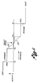
- FIG. 1 there is shown apparatus for moving a reading beam of light 11 in a radial direction relative to a rotating recording disc 13, to recover information from a selected target track on the disc.
- the disc includes a plurality of closely spaced, substantially circular and concentric recording tracks, and each track records a video signal representing one video frame, with a unique frame or track address signal located in each vertical interval (i.e., two address signals per track).
- the apparatus includes a spindle motor 15 for rotating the recording disc 13 at a prescribed constant angular velocity, and an optical system 17 and an objective lens 19 for focusing the reading beam 11 onto a selected track of the rotating disc.
- the reading beam is reflected by the disc, to produce a reflected beam 21 having an intensity that is modulated in accordance with the recorded information.
- the objective lens and optical system direct this reflected beam to a detector 23, which detects and demodulates the modulated intensity of the beam, to produce a baseband video signal corresponding to the recorded information.
- This video signal is coupled over line 25 to both a monitor 27 and an address recovery and estimator circuit 29.
- the monitor provides a real-time display of the video signal recovered from the target track, and the address recovery circuit detects the address signals in the successive vertical intervals of the video signal, using conventional techniques.
- the address recovery circuit then updates an address register 30 with each detected track address signal.
- the apparatus further includes a coarse positioning system and a fine positioning system for controllably moving the reading beam 11 radially relative to the disc 13, toward the selected target track on the disc.
- the coarse positioning system includes a carriage motor 31 and appropriate gearing 33 for moving the beam at a selected one of two relatively high radial velocities (e.g., 100 and 500 tracks per disc revolution).
- the fine positioning system includes a movable mirror (not shown) located in the optical system 17 for controllably adjusting the beam's point of impingement on the disc over a relatively small range (e.g., about 50 tracks in either direction).
- a function generator 37 compares this target address signal with the address signal currently being stored by the address register 30. In accordance with a prescribed algorithm that will be described below, the function generator determines the radial separation between the current track and the target track, and outputs appropriate control signals to controllably drive the carriage motor 31 and the movable mirror of the optical system 17 so as to move the reading beam 11 toward the target track. These control signals are sequenced such that the beam reaches the target track in a time substantially less than that achieved by prior apparatus of this kind.
- the carriage motor 31 is driven at a prescribed velocity (or sequence of velocities) until the reading beam 11 has been moved to within a prescribed number of tracks of the target track, after which the movable mirror of the optical system 17 is conditioned to incrementally jump the beam from one track to the next a plurality of times during each half revolution of the disc 13.
- This technique of moving the beam radially relative to the disc, and in particular moving it incrementally a prescribed plurality of times during each half revolution of the disc substantially reduces the nominal time required to reach the target track and recover the information recorded on it.
- the coarse positioning system further includes a track scan driver 39 and a carriage motor tachometer 41 for controllably driving the carriage motor 31 in the prescribed fashion.
- the function generator 37 outputs a plurality of velocity commands for coupling over lines 43a-d to the track scan driver, which, in turn, controllably adjusts a dc drive signal coupled over line 45 to the carriage motor.
- the tachometer feeds back to the track scan driver over line 47 a carriage tachometer signal indicating the carriage motor's angular velocity, to enhance control of that velocity.
- a dc tracking error signal is coupled to the track scan driver over line 49, to controllably move the carriage motor so as to reduce any steady state deflection of the movable mirror of the optical system 17.
- the track scan driver 39 is depicted in greater detail in FIG. 4. It receives the velocity commands on lines 43a-d from the function generator 37 and converts these signals to an appropriate dc drive signal for coupling over line 45 to the carriage motor 31.
- the driver includes a speed control digital-to-analog (D/A) converter 51 for converting two speed commands, received on lines 43a and 43b, to a corresponding dc voltage signal, and an analog switch 53 for directing the dc signal onto either a forward line 55 or a reverse line 57, in accordance with forward and reverse direction signals received on lines 43c and 43d from the function generator.
- a first inverting amplifier 59 sums the signal, if any, on the reverse line 57 with the dc tracking error signal supplied on line 49.
- a second inverting amplifier 61 sums the signal, if any, on the forward line 55 with both the output of the first amplifier 59 and the carriage tachometer signal supplied on line 47 from the tachometer 41.
- the output of the second amplifier 61 is coupled over line 63 to a power amplifier 65, which produces the carriage motor drive signal for output on line 45.
- the tracking controller 67 When the apparatus is operating in a mode in which the reading beam 11 is to be maintained in alignment with a selected track, the tracking controller 67 merely amplifies the tracking error signal and couples it directly to the movable mirror of the optical system 17, to form a conventional closed loop tracking servo for controllably aligning the beam with the track.
- the tracking error signal is uncoupled from the movable mirror, and a prescribed sequence of pulses is coupled in its place.
- the tracking controller also outputs the dc tracking error signal for coupling over line 49 to the track scan driver 39, so as to reduce any steady state deflection of the movable mirror by moving the carriage motor 31 in the appropriate direction.
- the tracking controller 67 is depicted in greater detail in FIG. 2. It includes a disable or switch circuit 79, an amplifier 81 and a power driver 83, for amplifying the tracking error signal supplied on line 77 and outputting it as the radial correction signal for coupling over line 69 to controllably position the movable mirror of the optical system 17 (FIG. 1).
- the tracking error signal is coupled through the disable circuit at all times except during the search mode of operation.
- the output of the disable circuit is coupled over line 85 to the negative input terminal of the amplifier, and the output of the amplifier is, in turn, coupled over line 87 to the power driver, which outputs the radial correction signal.
- the signal output on line 85 by the disable circuit is also coupled to a low-pass filter 89, to produce the dc tracking error signal for coupling on line 49 to the track scan driver 39 (FIG. 1).
- the tracking controller 67 includes a kick generator 97, a zero crossing detector 99, a jumps-down counter 101, and a flip-flop 103.
- a binary code indicating the number of tracks (e.g., 11 tracks) to be jumped during the next half revolution of the disc 13 is supplied on lines 73 from the function generator 37 and entered into the jumps-down counter.
- a jump command signal supplied on line 75 from the function generator is coupled to the set direct input terminal of the flip-flop. This sets the Q output signal into the logical "1" state, and this signal is coupled over line 105 to the OR gate 93, and in turn over line 95 to the disable circuit 79, to open the tracking servo loop.
- the Q ⁇ output signal of the flip-flop 103 is is coupled over line 107 to the kick generator 97, which responds by outputing a single pulse signal for coupling over line 109 to the positive input terminal of the amplifier 81.
- This pulse signal is coupled through the amplifier and power driver 83 to the movable mirror of the optical system 17, to accelerate the reading beam 11 in the direction of the target track.
- the zero crossing detector 99 monitors the open loop tracking error signal (FIG. 3b) supplied on line 77 and outputs a clock pulse each time it detects a track crossing by the beam. These successive clock pulses are coupled over line 111 to the clock terminal of the jumps-down counter 101, to decrement the stored count, accordingly. When the count reaches zero, the counter outputs a reset pulse for coupling over line 113 to the reset direct terminal of the flip-flop 103.
- the open loop tracking error signal (FIG. 3b) supplied on line 77 and outputs a clock pulse each time it detects a track crossing by the beam.
- the reset pulse coupled over line 113 to the reset direct terminal of the flip-flop 103 returns the Q ⁇ output signal to the logical "1" state, which triggers the kick generator 97 to output a pulse of opposite polarity to that of the original pulse, thereby decelerating the movable mirror.
- the reset pulse simultaneously returns the Q output signal of the flip-flop to the logical "0" state, so that the tracking servo loop is no longer disabled by the disable circuit 79 and the loop can again function to controllably align the reading beam 11 with the track then being scanned.
- the dc tracking error signal is coupled on line 49 to the track scan driver 39, to controllably move the carriage motor 31 so as to reduce the deflection of the movable mirror.
- the reading beam 11 preferably traverses the prescribed number of tracks in substantially less time than that required to rotate the disc 13 through a half revolution.
- the beam must traverse tracks at a speed greater than the speed at which track radius changes because of any disc eccentricity.
- the kick generator 97 can include two monostable multivibrator or one-shot circuits, one triggered by a positive-going transition and the other by a negative-going transition.
- the kick generator can further include appropriate gating circuits to ensure that the successive pulses it produces have the correct polarity to move the reading beam 11 in the direction of the target track. These gating circuits are responsive to the forward and reverse direction commands supplied on lines 43c and 43d, respectively.
- FIG. 5 is a schematic diagram depicting the radial velocity of the reading beam 11 relative to the disc 13, as a function of distance from the target track.
- a prescribed threshold D1 e.g., 1700 tracks
- the coarse positioning system which includes the carriage motor 31, drives the beam at a fast speed toward the target track.
- the apparatus accomplishes this by coupling a fast speed control signal over line 43b from the function generator 37 to the track scan driver 39, which in turn couples a dc drive signal of the appropriate magnitude and direction to the carriage motor.
- the tracking controller 67 is adapted to jump the reading beam 11 in only one direction.
- the distance thresholds are skewed on opposite sides of the target track such that the carriage motor 31 always comes to a stop with the beam impinging on a track located on the appropriate side of the target track.
- the beam simply "plays" into the target track at a rate of one track per revolution.
- step 127 the absolute value of the number N, i.e.,
- the address register 30 (FIG. 1) stores the most recently detected track address. This address is ordinarily updated twice during each revolution of the disc 13, i.e., after the reading beam 11 scans the segment of a track recording the vertical interval portion of the video signal. Since the beam sometimes traverses tracks at a relatively high velocity, and since the recorded address code ordinarily includes about 30 to 40 binary bits of information, the address frequently is not properly detected. When this has occurred in the past, prior systems typically continued to move the reading beam at the same velocity as before the address was missed. This frequently caused the beam to overshoot the target track, thereby increasing substantially the time required to reach the target track and recover the information recorded on it.
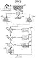
- FIG. 7 is a simplified flowchart of the process steps implemented by the address recovery and estimator circuit 29 (FIG. 1), in updating the address register 30 with either the most-recently detected current track address or an estimate of the current address.
- each sequence of detected data bits is monitored to determine whether or not it corresponds to a properly recovered address signal.
- each address signal contains about 33 bits of data, includng 20 address bits, one parity bit, and 12 "framing" bits, half at the beginning of the signal and half at the end.
- step 141 determines whether or not the framing bits correspond to a prescribed code. If they do, the data is presumed to be valid.
- step 141 determines the sequence of data bits to be invalid, then an address signal has not been properly recovered and the program proceeds to a series of steps that provide an estimate of the current track address. Specifically, step 151 determines whether a fast speed control signal or a medium speed control signal is being coupled to the track scan driver 39. If a fast signal is being coupled, step 153 defines a variable D to be 250, whereas, if a medium signal is is being coupled, step 155 defines D to be 50.
- the track address estimation procedure described above is followed only when the carriage motor 31 is driving the reading beam 11 at a medium or fast speed toward the target track. It is not used thereafter, when the movable mirror of the optical system 17 is incrementally jumping the beam from track to track. If the address recovery circuit 29 fails to properly recover an address signal at that time, the previously detected address is retained in the register 30.
- the present invention provides an improved apparatus for rapidly moving an information recovery device toward a prescribed target track on a rotating recording disc, to recover informatin recorded on it.
- the apparatus operates in substantially reduced time by first translating the information recovery device radially at a relatively high speed relative to the rotating disc, and then incrementally jumping the device from track to track a plurality of times during each disc revolution, until reaching the target track. Also, whenever the apparatus fails to properly recover a track address signal, it estimates the address of the track currently being scanned, and updates its control of the information recovery device's movement based on that estimate.
Landscapes
- Moving Of The Head For Recording And Reproducing By Optical Means (AREA)
- Moving Of Head For Track Selection And Changing (AREA)
- Management Or Editing Of Information On Record Carriers (AREA)
- Indexing, Searching, Synchronizing, And The Amount Of Synchronization Travel Of Record Carriers (AREA)
- Manufacturing Optical Record Carriers (AREA)
Applications Claiming Priority (5)
| Application Number | Priority Date | Filing Date | Title |
|---|---|---|---|
| US31602181A | 1981-10-28 | 1981-10-28 | |
| US316021 | 1981-10-28 | ||
| US33323681A | 1981-12-21 | 1981-12-21 | |
| US333236 | 1981-12-21 | ||
| EP85108998A EP0167177B1 (de) | 1981-10-28 | 1982-10-27 | Verfahren zur Wiedergabe von Informationen von einer ausgewählten Spur einer Aufzeichnungsplatte |
Related Parent Applications (3)
| Application Number | Title | Priority Date | Filing Date |
|---|---|---|---|
| EP85108998A Division EP0167177B1 (de) | 1981-10-28 | 1982-10-27 | Verfahren zur Wiedergabe von Informationen von einer ausgewählten Spur einer Aufzeichnungsplatte |
| EP85108998.7 Division | 1982-10-27 | ||
| EP82109936.3 Division | 1982-10-27 |
Publications (4)
| Publication Number | Publication Date |
|---|---|
| EP0495530A2 true EP0495530A2 (de) | 1992-07-22 |
| EP0495530A3 EP0495530A3 (en) | 1992-10-21 |
| EP0495530B1 EP0495530B1 (de) | 1995-03-15 |
| EP0495530B2 EP0495530B2 (de) | 1999-08-25 |
Family
ID=26980189
Family Applications (3)
| Application Number | Title | Priority Date | Filing Date |
|---|---|---|---|
| EP92104637A Expired - Lifetime EP0495530B2 (de) | 1981-10-28 | 1982-10-27 | Verfahren zur Wiedergabe von Information aus einer ausgewählten Spur einer Aufzeichnungsplatte |
| EP87111901A Withdrawn EP0302138A1 (de) | 1981-10-28 | 1982-10-27 | Verfahren zum Lokalisieren einer als Ziel ausgewählten, Information enthaltenden Spur auf einer Aufzeichnungsscheibe |
| EP82109936A Expired EP0078060B1 (de) | 1981-10-28 | 1982-10-27 | Verfahren und Vorrichtung zum Zurückgewinnen von Informationen von einer ausgewählten Spur auf einer Aufzeichnungsscheibe |
Family Applications After (2)
| Application Number | Title | Priority Date | Filing Date |
|---|---|---|---|
| EP87111901A Withdrawn EP0302138A1 (de) | 1981-10-28 | 1982-10-27 | Verfahren zum Lokalisieren einer als Ziel ausgewählten, Information enthaltenden Spur auf einer Aufzeichnungsscheibe |
| EP82109936A Expired EP0078060B1 (de) | 1981-10-28 | 1982-10-27 | Verfahren und Vorrichtung zum Zurückgewinnen von Informationen von einer ausgewählten Spur auf einer Aufzeichnungsscheibe |
Country Status (7)
| Country | Link |
|---|---|
| EP (3) | EP0495530B2 (de) |
| JP (3) | JPH01236479A (de) |
| KR (1) | KR870001118B1 (de) |
| AT (2) | ATE120024T1 (de) |
| DE (3) | DE3280460T2 (de) |
| HK (1) | HK15891A (de) |
| SG (1) | SG11291G (de) |
Families Citing this family (12)
| Publication number | Priority date | Publication date | Assignee | Title |
|---|---|---|---|---|
| JPS59119580A (ja) * | 1982-12-27 | 1984-07-10 | Toshiba Corp | デイスクレコ−ド再生装置 |
| DE3374734D1 (en) * | 1982-12-27 | 1988-01-07 | Toshiba Kk | Record disc reproducing apparatus |
| JPS6139239A (ja) * | 1984-07-28 | 1986-02-25 | Sony Corp | 光学式デイスクプレ−ヤ |
| US4716557A (en) * | 1985-03-08 | 1987-12-29 | Sanyo Electric Co., Ltd. | Apparatus for information retrieval from an optically readable storage disc |
| DE3520189A1 (de) * | 1985-06-05 | 1986-12-11 | Deutsche Thomson-Brandt Gmbh, 7730 Villingen-Schwenningen | Verfahren fuer das spurspringen bei spursuchvorgaengen und schaltungsanordnung zur durchfuehrung des verfahrens |
| DE3687019T2 (de) * | 1985-07-03 | 1993-03-11 | Pioneer Electronic Corp | Wiedergabeverfahren fuer informationen auf platten und deren identifikation. |
| JPS6220183A (ja) * | 1985-07-18 | 1987-01-28 | Toshiba Corp | トラツク飛び越し制御回路 |
| JPS6446270A (en) * | 1987-08-13 | 1989-02-20 | Pioneer Electronic Corp | Searching method in disk player |
| US5313446A (en) * | 1990-03-30 | 1994-05-17 | Canon Kabushiki Kaisha | Disc drive device having a head carriage |
| US5309417A (en) * | 1991-10-09 | 1994-05-03 | Nippon Conlux Co., Ltd. | Information recording/reproducing apparatus for optical information recording medium |
| JP3516598B2 (ja) * | 1998-10-29 | 2004-04-05 | パイオニア株式会社 | トラックジャンプ装置 |
| JP3781027B2 (ja) * | 2003-06-27 | 2006-05-31 | ティアック株式会社 | 光ディスク装置 |
Family Cites Families (16)
| Publication number | Priority date | Publication date | Assignee | Title |
|---|---|---|---|---|
| FR2336768A1 (fr) * | 1975-12-24 | 1977-07-22 | Honeywell Bull Soc Ind | Procede pour deplacer un systeme mobile par rapport a un support d'enregistrement d'informations et dispositif pour le mettre en oeuvre |
| FR2349191A1 (fr) * | 1976-04-23 | 1977-11-18 | Thomson Brandt | Lecteur optique de disque d'information comportant un dispositif d'acces automatique aux informations |
| JPS5948468B2 (ja) * | 1977-11-07 | 1984-11-27 | ティアック株式会社 | 情報再生装置 |
| JPS5916348B2 (ja) * | 1977-11-29 | 1984-04-14 | 日本ビクター株式会社 | 情報トラツク位置検索制御方法 |
| JPS5921101B2 (ja) * | 1977-11-29 | 1984-05-17 | 日本ビクター株式会社 | 情報信号再生装置 |
| JPS5913101B2 (ja) * | 1977-12-16 | 1984-03-27 | 株式会社日立製作所 | ランダムアクセス方法 |
| EP0007199B1 (de) * | 1978-06-30 | 1986-12-30 | Discovision Associates | Verfahren und Vorrichtung zur Informationswiedergabe von einem optisch lesbaren Speichermedium |
| JPS5538610A (en) * | 1978-09-04 | 1980-03-18 | Nec Corp | Magnetic disc unit |
| NL7810386A (nl) * | 1978-10-17 | 1980-04-21 | Philips Nv | Optische leesinrichting voor het uitlezen van een schijfvormige registratiedrager. |
| NL7812111A (nl) * | 1978-12-13 | 1980-06-17 | Philips Nv | Inrichting voor het optisch uitlezen van een schijf- vormige registratiedrager, in het bijzonder het snel opzoeken van een gewenst programmagedeelte. |
| JPS5611673A (en) * | 1979-07-03 | 1981-02-05 | Pioneer Video Corp | Address information retrieval method in information recording medium reproducing unit |
| US4352131A (en) * | 1980-02-29 | 1982-09-28 | U.S. Philips Corporation | Memory disc addressing device |
| JPS5769536A (en) * | 1980-10-17 | 1982-04-28 | Olympus Optical Co Ltd | Random access system for optical disc |
| JPS57172573A (en) * | 1981-04-17 | 1982-10-23 | Pioneer Video Corp | High-speed address information search system of recording information reproducing device |
| JPS57198586A (en) * | 1981-05-28 | 1982-12-06 | Sony Corp | Digital disc reproducing device |
| JPS5862868A (ja) * | 1981-10-09 | 1983-04-14 | Pioneer Video Corp | 情報再生装置における高速アドレス情報探索方式 |
-
1982
- 1982-10-27 KR KR8204825A patent/KR870001118B1/ko not_active Expired
- 1982-10-27 EP EP92104637A patent/EP0495530B2/de not_active Expired - Lifetime
- 1982-10-27 DE DE3280460T patent/DE3280460T2/de not_active Expired - Lifetime
- 1982-10-27 EP EP87111901A patent/EP0302138A1/de not_active Withdrawn
- 1982-10-27 AT AT92104637T patent/ATE120024T1/de not_active IP Right Cessation
- 1982-10-27 DE DE3280467T patent/DE3280467T3/de not_active Expired - Lifetime
- 1982-10-27 EP EP82109936A patent/EP0078060B1/de not_active Expired
- 1982-10-27 DE DE8282109936T patent/DE3279315D1/de not_active Expired
- 1982-10-27 AT AT85108998T patent/ATE114378T1/de active
-
1989
- 1989-02-01 JP JP1023642A patent/JPH01236479A/ja active Pending
-
1991
- 1991-02-22 SG SG112/91A patent/SG11291G/en unknown
- 1991-03-07 HK HK158/91A patent/HK15891A/en not_active IP Right Cessation
- 1991-06-26 JP JP3250147A patent/JP2617051B2/ja not_active Expired - Lifetime
- 1991-06-26 JP JP3250146A patent/JP2781683B2/ja not_active Expired - Lifetime
Also Published As
| Publication number | Publication date |
|---|---|
| ATE120024T1 (de) | 1995-04-15 |
| KR840002139A (ko) | 1984-06-11 |
| JPH06215500A (ja) | 1994-08-05 |
| DE3280467T3 (de) | 2000-01-05 |
| EP0302138A1 (de) | 1989-02-08 |
| EP0495530B1 (de) | 1995-03-15 |
| JPH01236479A (ja) | 1989-09-21 |
| EP0078060B1 (de) | 1988-12-28 |
| DE3279315D1 (en) | 1989-02-02 |
| DE3280460T2 (de) | 1995-06-14 |
| DE3280467T2 (de) | 1995-10-26 |
| SG11291G (en) | 1991-07-26 |
| DE3280467D1 (de) | 1995-04-20 |
| HK15891A (en) | 1991-03-15 |
| EP0078060A1 (de) | 1983-05-04 |
| DE3280460D1 (de) | 1995-01-05 |
| ATE114378T1 (de) | 1994-12-15 |
| JP2617051B2 (ja) | 1997-06-04 |
| JP2781683B2 (ja) | 1998-07-30 |
| JPH06215501A (ja) | 1994-08-05 |
| KR870001118B1 (ko) | 1987-06-08 |
| EP0495530B2 (de) | 1999-08-25 |
| EP0495530A3 (en) | 1992-10-21 |
Similar Documents
| Publication | Publication Date | Title |
|---|---|---|
| US4774699A (en) | Method and apparatus for positioning a read head to a selected track on a record disc | |
| US4701898A (en) | Method and apparatus for locating a selected track on a record disc | |
| EP0092169B1 (de) | Verfahren und Gerät zum Wiederauffinden von Informationen auf einer Videoplatte | |
| EP0035288B1 (de) | Optisches Spurfolgeverfahren und -system | |
| US4375091A (en) | Method and apparatus for information retrieval from an optically readable storage medium | |
| US5426625A (en) | Masking of tracking error signal abnormalities due to media defects | |
| EP0401973A2 (de) | Zuverlässige Spurüberkreuzungsdetektion in einem Datenspeichergerät | |
| USRE32574E (en) | Method and apparatus for information retrieval from an optically readable storage medium | |
| EP0495530B1 (de) | Verfahren zur Wiedergabe von Information aus einer ausgewählten Spur einer Aufzeichnungsplatte | |
| EP0007199B1 (de) | Verfahren und Vorrichtung zur Informationswiedergabe von einem optisch lesbaren Speichermedium | |
| EP0430456B1 (de) | Spursprünge-Steuervorrichtungen | |
| EP0167177B1 (de) | Verfahren zur Wiedergabe von Informationen von einer ausgewählten Spur einer Aufzeichnungsplatte | |
| US5384762A (en) | Focusing servo in an optical disk drive | |
| US4835753A (en) | Information playback system having an address search operation using a variable speed pickup positioning system | |
| US4506355A (en) | Method and apparatus for information retrieval from an optically readable storage medium | |
| EP0345917B1 (de) | Gerät und Verfahren zur Stillstandssteuerung eines Spindelmotors | |
| JPH0140424B2 (de) | ||
| EP0181436B1 (de) | Verfahren und Vorrichtung zur Informationswiedergabe von einem optisch lesbaren Speichermedium | |
| JPS59152561A (ja) | 記録情報再生装置 |
Legal Events
| Date | Code | Title | Description |
|---|---|---|---|
| PUAI | Public reference made under article 153(3) epc to a published international application that has entered the european phase |
Free format text: ORIGINAL CODE: 0009012 |
|
| 17P | Request for examination filed |
Effective date: 19920328 |
|
| AC | Divisional application: reference to earlier application |
Ref document number: 167177 Country of ref document: EP |
|
| AK | Designated contracting states |
Kind code of ref document: A2 Designated state(s): AT BE CH DE FR GB IT LI LU NL SE |
|
| PUAL | Search report despatched |
Free format text: ORIGINAL CODE: 0009013 |
|
| AK | Designated contracting states |
Kind code of ref document: A3 Designated state(s): AT BE CH DE FR GB IT LI LU NL SE |
|
| 17Q | First examination report despatched |
Effective date: 19931115 |
|
| GRAA | (expected) grant |
Free format text: ORIGINAL CODE: 0009210 |
|
| AC | Divisional application: reference to earlier application |
Ref document number: 167177 Country of ref document: EP |
|
| AK | Designated contracting states |
Kind code of ref document: B1 Designated state(s): AT BE CH DE FR GB IT LI LU NL SE |
|
| REF | Corresponds to: |
Ref document number: 120024 Country of ref document: AT Date of ref document: 19950415 Kind code of ref document: T |
|
| REF | Corresponds to: |
Ref document number: 3280467 Country of ref document: DE Date of ref document: 19950420 |
|
| ITF | It: translation for a ep patent filed | ||
| ET | Fr: translation filed | ||
| PLBI | Opposition filed |
Free format text: ORIGINAL CODE: 0009260 |
|
| PLBQ | Unpublished change to opponent data |
Free format text: ORIGINAL CODE: EPIDOS OPPO |
|
| 26 | Opposition filed |
Opponent name: INTERESSENGEMEINSCHAFT FUER RUNDFUNKSCHUTZRECHTE E Effective date: 19951215 |
|
| NLR1 | Nl: opposition has been filed with the epo |
Opponent name: INTERESSENGEMEINSCHAFT FUER RUNDFUNKSCHUTZRECHTE E |
|
| PLBF | Reply of patent proprietor to notice(s) of opposition |
Free format text: ORIGINAL CODE: EPIDOS OBSO |
|
| PLBF | Reply of patent proprietor to notice(s) of opposition |
Free format text: ORIGINAL CODE: EPIDOS OBSO |
|
| PLAW | Interlocutory decision in opposition |
Free format text: ORIGINAL CODE: EPIDOS IDOP |
|
| PLAW | Interlocutory decision in opposition |
Free format text: ORIGINAL CODE: EPIDOS IDOP |
|
| RAP2 | Party data changed (patent owner data changed or rights of a patent transferred) |
Owner name: DISCOVISION ASSOCIATES |
|
| PUAH | Patent maintained in amended form |
Free format text: ORIGINAL CODE: 0009272 |
|
| STAA | Information on the status of an ep patent application or granted ep patent |
Free format text: STATUS: PATENT MAINTAINED AS AMENDED |
|
| REG | Reference to a national code |
Ref country code: CH Ref legal event code: PFA Free format text: DISCOVISION ASSOCIATES,2183 FAIRVIEW ROAD, SUITE 211,COSTA MESA/CA (US) TRANSFER- DISCOVISION ASSOCIATES,2355 MAIN STREET, SUITE 200,IRVINE, CA 92614 (US) |
|
| 27A | Patent maintained in amended form |
Effective date: 19990825 |
|
| AK | Designated contracting states |
Kind code of ref document: B2 Designated state(s): AT BE CH DE FR GB IT LI LU NL SE |
|
| NLT2 | Nl: modifications (of names), taken from the european patent patent bulletin |
Owner name: DISCOVISION ASSOCIATES |
|
| REG | Reference to a national code |
Ref country code: CH Ref legal event code: AEN Free format text: AUFRECHTERHALTUNG DES PATENTES IN GEAENDERTER FORM |
|
| ITF | It: translation for a ep patent filed | ||
| ET3 | Fr: translation filed ** decision concerning opposition | ||
| PGFP | Annual fee paid to national office [announced via postgrant information from national office to epo] |
Ref country code: FR Payment date: 20011002 Year of fee payment: 20 |
|
| PGFP | Annual fee paid to national office [announced via postgrant information from national office to epo] |
Ref country code: SE Payment date: 20011003 Year of fee payment: 20 |
|
| PGFP | Annual fee paid to national office [announced via postgrant information from national office to epo] |
Ref country code: GB Payment date: 20011004 Year of fee payment: 20 Ref country code: DE Payment date: 20011004 Year of fee payment: 20 Ref country code: CH Payment date: 20011004 Year of fee payment: 20 Ref country code: AT Payment date: 20011004 Year of fee payment: 20 |
|
| PGFP | Annual fee paid to national office [announced via postgrant information from national office to epo] |
Ref country code: NL Payment date: 20011009 Year of fee payment: 20 |
|
| PGFP | Annual fee paid to national office [announced via postgrant information from national office to epo] |
Ref country code: LU Payment date: 20011012 Year of fee payment: 20 |
|
| PGFP | Annual fee paid to national office [announced via postgrant information from national office to epo] |
Ref country code: BE Payment date: 20011025 Year of fee payment: 20 |
|
| REG | Reference to a national code |
Ref country code: GB Ref legal event code: IF02 |
|
| PG25 | Lapsed in a contracting state [announced via postgrant information from national office to epo] |
Ref country code: LI Free format text: LAPSE BECAUSE OF EXPIRATION OF PROTECTION Effective date: 20021026 Ref country code: GB Free format text: LAPSE BECAUSE OF EXPIRATION OF PROTECTION Effective date: 20021026 Ref country code: CH Free format text: LAPSE BECAUSE OF EXPIRATION OF PROTECTION Effective date: 20021026 |
|
| PG25 | Lapsed in a contracting state [announced via postgrant information from national office to epo] |
Ref country code: NL Free format text: LAPSE BECAUSE OF EXPIRATION OF PROTECTION Effective date: 20021027 Ref country code: LU Free format text: LAPSE BECAUSE OF EXPIRATION OF PROTECTION Effective date: 20021027 Ref country code: AT Free format text: LAPSE BECAUSE OF EXPIRATION OF PROTECTION Effective date: 20021027 |
|
| REG | Reference to a national code |
Ref country code: CH Ref legal event code: PL |
|
| EUG | Se: european patent has lapsed |
Ref document number: 92104637.1 |
|
| REG | Reference to a national code |
Ref country code: GB Ref legal event code: PE20 Effective date: 20021026 |
|
| NLV7 | Nl: ceased due to reaching the maximum lifetime of a patent |
Effective date: 20021027 |