EP0495582A2 - Machine en forme de disque, à haut rendement et faible réactance comprenant un stator et un rotor - Google Patents
Machine en forme de disque, à haut rendement et faible réactance comprenant un stator et un rotor Download PDFInfo
- Publication number
- EP0495582A2 EP0495582A2 EP92300177A EP92300177A EP0495582A2 EP 0495582 A2 EP0495582 A2 EP 0495582A2 EP 92300177 A EP92300177 A EP 92300177A EP 92300177 A EP92300177 A EP 92300177A EP 0495582 A2 EP0495582 A2 EP 0495582A2
- Authority
- EP
- European Patent Office
- Prior art keywords
- stator
- rotor
- supporting means
- machine
- coil
- Prior art date
- Legal status (The legal status is an assumption and is not a legal conclusion. Google has not performed a legal analysis and makes no representation as to the accuracy of the status listed.)
- Granted
Links
Images



Classifications
-
- H—ELECTRICITY
- H02—GENERATION; CONVERSION OR DISTRIBUTION OF ELECTRIC POWER
- H02K—DYNAMO-ELECTRIC MACHINES
- H02K23/00—DC commutator motors or generators having mechanical commutator; Universal AC/DC commutator motors
- H02K23/54—Disc armature motors or generators
-
- H—ELECTRICITY
- H02—GENERATION; CONVERSION OR DISTRIBUTION OF ELECTRIC POWER
- H02K—DYNAMO-ELECTRIC MACHINES
- H02K1/00—Details of the magnetic circuit
- H02K1/02—Details of the magnetic circuit characterised by the magnetic material
-
- H—ELECTRICITY
- H02—GENERATION; CONVERSION OR DISTRIBUTION OF ELECTRIC POWER
- H02K—DYNAMO-ELECTRIC MACHINES
- H02K16/00—Machines with more than one rotor or stator
-
- H—ELECTRICITY
- H02—GENERATION; CONVERSION OR DISTRIBUTION OF ELECTRIC POWER
- H02K—DYNAMO-ELECTRIC MACHINES
- H02K19/00—Synchronous motors or generators
Definitions
- Disk-type motors and generators have some important advantages over standard cylindrical machines. These advantages include higher power density and lower noise levels. Ordinary cylindrical-type machines are inherently noisy due to radial flexure of the machine housing. In contrast, disk-type machines are inherently quieter because the housing flexure resulting from the attraction and repulsion forces between the stator and rotor poles is axial. As a result, the ends of the housing of a disk-type machine vibrate due to attraction and repulsion forces, but the cylindrical portion of the housing is much stiffer in the axial direction than in the radial direction so vibration is reduced. In addition it is much easier to isolate axial vibrations from the supporting structure than it is to isolate radial vibrations. In applications where silent electrical machine operation is necessary, such as in submarines, the disk-type motor is particularly advantageous.
- stator teeth in prior art designs are laminated in the axial and peripheral directions but are tapered in the radial direction.
- each radial layer of punchings must be a slightly different size than the previous layer.
- the material between stator teeth that supports the teeth must be of a different material so as to be non-magnetic, non-conducting, and light in weight for maximum efficiency and power density. Accurately pinning all of these separate laminations together to obtain a structurally sound stator assembly is also difficult. The same problems occur in constructing a rotor for such machines.
- Disk-type machines with one stator and one rotor have been made in small sizes, as described in U.S. patent 4,757,222 to Shiraki et al.
- axially directed magnetic forces become prohibitively large in machines of power greater than 100 kilowatts.
- Stator coils 108 are mounted on stator support disk 110 which is fixed to stator frame 112. Two axial air gaps 114 are defined between stator coils 108 and rotor coils 102. As shown in Figure 2, such machines may use a composite stator disk 202 with laminated iron teeth 204 arranged to form parallel sided slots 206 therebetween.
- the disadvantage of these prior art techniques is that the multiple stator windings increase the machine reactance and decrease efficiency, primarily because of the extra sets of stators and the increase in coil end turns required.
- stator section of the present invention uses micro-laminated stator teeth molded from cut steel particles and mounted on a large disk of composite fiber material which is the main structural component.
- the stator teeth are either molded separately and mounted in tapered slots in the disk, or are molded in place.
- the stator section of the present invention is designed to operate in a machine having an even number of axial air gaps, it has only a single winding.
- One layer of the winding is located on each:side of the central supporting disk and the ends of the windings are connected through connectors molded into or mounted on the disk. Multiturn coils may be employed by making a plurality of these connections for each coil.
- the interior rotor sections of the machine are likewise constructed on supporting rotor disks of composite material, and have pole pieces of cut steel particles molded into place during disk manufacture which are wound on both sides of the supporting disk.
- the pole pieces have damper slots in their faces for receiving a damper winding.
- An outer support cylinder at the circumference of the supporting rotor disk structurally supports components of the rotor. Cover pieces are provided at the sides of the rotor sections, facing the stator sections.
- the machine disclosed produces a practical design without sacrificing efficiency or reactance levels.
- the present invention is an improved electrical disk-type machine which includes an improved rotor and an improved stator.
- Figure 3 illustrates generally a preferred embodiment of the disk-type machine 302 of the present invention.
- the disk-type machine 302 has a rotating portion 304 and a static portion 306.
- Rotating portion 304 of disk-type machine 302 comprises shaft 308, two end rotor sections 310, and, optionally, one or more interior rotor sections 312.
- the interior rotor sections 312 and the end rotor sections 310 are provided with field windings 314.
- Each of the end rotor sections 310 and the interior rotor sections 312 are fixed to the shaft 308 and rotate with shaft 308 relative to the static portion 306 of disk-type machine 302.
- the static portion 306 of the disk-type machine 302 comprises stator frame 316, to which at least one stator section 402 is attached.
- Each stator section 402 includes stator disk 404 and stator coils 410.
- the stator disk 404 of each stator section 402 is fixed to the stator frame 316.
- End rotor sections 310 are located at opposite ends of the shaft 308.
- Stator sections 402 and interior rotor sections 312 are alternately mounted between the end rotor sections 310 along the length of shaft 308 so that in all cases a rotor field winding 314 faces each set of stator coils 410.
- Each pairing of a set of rotor field windings 314 and a set of stator coils 410 forms a primitive machine 318.
- six primitive machines 318 are formed using two end rotor sections 310, three stator sections 402, and two interior rotor sections 312. Any number of primitive machines 318 greater than one can be provided according to the present invention by providing the required number of additional stator sections 402 and/or interior rotor sections 312.
- a greater number of primitive machines will increase the power rating capability of the disk-type machine 302, but will also increase the weight of disk-type machine 302 and the inertia of rotating portion 304 of disk-type machine 302. Therefore, the number of primitive machines 318 to be included in the design of disk-type machine 302 will depend on the requirements of the particular application of disk-type machine 302.
- stator section of the present invention is shown generally at 402. Only a portion of the stator is shown in the drawing of Figure 4; the entire stator section 402 is actually in the shape of a circular ring open in the center.
- the stator section 402 is constructed on a stator disk 404 which is the main structural component of the stator section 402 and is preferably of composite fiber material.
- the material should be non-conductive and non-magnetic.
- Stator teeth 406 are mounted through the stator disk 404 in a generally circular, spaced relationship about the circular stator disk 404.
- the stator teeth 406 are formed in a wedge shape so that parallel channels 412 are formed between adjacent stator teeth 406 on each side of stator disk 404 to accommodate stator coils 410.
- the stator teeth 406 are molded in place when the stator disk 404 is formed, eliminating the need for supporting brackets.
- the stator teeth 406 could also be molded separately and mounted in tapered slots 408 provided on stator disk 404. The stator teeth 406 would be retained in slots 408 by supporting brackets (not shown).
- stator teeth 406 are micro-laminated from cut steel particles using materials and methods similar to those described in U.S. Patents 3,848,331 and 3,948,690 to N.H. Pavlik et al., the disclosures of which are incorporated herein by reference.
- stator teeth 406 greatly reduces eddy currents in the stator teeth 406.
- the use of stator teeth 406 formed in this manner also eliminates substantial difficulties in fabricating and assembling the stator teeth 406. Specifically, the manufacturing complexity that is eliminated by the use of the present method results from the fact that stator teeth in prior art designs are laminated in the axial and peripheral directions but are tapered in the radial direction. Thus, each radial layer of punchings must be a slightly different size than the previous layer.
- the material between stator teeth that supports the teeth of prior art designs was required to be of a different material so as to be non-magnetic, non-conducting, and light in weight for maximum efficiency and power density. Accurately pinning all of these separate laminations together to obtain a structurally sound stator assembly was also difficult in the prior art.
- stator disk 404 Connection through the stator disk 404 is necessary because the stator disk 404 will preferably be mounted to the stator frame of the machine around the outer circumference of stator disk 404; thus, there will be no clearance to allow the passage of coils 410 around the outer periphery of stator disk 404.
- the connectors 414 may in their simplest form comprise copper blocks which are molded into the stator disk 404 during production of stator disk 404.
- the connectors 414 will each have a provision for attaching either a turn or a start or finish lead of a coil 410 thereto.
- the conductors of coil 410 may, for example, be connected to a threaded protrusion in connector 414 by means of a nut, or the connectors 414 may be drilled and tapped so that the conductors of coil 410 may be bolted to the connector 414. While the connectors 414 have been described in simple form, those skilled in the art of machine design will recognize that the connectors 414 could be any type of known connector.
- stator disk 404 could be machined after production to accept connectors 414 if molding the connectors 414 into stator disk 404 is not desired.
- the number of connectors 414 which are provided in stator disk 404 will depend on the number of coils 410 to be provided on the stator disk 404 and the number of turns per coil. In general, one connector 414 will be needed for each coil 410 to facilitate connector of the finish lead of the previous coil 410 to the start lead of the present coil 410. An additional connector 414 will be needed for each turn in excess of one within coil 410.
- the stator section 402 in Figure 4 is shown structured for coils 410 having two turns each, so that two connectors 414 are provided for each coil 410. One connector 414 connects the start lead of the coil 410 to the finish lead of the previous coil 410, while the other connector 414 connects the end of the first turn within coil 410 to the beginning of the second turn within coil 410.
- stator section 402 could be constructed by merely providing holes passing through the stator disk 404, and then welding or otherwise directly connecting the ends of the coil turns together within these holes. In this embodiment, no special forming of the ends of the coil turns would be needed.
- the coils 410 are constructed generally in accordance with the prior art in that they are made up of loops consisting of twisted bundles of copper wire, each bundle being coated with insulating material to prevent conduction between loops.
- Each coil 410 has a start lead 502 and a finish lead 504.
- the coil 410 may be provided with any number of turns.
- the coil 410 shown in Figure 5 is provided with two turns, a first turn 506 and a second turn 508.
- the coil 410 does, however, differ from the prior art in several important respects.
- the upper end section 510 and the lower end section 512 are elongated to provide clearance for the thickness of stator disk 404 which will lie between the two coil halves.
- the radially outward end turn at upper end section 510 is cut between the end of first turn 506 and the beginning of second turn 508 after forming of the coil 410 to form connecting points 514, so that the coil 404 can be installed on stator disk 404 (shown in Figure 4).
- the coil 404 is mounted on the stator disk 404 by spreading the coil 404 at upper end section 510 and fitting each half of the coil 404 to an appropriate coil slot 412 (shown in Figure 4) on opposite sides of the stator disk 404 (shown in Figure 4).
- the connecting points 514 are then connected through the connectors 414 (shown in Figure 4).
- the start lead 502 is connected to the finish lead of the previous coil to be placed in series with the coil 404 being installed.
- the finish lead 504 of the coil 404 being installed is similarly connected to the start lead of the next coil through a connector 414 (shown in Figure 4).
- the stator section 402 of the present invention substantially reduces slot leakage reactance as compared to cylindrical machines or conventional disk-type machines.
- slot leakage flux in a cylindrical machine is compared to the slot leakage flux in a disk-type machine constructed to include the stator section 402 of the present invention.
- part A of Figure 6 a cross-section of a portion of a cylindrical machine stator is shown.
- the flux path in this stator is a loop beginning at the outside end of one stator tooth, passing through this stator tooth to the back iron of the stator, through the back iron to the adjacent stator tooth, through the adjacent stator tooth to its end, and across the slot containing the coil sides to the beginning point of the flux path.
- the magnetomotive forces H s tending to cause slot leakage flux increase substantially as R increases, R being a measure of radial distance.
- Part B of Figure 6 a cross section of a portion of the stator section 402 of the present invention is shown.
- the flux path in the stator section 402 lies from one end of a first stator tooth 406, through the first stator tooth 406 to the opposite side of stator disk 404, across slot 412 containing coil 410 to a second stator tooth 406 adjacent to the first stator tooth 406, through the second stator tooth 406 to the original side of stator disk 404, and across the slot 412 containing coil 410 to the starting point of the flux path.
- the graph accompanying Figure 6 shows the magnetomotive forces H s tending to cause slot leakage flux in the disk-type machine of the present invention. As can be seen in the graph, these forces are of smaller magnitude than the forces shown in the graph of part A, and the forces associated with the disk machine as shown in Part B also tend to be partially of opposing direction so that there is an offsetting of these forces.
- the interior rotor section 312 of the present invention uses the same general construction techniques as have been described with respect to the stator section 402.
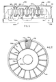
- the interior rotor section 312 is constructed on a supporting disk 702 which is attached to and rotates with shaft 308.
- Supporting disk 702 is preferably made of a composite fiber material.
- Supporting disk 702 is bounded at its circumference by an outer support cylinder 704.
- Rotor poles 706 are mounted through the supporting disk 702. In this case, 18 rotor poles 706 are shown although another number could be chosen.
- the rotor poles 706 are separated by interpolar supports 708.
- Rotor poles 706 are provided with damper slot openings 710.
- An outer damper shorting ring 712 and an inner damper shorting ring 714 are also mounted on the supporting disk 702 coaxially with the central longitudinal axis of shaft 308, as will be described in detail with reference to Figure 9.
- FIG 8 shows the construction of the rotor poles 706 and their installation in a portion of the interior rotor section 312, assembled in perspective view.
- the rotor poles are preferably constructed of magnetically conductive cut steel microlaminations in the same manner as described previously for the stator teeth 406 (shown in Figure 4).
- each rotor pole 706 is provided with a central pole body 802 and two pole faces 804.
- the central pole body 802 passes through the supporting disk 702 and extends beyond the sides of supporting disk 702 to provide rotor winding support areas 805 next to the sides of supporting disk 702.
- the pole faces 804 are provided with a plurality of damper slots 806.
- Each damper slot 806 has a damper slot opening 710 for providing access to the damper slot 806.
- Rotor poles 706 may be molded into the supporting disk 702 during the construction of the supporting disk 702, or the rotor poles 706 may be mounted to the supporting disk 702 by supporting brackets (not shown).
- FIG 9 shows a portion of a damper winding 902 adapted for installation on interior rotor section 312.
- Damper winding 902 comprises outer damper shorting ring 712, inner damper shorting ring 714, and a plurality of damper bars 904 radially mounted to electrically connect the inner damper shorting ring 714 and the outer damper shorting ring 712, thus forming a cage-type damper winding 902.
- Damper bars 904 are adapted to pass through the damper slots 806 in each pole face 804 of the rotor poles 706 so that a damper winding 902 can be installed on each side of the interior rotor section 312.
- the outer damper shorting ring 712 and the inner damper shorting ring 714 comprise circular assemblies of conductive metal and are located coaxially with each other and with the central longitudinal axis of shaft 308 (as shown in Figure 7).
- Figure 10 shows a portion of the interior rotor section 312 of the present invention, with field windings 314 installed about rotor poles 706 at rotor winding support areas 805 of rotor poles 706.
- Two field windings 314 are provided for each rotor pole 706 of the interior rotor section 312, with one field winding 314 mounted on each side of supporting disk 702.
- the field windings 314 may be connected as required through the supporting disk 702 with connectors 1004 using the connecting methods described for the stator portion 402 with reference to Figure 4.
- the connectors 1004 may in their simplest form comprise copper blocks which are molded into the supporting disk 702 during production of supporting disk 702.
- the connectors 1004 may be located wherever appropriate in the supporting disk 702 and will each have a provision for attaching a lead of a field winding 314 thereto.
- the lead of field winding 314 may, for example, be connected to a threaded protrusion in connector 1004 by means of a nut, or the connectors 1004 may be drilled and tapped so that a lead may be bolted to the connector 1004. While the connectors 1004 have been described in simple form, those skilled in the art of machine design will recognize that the connectors 1004 could be any type of known connector.
- the supporting disk 702 could be machined after production to accept connectors 1004 if molding the connectors 1004 into supporting disk 702 is not desired.
- damper winding 902 Also shown in Figure 10 is the installation of damper winding 902, with the damper bars 904 running through damper slots 806 of the rotor pole 706. While only a portion of one damper winding 902 is shown, it will be understood that a damper winding 902 is provided on each side of the interior rotor section 312 and that the damper windings 902 each form a complete circle, with the damper windings 902 being mounted in the damper slots 806 of each rotor pole 706.
- Figure 11 shows the supporting structural members which may be added to the interior rotor section 312.
- Interpolar supports 708 may be placed between adjacent rotor poles 706 to provide lateral bracing for the field windings 314 as the interior rotor section 312 rotates.
- These interpolar supports 708 should be constructed of insulating material.
- the outer support cylinder 704 is mounted to the circumferential edge of the supporting disk 702 to support the field windings 314 in the radial direction during rotation of the interior rotor section 312. Insulation 1102 is molded between the field windings 314 and the outer support cylinder 704.
- the outer support cylinder 704 will preferably be constructed from a lightweight yet structurally strong non-conductive material, such as a plastic or a composite fiber material.
- a cover disk 1104 may be provided at each side of supporting disk 702 to cover pole faces 804 of rotor poles 706 and thus provide axial support for the components of interior rotor section 312 that are attached to the sides of supporting disk 702.
- the cover disk 1104 is preferably a thin coating of plastic, composite fiber, or another non-conductive material.
- the cover disk 1104 can be molded in place after assembly of the interior rotor section 312, or the cover disk 1104 can be a removable part attached to each side of interior rotor section 312. In addition to providing structural support, the cover disk 1104 improves the aerodynamics of the interior rotor section 312.
- end rotor sections 310 may be conventional, or more preferably the end rotor sections 310 may be constructed in a manner similar to that described for interior rotor sections 312. Naturally, end rotor sections 310 will differ from interior rotor sections 312 in that they will be provided with field windings 314 and associated components on only the side that faces a stator section 402.
- End stator sections 1202 could be constructed conventionally or, more preferably, may be constructed in accordance with the stator designs described herein. However, in the embodiment shown in Figure 12, there is no need for the coils 1204 of the end stator sections 1202 to pass through a supporting disk, so that the end stator sections 1202 can be simplified relative to the stator sections 402 described previously with reference to Figure 4.
Landscapes
- Engineering & Computer Science (AREA)
- Power Engineering (AREA)
- Iron Core Of Rotating Electric Machines (AREA)
- Insulation, Fastening Of Motor, Generator Windings (AREA)
- Windings For Motors And Generators (AREA)
Applications Claiming Priority (2)
| Application Number | Priority Date | Filing Date | Title |
|---|---|---|---|
| US640752 | 1991-01-14 | ||
| US07/640,752 US5177392A (en) | 1991-01-14 | 1991-01-14 | High efficiency, low reactance disk-type machine including an improved rotor and stator |
Publications (3)
| Publication Number | Publication Date |
|---|---|
| EP0495582A2 true EP0495582A2 (fr) | 1992-07-22 |
| EP0495582A3 EP0495582A3 (en) | 1994-05-18 |
| EP0495582B1 EP0495582B1 (fr) | 1997-03-26 |
Family
ID=24569572
Family Applications (1)
| Application Number | Title | Priority Date | Filing Date |
|---|---|---|---|
| EP92300177A Expired - Lifetime EP0495582B1 (fr) | 1991-01-14 | 1992-01-09 | Machine en forme de disque, à haut rendement et faible réactance comprenant un stator et un rotor |
Country Status (7)
| Country | Link |
|---|---|
| US (1) | US5177392A (fr) |
| EP (1) | EP0495582B1 (fr) |
| JP (1) | JPH0556612A (fr) |
| KR (1) | KR920015676A (fr) |
| CA (1) | CA2059227A1 (fr) |
| DE (1) | DE69218470T2 (fr) |
| ES (1) | ES2099202T3 (fr) |
Cited By (8)
| Publication number | Priority date | Publication date | Assignee | Title |
|---|---|---|---|---|
| WO1998035423A1 (fr) * | 1997-02-07 | 1998-08-13 | Anton Knestel | Utilisation d'un enroulement toroidal dans une machine polyphasee |
| RU2131164C1 (ru) * | 1997-03-25 | 1999-05-27 | Криворотов Александр Семенович | Генератор |
| GB2358740A (en) * | 2000-01-28 | 2001-08-01 | Imp Ltd | Modular electric motor |
| US6909215B2 (en) | 2000-01-28 | 2005-06-21 | John Graham Bryant | Electric motor |
| WO2005124967A1 (fr) * | 2004-06-17 | 2005-12-29 | Sähkö-Rantek Oy | Machine electrique du type a flux axial |
| RU2286641C1 (ru) * | 2005-05-19 | 2006-10-27 | Алексей Владимирович Булычев | Электрическая машина (варианты) |
| RU2545510C2 (ru) * | 2013-03-04 | 2015-04-10 | Алексей Алексеевич Палей | Коллекторный электродвигатель |
| WO2015153894A1 (fr) * | 2014-04-02 | 2015-10-08 | Larry Carpenter | Générateur de courant électrique |
Families Citing this family (43)
| Publication number | Priority date | Publication date | Assignee | Title |
|---|---|---|---|---|
| US5396140A (en) * | 1993-05-28 | 1995-03-07 | Satcon Technology, Corp. | Parallel air gap serial flux A.C. electrical machine |
| WO1996004094A2 (fr) * | 1994-07-22 | 1996-02-15 | Woodward Richard C Jr | Machine electrique de type a disque |
| GB9505072D0 (en) * | 1995-03-14 | 1995-05-03 | Lucas Ind Plc | A winding end support for a rotary electrical component |
| US5982074A (en) | 1996-12-11 | 1999-11-09 | Advanced Technologies Int., Ltd. | Axial field motor/generator |
| US6411002B1 (en) * | 1996-12-11 | 2002-06-25 | Smith Technology Development | Axial field electric machine |
| JPH10304608A (ja) * | 1997-04-21 | 1998-11-13 | Hitachi Ltd | 電動機 |
| KR100229389B1 (ko) * | 1997-05-30 | 1999-11-01 | 전주범 | 도어 개폐장치 및 그 방법 |
| RU2127939C1 (ru) * | 1997-08-19 | 1999-03-20 | Предприятие "Технократ" | Электрический торцевой наборный генератор |
| US6348751B1 (en) * | 1997-12-12 | 2002-02-19 | New Generation Motors Corporation | Electric motor with active hysteresis-based control of winding currents and/or having an efficient stator winding arrangement and/or adjustable air gap |
| US6066908A (en) * | 1998-09-14 | 2000-05-23 | Woodward, Jr.; Richard C. | Disc-type brushless alternator |
| US6445105B1 (en) * | 1999-04-06 | 2002-09-03 | General Electric Company | Axial flux machine and method of fabrication |
| US20020089253A1 (en) * | 2001-01-11 | 2002-07-11 | Kudlacik Henry William | Winding support for use with a superconducting rotor and method for forming the same |
| US6713982B2 (en) * | 2001-02-20 | 2004-03-30 | E. I. Du Pont De Nemours And Company | Segmented induction electric machine with interdigiated disk-type rotor and stator construction |
| US20060038516A1 (en) * | 2001-02-20 | 2006-02-23 | Burse Ronald O | Segmented switched reluctance electric machine with interdigitated disk-type rotor and stator construction |
| US7098566B2 (en) * | 2001-05-24 | 2006-08-29 | Rajasingham Arjuna Indraes War | Axial gap electrical machine |
| US9124165B2 (en) * | 2001-11-14 | 2015-09-01 | Arjuna Indraeswaran Rajasingham | Axial gap electrical machine |
| US7064466B2 (en) * | 2001-11-27 | 2006-06-20 | Denso Corporation | Brushless rotary electric machine having tandem rotary cores |
| US7012349B1 (en) | 2002-04-04 | 2006-03-14 | R. E. Phelon Company, Inc. | Machined rotor assembly and method of making same |
| US6707221B2 (en) * | 2002-04-08 | 2004-03-16 | General Electric Company | Axial flux machine, stator and fabrication method |
| US6774530B2 (en) * | 2002-06-07 | 2004-08-10 | Briggs & Stratton Corporation | Winding assemblies for electrical machines |
| US6905101B1 (en) * | 2002-06-11 | 2005-06-14 | Chief Manufacturing Inc. | Adjustable, self-balancing flat panel display mounting system |
| US20040164695A1 (en) * | 2003-02-26 | 2004-08-26 | William M. Hallidy | Electrodynamic machines and components therefor and methods of making and using same |
| US20040164701A1 (en) * | 2003-02-26 | 2004-08-26 | William Hallidy | Electrodynamic machines and components therefor and methods of making and using same |
| AU2003300169A1 (en) * | 2003-02-26 | 2004-09-28 | William Hallidy | Electrodynamic machines and components therefor and methods of making and using same |
| US20050225191A1 (en) * | 2004-04-13 | 2005-10-13 | Walker James M | Magneto multiple pole charging system |
| JP2006204085A (ja) * | 2004-12-24 | 2006-08-03 | Sumitomo Electric Ind Ltd | アキシャルギャップ型超電導モータ |
| US7608965B2 (en) * | 2005-09-01 | 2009-10-27 | Wisconsin Alumni Research Foundation | Field controlled axial flux permanent magnet electrical machine |
| CA2549882A1 (fr) * | 2006-06-12 | 2007-12-12 | Msi Machineering Solutions Inc. | Moteur a reluctance commute par flux axial |
| GB0613570D0 (en) * | 2006-07-07 | 2006-08-16 | Imp Innovations Ltd | An electrical machine |
| JP4699961B2 (ja) * | 2006-08-30 | 2011-06-15 | 本田技研工業株式会社 | 回転電機用コイルとその製造方法、並びに回転電機とその製造方法 |
| CA2649190C (fr) * | 2007-01-05 | 2014-10-07 | Csav, Inc. | Montage autoequilibrant et evitant le contact avec une paroi pour positionner de maniere basculante un ecran plat electronique |
| US20100101879A1 (en) * | 2007-02-14 | 2010-04-29 | Mcvickers Jack C | Motor Battery Systems |
| US7576507B2 (en) * | 2007-02-14 | 2009-08-18 | Mcvickers Jack C | Motor battery systems |
| US7659680B1 (en) | 2007-02-14 | 2010-02-09 | Mcvickers Jack C | Motor battery systems |
| JP5221966B2 (ja) * | 2008-01-31 | 2013-06-26 | 本田技研工業株式会社 | 回転電機用コイルアッセンブリ、回転電機用ステータ、及び回転電機 |
| US20110031826A1 (en) * | 2009-08-06 | 2011-02-10 | General Electric Company | Permanent magnet machine and rotor |
| RU2484573C2 (ru) * | 2011-09-21 | 2013-06-10 | Закрытое Акционерное Общество "Новомет-Пермь" | Вентильный электродвигатель |
| RU2510121C2 (ru) * | 2012-03-26 | 2014-03-20 | Артем Валерьевич Бормотов | Модульная электрическая машина |
| US9608551B2 (en) * | 2015-08-17 | 2017-03-28 | Abb Schweiz Ag | Reducing peak fault output current in a DC power generation system |
| JP6609368B2 (ja) * | 2016-03-09 | 2019-11-20 | 日鍛バルブ株式会社 | 中空単相誘導モータ |
| US11043885B2 (en) * | 2016-07-15 | 2021-06-22 | Genesis Robotics And Motion Technologies Canada, Ulc | Rotary actuator |
| GB2559441A (en) * | 2017-09-15 | 2018-08-08 | De Innovation Lab Ltd | Electrical motor arrangement for electrical vehicles |
| TWI683509B (zh) * | 2018-05-17 | 2020-01-21 | 翁壽成 | 節能發電機組裝置 |
Family Cites Families (24)
| Publication number | Priority date | Publication date | Assignee | Title |
|---|---|---|---|---|
| US2734140A (en) * | 1956-02-07 | parker | ||
| FR1234263A (fr) * | 1959-05-12 | 1960-10-17 | Electronique & Automatisme Sa | Alternateur à haute fréquence |
| US3277323A (en) * | 1964-01-23 | 1966-10-04 | Louis W Parker | Axial airgap machines and improved cooling system therefor |
| US3469134A (en) * | 1965-07-31 | 1969-09-23 | Lloyd Dynamowerke Gmbh | Electrical machines |
| US3296475A (en) * | 1965-09-15 | 1967-01-03 | Louis W Parker | Dynamo-electric machines, and rotors therefor |
| US3567978A (en) * | 1969-10-24 | 1971-03-02 | Louis W Parker | Axial airgap motors with reduced iron losses |
| US3700944A (en) * | 1971-11-08 | 1972-10-24 | Ford Motor Co | Disc-type variable reluctance rotating machine |
| US3848331A (en) * | 1973-09-11 | 1974-11-19 | Westinghouse Electric Corp | Method of producing molded stators from steel particles |
| US3948690A (en) * | 1973-09-11 | 1976-04-06 | Westinghouse Electric Corporation | Molded magnetic cores utilizing cut steel particles |
| US4039875A (en) * | 1975-11-07 | 1977-08-02 | Computer Devices Corporation | Method and apparatus for interconnecting stator coils |
| US4198582A (en) * | 1977-06-24 | 1980-04-15 | Exxon Research & Engineering Co. | High performance stepper motor |
| US4237396A (en) * | 1977-10-06 | 1980-12-02 | P A Management Consultants Limited | Electromagnetic machines with permanent magnet excitation |
| US4392072A (en) * | 1978-09-13 | 1983-07-05 | General Electric Company | Dynamoelectric machine stator having articulated amorphous metal components |
| US4255684A (en) * | 1979-08-03 | 1981-03-10 | Mischler William R | Laminated motor stator structure with molded composite pole pieces |
| US4330727A (en) * | 1979-12-27 | 1982-05-18 | Claude Oudet | Electric step motor |
| US4327303A (en) * | 1980-09-29 | 1982-04-27 | Siemens-Allis, Inc. | Rotor assembly for a dynamoelectric machine |
| US4387335A (en) * | 1981-07-27 | 1983-06-07 | Fisher Charles B | Constant-frequency dynamo with stationary armature |
| JPS6184683U (fr) * | 1984-11-07 | 1986-06-04 | ||
| US4554491A (en) * | 1984-08-10 | 1985-11-19 | Msl Industries, Inc. | Brushless DC motor having a laminated stator with a single stator winding |
| US4620120A (en) * | 1984-11-02 | 1986-10-28 | Karsten Laing | Stator having tooth lamination strips lying between circular cylinders |
| FR2612704B1 (fr) * | 1987-03-18 | 1989-05-19 | Rose Robert | Moteur asynchrone pour vitesse variable avec double stator et rotor a grilles |
| US4959578A (en) * | 1987-11-24 | 1990-09-25 | Axial Electric, Inc. | Dual rotor axial air gap induction motor |
| WO1989012347A1 (fr) * | 1988-06-01 | 1989-12-14 | Pal Adam | Moteur electrique a induit en disque a noyau de fer |
| US5057726A (en) * | 1990-10-10 | 1991-10-15 | Westinghouse Electric Corp. | Structureborne vibration-compensated motor arrangement having back-to-back twin AC motors |
-
1991
- 1991-01-14 US US07/640,752 patent/US5177392A/en not_active Expired - Fee Related
-
1992
- 1992-01-09 EP EP92300177A patent/EP0495582B1/fr not_active Expired - Lifetime
- 1992-01-09 DE DE69218470T patent/DE69218470T2/de not_active Expired - Fee Related
- 1992-01-09 ES ES92300177T patent/ES2099202T3/es not_active Expired - Lifetime
- 1992-01-13 KR KR1019920000323A patent/KR920015676A/ko not_active Ceased
- 1992-01-13 CA CA002059227A patent/CA2059227A1/fr not_active Abandoned
- 1992-01-14 JP JP4024650A patent/JPH0556612A/ja not_active Withdrawn
Cited By (10)
| Publication number | Priority date | Publication date | Assignee | Title |
|---|---|---|---|---|
| WO1998035423A1 (fr) * | 1997-02-07 | 1998-08-13 | Anton Knestel | Utilisation d'un enroulement toroidal dans une machine polyphasee |
| RU2131164C1 (ru) * | 1997-03-25 | 1999-05-27 | Криворотов Александр Семенович | Генератор |
| GB2358740A (en) * | 2000-01-28 | 2001-08-01 | Imp Ltd | Modular electric motor |
| GB2358740B (en) * | 2000-01-28 | 2005-02-16 | Imp Ltd | Electric motor |
| US6909215B2 (en) | 2000-01-28 | 2005-06-21 | John Graham Bryant | Electric motor |
| WO2005124967A1 (fr) * | 2004-06-17 | 2005-12-29 | Sähkö-Rantek Oy | Machine electrique du type a flux axial |
| RU2286641C1 (ru) * | 2005-05-19 | 2006-10-27 | Алексей Владимирович Булычев | Электрическая машина (варианты) |
| RU2545510C2 (ru) * | 2013-03-04 | 2015-04-10 | Алексей Алексеевич Палей | Коллекторный электродвигатель |
| WO2015153894A1 (fr) * | 2014-04-02 | 2015-10-08 | Larry Carpenter | Générateur de courant électrique |
| US10014734B2 (en) | 2014-04-02 | 2018-07-03 | Larry Carpenter | Electric current generator/motor with dual stationary/rotating stators and rotor having horseshoe magnet/electromagnetic coils |
Also Published As
| Publication number | Publication date |
|---|---|
| KR920015676A (ko) | 1992-08-27 |
| US5177392A (en) | 1993-01-05 |
| JPH0556612A (ja) | 1993-03-05 |
| DE69218470D1 (de) | 1997-04-30 |
| CA2059227A1 (fr) | 1992-07-15 |
| EP0495582B1 (fr) | 1997-03-26 |
| ES2099202T3 (es) | 1997-05-16 |
| EP0495582A3 (en) | 1994-05-18 |
| DE69218470T2 (de) | 1997-10-23 |
Similar Documents
| Publication | Publication Date | Title |
|---|---|---|
| US5177392A (en) | High efficiency, low reactance disk-type machine including an improved rotor and stator | |
| US4114057A (en) | Dynamoelectric machine with inner and outer stators | |
| US4959578A (en) | Dual rotor axial air gap induction motor | |
| US4788465A (en) | Armature for DC motor | |
| US3237036A (en) | Commutating dynamo-electric machine | |
| US3529191A (en) | Homopolar machine having disklike rotor | |
| EP0429729A1 (fr) | Machines électriques à induit discoide comportant un noyau en fer | |
| AU628670B2 (en) | Rotor with reduced windage losses | |
| US5886449A (en) | Electrical machine | |
| US20060038461A1 (en) | Optimized air core armature | |
| US4228378A (en) | Wire wound disc armature for dynamoelectric machine | |
| US6191517B1 (en) | Brushless synchronous rotary electrical machine | |
| US3728566A (en) | Salient pole rotor construction with removable pole tips | |
| US5317227A (en) | Rotor with hollow cylindrical permanent magnet | |
| US4845398A (en) | Armature stator configuration for compound interaction/induction electric rotating machine | |
| GB1574255A (en) | Rotary electrical machine | |
| CA1115319A (fr) | Armature de machine dynamo-electrique | |
| WO2001013494A1 (fr) | Piles d'enroulements isolees pour bobines a enroulements de phase, utilisees dans des dispositifs electromoteurs | |
| KR102538380B1 (ko) | 전기기기 | |
| JP7543229B2 (ja) | アキシャルギャップ型回転電機のステータコア、アキシャルギャップ型回転電機のステータ製造方法 | |
| US20220393560A1 (en) | Electric motor | |
| JPH03285541A (ja) | コンデンサ誘導電動機 | |
| EP0151509A1 (fr) | Machines électriques comportant un induit discoide | |
| GB2242073A (en) | Stator coil assembly for electric motors | |
| GB2140629A (en) | Coil for electromagnetic apparatus |
Legal Events
| Date | Code | Title | Description |
|---|---|---|---|
| PUAI | Public reference made under article 153(3) epc to a published international application that has entered the european phase |
Free format text: ORIGINAL CODE: 0009012 |
|
| AK | Designated contracting states |
Kind code of ref document: A2 Designated state(s): BE DE ES FR GB IT |
|
| PUAL | Search report despatched |
Free format text: ORIGINAL CODE: 0009013 |
|
| AK | Designated contracting states |
Kind code of ref document: A3 Designated state(s): BE DE ES FR GB IT |
|
| 17P | Request for examination filed |
Effective date: 19941118 |
|
| 17Q | First examination report despatched |
Effective date: 19950119 |
|
| GRAH | Despatch of communication of intention to grant a patent |
Free format text: ORIGINAL CODE: EPIDOS IGRA |
|
| GRAH | Despatch of communication of intention to grant a patent |
Free format text: ORIGINAL CODE: EPIDOS IGRA |
|
| GRAA | (expected) grant |
Free format text: ORIGINAL CODE: 0009210 |
|
| AK | Designated contracting states |
Kind code of ref document: B1 Designated state(s): BE DE ES FR GB IT |
|
| PGFP | Annual fee paid to national office [announced via postgrant information from national office to epo] |
Ref country code: FR Payment date: 19970417 Year of fee payment: 7 |
|
| ET | Fr: translation filed | ||
| REF | Corresponds to: |
Ref document number: 69218470 Country of ref document: DE Date of ref document: 19970430 |
|
| REG | Reference to a national code |
Ref country code: ES Ref legal event code: FG2A Ref document number: 2099202 Country of ref document: ES Kind code of ref document: T3 |
|
| PG25 | Lapsed in a contracting state [announced via postgrant information from national office to epo] |
Ref country code: GB Free format text: LAPSE BECAUSE OF NON-PAYMENT OF DUE FEES Effective date: 19980109 |
|
| PG25 | Lapsed in a contracting state [announced via postgrant information from national office to epo] |
Ref country code: ES Free format text: LAPSE BECAUSE OF EXPIRATION OF PROTECTION Effective date: 19980110 |
|
| PLBE | No opposition filed within time limit |
Free format text: ORIGINAL CODE: 0009261 |
|
| PG25 | Lapsed in a contracting state [announced via postgrant information from national office to epo] |
Ref country code: BE Free format text: LAPSE BECAUSE OF NON-PAYMENT OF DUE FEES Effective date: 19980131 |
|
| 26N | No opposition filed | ||
| BERE | Be: lapsed |
Owner name: WESTINGHOUSE ELECTRIC CORP. Effective date: 19980131 |
|
| GBPC | Gb: european patent ceased through non-payment of renewal fee |
Effective date: 19980109 |
|
| PG25 | Lapsed in a contracting state [announced via postgrant information from national office to epo] |
Ref country code: DE Free format text: LAPSE BECAUSE OF NON-PAYMENT OF DUE FEES Effective date: 19981103 |
|
| PG25 | Lapsed in a contracting state [announced via postgrant information from national office to epo] |
Ref country code: FR Free format text: LAPSE BECAUSE OF NON-PAYMENT OF DUE FEES Effective date: 19990930 |
|
| REG | Reference to a national code |
Ref country code: FR Ref legal event code: ST |
|
| REG | Reference to a national code |
Ref country code: ES Ref legal event code: FD2A Effective date: 20000601 |
|
| PG25 | Lapsed in a contracting state [announced via postgrant information from national office to epo] |
Ref country code: IT Free format text: LAPSE BECAUSE OF NON-PAYMENT OF DUE FEES;WARNING: LAPSES OF ITALIAN PATENTS WITH EFFECTIVE DATE BEFORE 2007 MAY HAVE OCCURRED AT ANY TIME BEFORE 2007. THE CORRECT EFFECTIVE DATE MAY BE DIFFERENT FROM THE ONE RECORDED. Effective date: 20050109 |