EP0496063B2 - Siebfläche für eine Siebmaschine - Google Patents
Siebfläche für eine Siebmaschine Download PDFInfo
- Publication number
- EP0496063B2 EP0496063B2 EP91120873A EP91120873A EP0496063B2 EP 0496063 B2 EP0496063 B2 EP 0496063B2 EP 91120873 A EP91120873 A EP 91120873A EP 91120873 A EP91120873 A EP 91120873A EP 0496063 B2 EP0496063 B2 EP 0496063B2
- Authority
- EP
- European Patent Office
- Prior art keywords
- screen surface
- screen
- frame
- spring
- outer frame
- Prior art date
- Legal status (The legal status is an assumption and is not a legal conclusion. Google has not performed a legal analysis and makes no representation as to the accuracy of the status listed.)
- Expired - Lifetime
Links
- 238000012216 screening Methods 0.000 title claims abstract description 12
- 230000010355 oscillation Effects 0.000 claims 1
- 238000010276 construction Methods 0.000 description 3
- 238000007873 sieving Methods 0.000 description 2
- 239000013013 elastic material Substances 0.000 description 1
- 239000002184 metal Substances 0.000 description 1
Images


Classifications
-
- B—PERFORMING OPERATIONS; TRANSPORTING
- B07—SEPARATING SOLIDS FROM SOLIDS; SORTING
- B07B—SEPARATING SOLIDS FROM SOLIDS BY SIEVING, SCREENING, SIFTING OR BY USING GAS CURRENTS; SEPARATING BY OTHER DRY METHODS APPLICABLE TO BULK MATERIAL, e.g. LOOSE ARTICLES FIT TO BE HANDLED LIKE BULK MATERIAL
- B07B1/00—Sieving, screening, sifting, or sorting solid materials using networks, gratings, grids, or the like
- B07B1/46—Constructional details of screens in general; Cleaning or heating of screens
- B07B1/48—Stretching devices for screens
- B07B1/485—Devices for alternately stretching and sagging screening surfaces
-
- B—PERFORMING OPERATIONS; TRANSPORTING
- B07—SEPARATING SOLIDS FROM SOLIDS; SORTING
- B07B—SEPARATING SOLIDS FROM SOLIDS BY SIEVING, SCREENING, SIFTING OR BY USING GAS CURRENTS; SEPARATING BY OTHER DRY METHODS APPLICABLE TO BULK MATERIAL, e.g. LOOSE ARTICLES FIT TO BE HANDLED LIKE BULK MATERIAL
- B07B1/00—Sieving, screening, sifting, or sorting solid materials using networks, gratings, grids, or the like
- B07B1/28—Moving screens not otherwise provided for, e.g. swinging, reciprocating, rocking, tilting or wobbling screens
-
- B—PERFORMING OPERATIONS; TRANSPORTING
- B07—SEPARATING SOLIDS FROM SOLIDS; SORTING
- B07B—SEPARATING SOLIDS FROM SOLIDS BY SIEVING, SCREENING, SIFTING OR BY USING GAS CURRENTS; SEPARATING BY OTHER DRY METHODS APPLICABLE TO BULK MATERIAL, e.g. LOOSE ARTICLES FIT TO BE HANDLED LIKE BULK MATERIAL
- B07B1/00—Sieving, screening, sifting, or sorting solid materials using networks, gratings, grids, or the like
- B07B1/46—Constructional details of screens in general; Cleaning or heating of screens
Definitions
- the invention relates to a screen surface for a Screening machine, the first areas of elastic Screen area differs from second areas of the Swing the sieve surface.
- Sieving machines are known, the sieve surface of which is a cross member has, which are arranged parallel to each other and on the top of which is attached to the elastic sieve.
- everyone second cross member is on a first movement system and the intermediate crossmember on a second Fixed movement system that swing in opposite directions, so that the areas between the cross beams Sieve alternately stretched and compressed (DE-C-1206372).
- a screening machine it is Arranging two movement systems is complex.
- the object of the invention is a sieve surface of the beginning to improve the type mentioned so that with simple design only one movement system required and also the screen surface from individual elements is composed. It is also an object of the invention Screen area with two different movements conventional screening machines with a movement system to be able to attach later.
- the Screen surface made up of individual components is composed of a swinging driven have outer frame, on the inside of which at least an inner part is supported by spring elements, the Component screen area alternately on the frame and the or the spring-loaded inner parts is attached.
- the screen surface can be made up of individual Elements are composed, both of them Include motion systems in themselves, so the second Movement system does not need its own drive and further the individual sieve elements are easy to assemble and are interchangeable. It becomes an element system created that with the simplest construction Screening requirements and in production, assembly and repair is particularly easy. This screen area is Can be used on all conventional screening machines.
- such a system has the advantage that certain places on the screen surface different Sieve elements can be installed. So z. B. at the Place where the screenings are fed in, sieve elements can be used which have a different sieving work perform as subordinate sieve elements.
- a particularly simple and safe working construction is created when the resilient inner Parts form a rectangular frame, on the cross or Long sides of the screen surface is attached.
- This can the outer frame is divided by at least one cross strut that crosses the inner frame and on which the Screen surface is attached. It is also suggested that that at least one of the cross struts in recesses of the inner frame that has enough play for opposite movements of the inner frame and cross strut.
- the first embodiment according to FIG. 1 shows one outer rectangular frame 1, which by a cross strut 2nd is divided so that the frame forms two fields.
- Each Field is through an inner cross strut 3 as an inner part divided in the middle, arranged parallel to the cross strut 2 is.
- the inner cross struts 3 are connected by spring elements 4 the long sides 5 of the outer frame 1 attached.
- the cross strut 2 and the two inner cross struts 3 parallel to each other and these parts together with the long sides 5 of the frame 1 form four Fields, each of an elastic Components screen surface 8 are spanned, which at the Parts 2, 3 and 6 is attached.
- the outer frame 1 is together with the cross strut 2 drives a drive in such a way that the inner cross struts 3 due to their mass and both the arranged springs as well as the coordination between mass and swing springs differently. With that, the individual areas of the component screen surface 8 alternately compressed and stretched.
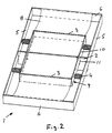
- the inner cross struts 3rd are part of an inner frame 9 by Spring elements 4 on the long sides 5 of the outer frame 1 is attached.
- the cross strut 2 due to slots 11 in the cross strut 2.
- the exemplary embodiment according to FIGS. 3 and 4 differs from that of FIG. 2 only in that the inner frame not in slots 11 of the cross strut 2 lies, but the long sides 10 of the inner frame 9th on its top form recesses 12 in which the Insert cross struts 2 of the outer frame. For education these recesses 12 are the long sides 10 of the inner Frame 9 downwards in a U-shape.
- the spring elements 4 can made of elastic material such as rubber or plastic or also be made of metal, in particular coil springs.
Landscapes
- Combined Means For Separation Of Solids (AREA)
- Paper (AREA)
- Control And Other Processes For Unpacking Of Materials (AREA)
- Coating With Molten Metal (AREA)
- Threshing Machine Elements (AREA)
- A Measuring Device Byusing Mechanical Method (AREA)
Description
- Fig. 1
- ein erstes Ausführungsbeispiel mit zwei getrennt elastisch gelagerten inneren Querstreben.
- Fig. 2
- ein zweites Ausführungsbeispiel mit einem rahmenförmigen inneren Teil
- Fig. 3
- den äußeren Rahmen eines dritten Ausführungsbeispiels und
- Fig. 4
- den inneren Rahmen des dritten Ausführungsbeispiels.
Claims (6)
- Siebfläche für eine Siebmaschine, bei der erste Bereiche der elastischen Siebfläche sich abweichend von zweiten Bereichen der Siebfläche schwingend bewegen, dadurch gekennzeichnet, daß die Siebfläche aus einzelnen Siebelementen zusammengesetzt ist, die einen schwingend angetriebenen äußeren Rahmen (1) aufweisen, an dem in dessen Innenbereich mindestens ein inneres Teil (3,9) durch Federelemente (4) gelagert ist, wobei die Siebelement-Siebfläche (8) abwechselnd an dem Rahmen (1) und dem oder den federnd gelagerten inneren Teilen (3,9) befestigt ist.
- Siebfläche nach Anspruch 1, dadurch gekennzeichnet, daß die federnd gelagerten inneren Teile (3,9) einen rechtwinkligen Rahmen (9) bilden, an dessen Quer- oder Längsseiten (3) die Siebelement-Siebfläche (8) befestigt ist.
- Siebfläche nach Anspruch 2, dadurch gekennzeichnet, daß der äußere Rahmen (1) von mindestens einer Querstrebe (2) unterteilt ist, die den inneren Rahmen (9) durchquert und an der die Siebelement-Siebfläche (8) befestigt ist.
- Siebfläche nach Anspruch 3, dadurch gekennzeichnet, daß wenigstens eine der Querstreben (2) in Ausnehmungen (12) des inneren Rahmens (9) einliegt, die genügend Spiel für entgegengesetzte Bewegungen von innerem Rahmen (9) und Querstrebe (2) lassen.
- Siebfläche nach einem der vorherigen Ansprüche, dadurch gekennzeichnet, daß in den unterteilten Innenbereichen des äußeren Rahmens (1) die federnd gelagerten inneren Teile (3) befestigt sind.
- Siebfläche nach einem der vorherigen Ansprüche, dadurch gekennzeichnet, daß die Teile (5,6) und Querstreben (2) des äußeren Rahmens (1) und der federnd gelagerten inneren Teile (3), an denen die Siebelement-Siebfläche (8) befestigt ist, zueinander parallel verlaufen.
Priority Applications (1)
| Application Number | Priority Date | Filing Date | Title |
|---|---|---|---|
| DE9117201U DE9117201U1 (de) | 1991-01-22 | 1991-12-05 | Siebfläche für eine Siebmaschine |
Applications Claiming Priority (2)
| Application Number | Priority Date | Filing Date | Title |
|---|---|---|---|
| DE4101710A DE4101710A1 (de) | 1991-01-22 | 1991-01-22 | Siebflaeche fuer eine siebmaschine |
| DE4101710 | 1991-01-22 |
Publications (4)
| Publication Number | Publication Date |
|---|---|
| EP0496063A2 EP0496063A2 (de) | 1992-07-29 |
| EP0496063A3 EP0496063A3 (en) | 1993-03-10 |
| EP0496063B1 EP0496063B1 (de) | 1994-11-17 |
| EP0496063B2 true EP0496063B2 (de) | 2000-07-05 |
Family
ID=6423444
Family Applications (1)
| Application Number | Title | Priority Date | Filing Date |
|---|---|---|---|
| EP91120873A Expired - Lifetime EP0496063B2 (de) | 1991-01-22 | 1991-12-05 | Siebfläche für eine Siebmaschine |
Country Status (5)
| Country | Link |
|---|---|
| US (1) | US5193689A (de) |
| EP (1) | EP0496063B2 (de) |
| AT (1) | ATE114121T1 (de) |
| DE (3) | DE4101710A1 (de) |
| ES (1) | ES2064029T3 (de) |
Cited By (1)
| Publication number | Priority date | Publication date | Assignee | Title |
|---|---|---|---|---|
| DE102014110055A1 (de) | 2014-07-17 | 2016-01-21 | Spaleck Gmbh & Co Kg | Siebmaschine mit kassettenartigen Siebflächenabschnitten |
Families Citing this family (10)
| Publication number | Priority date | Publication date | Assignee | Title |
|---|---|---|---|---|
| JP2597717Y2 (ja) * | 1993-06-21 | 1999-07-12 | 神鋼電機株式会社 | 振動篩機 |
| ES2076126B1 (es) * | 1993-12-22 | 1998-04-01 | Toribio Ranz Jesus Andres | Perfeccionamientos introducidos en mallas de clasificacion de aridos. |
| US5598931A (en) * | 1994-10-11 | 1997-02-04 | Nisshin Flour Milling Co., Ltd. | Sifter frame for powder particle sifter |
| NZ331538A (en) * | 1996-03-01 | 2000-03-27 | Bateman Process Equipment Ltd | Vibrating assembly for screening crushed rock |
| DE102006005967A1 (de) * | 2006-02-08 | 2007-08-09 | Bühler AG | Sieb |
| WO2010005546A1 (en) * | 2008-07-07 | 2010-01-14 | Derrick Corporation | Method and apparatuses for screening |
| AT511949B1 (de) * | 2012-02-29 | 2013-04-15 | Ife Aufbereitungstechnik Gmbh | Spannwellensieb |
| DE102013018873B3 (de) * | 2013-11-12 | 2014-11-27 | Schenck Process Gmbh | Siebvorrichtung |
| CN103586208A (zh) * | 2013-11-20 | 2014-02-19 | 河南太行振动机械股份有限公司 | 一种筛板紧固装置 |
| DE102017004508A1 (de) * | 2017-05-11 | 2018-11-15 | Hein, Lehmann Gmbh | Spannwellensiebmaschine |
Family Cites Families (10)
| Publication number | Priority date | Publication date | Assignee | Title |
|---|---|---|---|---|
| US44974A (en) * | 1864-11-08 | Samuel g- | ||
| US612521A (en) * | 1898-10-18 | X s sieve for gyratory boltsng and scalping k | ||
| US979685A (en) * | 1907-05-01 | 1910-12-27 | Edgar H Mumford | Riddle. |
| GB720437A (en) * | 1951-09-08 | 1954-12-22 | Miag Muehlenbau & Ind Gmbh | Improvements in or relating to slide frames for vibratory sieves |
| US2831576A (en) * | 1955-04-02 | 1958-04-22 | Brueckenbau Flender Gmbh | Sieving device |
| DE1206372B (de) * | 1964-09-26 | 1965-12-09 | Albert Wehner | Siebrost |
| AT379088B (de) * | 1984-02-10 | 1985-11-11 | Binder Co Ag | Siebvorrichtung |
| DE3512215A1 (de) * | 1985-04-03 | 1986-10-16 | Carl Schenck Ag, 6100 Darmstadt | Siebmaschine mit einem flexiblen siebbelag |
| AT383054B (de) * | 1985-07-24 | 1987-05-11 | Binder Co Ag | Siebvorrichtung |
| DE8816250U1 (de) * | 1988-01-14 | 1989-03-02 | Hein, Lehmann AG, 4000 Düsseldorf | Spannwell-Siebmaschine |
-
1991
- 1991-01-22 DE DE4101710A patent/DE4101710A1/de not_active Ceased
- 1991-12-05 EP EP91120873A patent/EP0496063B2/de not_active Expired - Lifetime
- 1991-12-05 ES ES91120873T patent/ES2064029T3/es not_active Expired - Lifetime
- 1991-12-05 DE DE9117201U patent/DE9117201U1/de not_active Expired - Lifetime
- 1991-12-05 DE DE59103541T patent/DE59103541D1/de not_active Expired - Fee Related
- 1991-12-05 AT AT91120873T patent/ATE114121T1/de not_active IP Right Cessation
-
1992
- 1992-01-22 US US07/823,566 patent/US5193689A/en not_active Expired - Lifetime
Cited By (2)
| Publication number | Priority date | Publication date | Assignee | Title |
|---|---|---|---|---|
| DE102014110055A1 (de) | 2014-07-17 | 2016-01-21 | Spaleck Gmbh & Co Kg | Siebmaschine mit kassettenartigen Siebflächenabschnitten |
| DE102014110055B4 (de) * | 2014-07-17 | 2020-03-19 | Spaleck GmbH & Co. Kommanditgesellschaft | Siebmaschine mit kassettenartigen Siebflächenabschnitten |
Also Published As
| Publication number | Publication date |
|---|---|
| ATE114121T1 (de) | 1994-12-15 |
| EP0496063A2 (de) | 1992-07-29 |
| DE9117201U1 (de) | 1997-03-20 |
| EP0496063B1 (de) | 1994-11-17 |
| DE4101710A1 (de) | 1992-07-23 |
| EP0496063A3 (en) | 1993-03-10 |
| US5193689A (en) | 1993-03-16 |
| ES2064029T3 (es) | 1995-01-16 |
| DE59103541D1 (de) | 1994-12-22 |
Similar Documents
| Publication | Publication Date | Title |
|---|---|---|
| EP0496063B2 (de) | Siebfläche für eine Siebmaschine | |
| DE102013018873B3 (de) | Siebvorrichtung | |
| AT6073U1 (de) | Mehrdecksiebmaschine | |
| DE3524895C1 (de) | Siebmaschine | |
| DE102020112209B4 (de) | Federsystem mit breitbandiger Isolationswirkung | |
| EP0405477B1 (de) | Siebmaschine | |
| DE3503125C2 (de) | Siebvorrichtung | |
| DE3611643C2 (de) | Peristaltische Schlauchpumpe | |
| DE69304171T2 (de) | Elektromotor und Apparat, der diesen Elektromotor enthält | |
| CH662601A5 (en) | Process for connecting free-standing walls, free-standing-wall portion and connecting column, and free-standing-wall arrangement for carrying out the process | |
| EP0206164A2 (de) | Siebmaschine mit einem an Querelementen befestigten Siebbelag | |
| DE2923662C2 (de) | Schwingsieb, insbesondere Kreisschwingsieb | |
| DE1946563U (de) | Veraenderliches verbindungsglied, insbesondere fuer vorrichtungen zur herstellung einer gegenseitigen abhaengigkeit und daempfervorrichtung fuer kreiselkompasse od. dgl. | |
| DE109466T1 (de) | Verstellbare konstruktion, zum beispiel aus miteinander verbundenen platten. | |
| DE69808235T2 (de) | Webstuhlaufhängung zur erhöhung der Stabilität des Webstuhles beim Betrieb | |
| AT400533B (de) | Spannwellensieb | |
| DE3226574C1 (de) | Siebmaschine | |
| DE3221344C1 (de) | Siebmaschine | |
| AT387342B (de) | Siebmaschinenabdichtung | |
| DE1131162B (de) | Siebrost | |
| DE2425953C3 (de) | Niedrig bauende Siebmaschine | |
| EP1957210A1 (de) | Flexible feinsiebmatte | |
| DE3326481C1 (de) | Siebmaschine | |
| DE683172C (de) | Schwunggewichtsloser Plansichter | |
| AT216437B (de) | Schwingvorrichtung, insbesondere Schwingsieb oder Schwingförderer |
Legal Events
| Date | Code | Title | Description |
|---|---|---|---|
| PUAI | Public reference made under article 153(3) epc to a published international application that has entered the european phase |
Free format text: ORIGINAL CODE: 0009012 |
|
| AK | Designated contracting states |
Kind code of ref document: A2 Designated state(s): AT BE DE ES FR GB IT NL |
|
| PUAL | Search report despatched |
Free format text: ORIGINAL CODE: 0009013 |
|
| AK | Designated contracting states |
Kind code of ref document: A3 Designated state(s): AT BE DE ES FR GB IT NL |
|
| 17P | Request for examination filed |
Effective date: 19930204 |
|
| 17Q | First examination report despatched |
Effective date: 19930609 |
|
| GRAA | (expected) grant |
Free format text: ORIGINAL CODE: 0009210 |
|
| AK | Designated contracting states |
Kind code of ref document: B1 Designated state(s): AT BE DE ES FR GB IT NL |
|
| PG25 | Lapsed in a contracting state [announced via postgrant information from national office to epo] |
Ref country code: FR Free format text: LAPSE BECAUSE OF NON-PAYMENT OF DUE FEES Effective date: 19941117 |
|
| REF | Corresponds to: |
Ref document number: 114121 Country of ref document: AT Date of ref document: 19941215 Kind code of ref document: T |
|
| ET | Fr: translation filed | ||
| REF | Corresponds to: |
Ref document number: 59103541 Country of ref document: DE Date of ref document: 19941222 |
|
| GBT | Gb: translation of ep patent filed (gb section 77(6)(a)/1977) |
Effective date: 19941129 |
|
| ITF | It: translation for a ep patent filed | ||
| REG | Reference to a national code |
Ref country code: ES Ref legal event code: FG2A Ref document number: 2064029 Country of ref document: ES Kind code of ref document: T3 |
|
| PLBI | Opposition filed |
Free format text: ORIGINAL CODE: 0009260 |
|
| 26 | Opposition filed |
Opponent name: CARL SCHENCK AG Effective date: 19950815 Opponent name: BINDER & CO. AKTIENGESELLSCHAFT Effective date: 19950811 |
|
| NLR1 | Nl: opposition has been filed with the epo |
Opponent name: CARL SCHENCK AG Opponent name: BINDER & CO. AKTIENGESELLSCHAFT |
|
| PLBF | Reply of patent proprietor to notice(s) of opposition |
Free format text: ORIGINAL CODE: EPIDOS OBSO |
|
| PLBF | Reply of patent proprietor to notice(s) of opposition |
Free format text: ORIGINAL CODE: EPIDOS OBSO |
|
| PLBO | Opposition rejected |
Free format text: ORIGINAL CODE: EPIDOS REJO |
|
| APAC | Appeal dossier modified |
Free format text: ORIGINAL CODE: EPIDOS NOAPO |
|
| APAE | Appeal reference modified |
Free format text: ORIGINAL CODE: EPIDOS REFNO |
|
| PGFP | Annual fee paid to national office [announced via postgrant information from national office to epo] |
Ref country code: FR Payment date: 19971112 Year of fee payment: 7 |
|
| PGFP | Annual fee paid to national office [announced via postgrant information from national office to epo] |
Ref country code: GB Payment date: 19971128 Year of fee payment: 7 |
|
| PGFP | Annual fee paid to national office [announced via postgrant information from national office to epo] |
Ref country code: BE Payment date: 19971208 Year of fee payment: 7 |
|
| PGFP | Annual fee paid to national office [announced via postgrant information from national office to epo] |
Ref country code: ES Payment date: 19971211 Year of fee payment: 7 |
|
| PGFP | Annual fee paid to national office [announced via postgrant information from national office to epo] |
Ref country code: NL Payment date: 19971231 Year of fee payment: 7 |
|
| PG25 | Lapsed in a contracting state [announced via postgrant information from national office to epo] |
Ref country code: GB Free format text: LAPSE BECAUSE OF NON-PAYMENT OF DUE FEES Effective date: 19981205 |
|
| PG25 | Lapsed in a contracting state [announced via postgrant information from national office to epo] |
Ref country code: ES Free format text: LAPSE BECAUSE OF EXPIRATION OF PROTECTION Effective date: 19981207 |
|
| PG25 | Lapsed in a contracting state [announced via postgrant information from national office to epo] |
Ref country code: BE Free format text: LAPSE BECAUSE OF NON-PAYMENT OF DUE FEES Effective date: 19981231 |
|
| BERE | Be: lapsed |
Owner name: HEIN LEHMANN TRENN- UND FORDERTECHNIK G.M.B.H. Effective date: 19981231 Owner name: ISENMANN SIEBE G.M.B.H. Effective date: 19981231 |
|
| PG25 | Lapsed in a contracting state [announced via postgrant information from national office to epo] |
Ref country code: NL Free format text: LAPSE BECAUSE OF NON-PAYMENT OF DUE FEES Effective date: 19990701 |
|
| GBPC | Gb: european patent ceased through non-payment of renewal fee |
Effective date: 19981205 |
|
| NLV4 | Nl: lapsed or anulled due to non-payment of the annual fee |
Effective date: 19990701 |
|
| REG | Reference to a national code |
Ref country code: FR Ref legal event code: ST |
|
| APAC | Appeal dossier modified |
Free format text: ORIGINAL CODE: EPIDOS NOAPO |
|
| PLAW | Interlocutory decision in opposition |
Free format text: ORIGINAL CODE: EPIDOS IDOP |
|
| PUAH | Patent maintained in amended form |
Free format text: ORIGINAL CODE: 0009272 |
|
| STAA | Information on the status of an ep patent application or granted ep patent |
Free format text: STATUS: PATENT MAINTAINED AS AMENDED |
|
| 27A | Patent maintained in amended form |
Effective date: 20000705 |
|
| AK | Designated contracting states |
Kind code of ref document: B2 Designated state(s): AT BE DE ES FR GB IT NL |
|
| EN | Fr: translation not filed | ||
| REG | Reference to a national code |
Ref country code: ES Ref legal event code: FD2A Effective date: 20010301 |
|
| APAH | Appeal reference modified |
Free format text: ORIGINAL CODE: EPIDOSCREFNO |
|
| PG25 | Lapsed in a contracting state [announced via postgrant information from national office to epo] |
Ref country code: IT Free format text: LAPSE BECAUSE OF NON-PAYMENT OF DUE FEES Effective date: 20051205 |
|
| PLAB | Opposition data, opponent's data or that of the opponent's representative modified |
Free format text: ORIGINAL CODE: 0009299OPPO |
|
| PGFP | Annual fee paid to national office [announced via postgrant information from national office to epo] |
Ref country code: AT Payment date: 20081211 Year of fee payment: 18 |
|
| PGFP | Annual fee paid to national office [announced via postgrant information from national office to epo] |
Ref country code: DE Payment date: 20081127 Year of fee payment: 18 |
|
| PG25 | Lapsed in a contracting state [announced via postgrant information from national office to epo] |
Ref country code: AT Free format text: LAPSE BECAUSE OF NON-PAYMENT OF DUE FEES Effective date: 20091205 |
|
| PG25 | Lapsed in a contracting state [announced via postgrant information from national office to epo] |
Ref country code: DE Free format text: LAPSE BECAUSE OF NON-PAYMENT OF DUE FEES Effective date: 20100701 |