EP0496096B1 - Procédé d'élimination des oxydes d'azote d'un gaz d'échappement - Google Patents
Procédé d'élimination des oxydes d'azote d'un gaz d'échappement Download PDFInfo
- Publication number
- EP0496096B1 EP0496096B1 EP91122044A EP91122044A EP0496096B1 EP 0496096 B1 EP0496096 B1 EP 0496096B1 EP 91122044 A EP91122044 A EP 91122044A EP 91122044 A EP91122044 A EP 91122044A EP 0496096 B1 EP0496096 B1 EP 0496096B1
- Authority
- EP
- European Patent Office
- Prior art keywords
- ammonia
- catalyst zone
- waste gas
- nitrogen oxides
- catalyst
- Prior art date
- Legal status (The legal status is an assumption and is not a legal conclusion. Google has not performed a legal analysis and makes no representation as to the accuracy of the status listed.)
- Expired - Lifetime
Links
- MWUXSHHQAYIFBG-UHFFFAOYSA-N nitrogen oxide Inorganic materials O=[N] MWUXSHHQAYIFBG-UHFFFAOYSA-N 0.000 title claims abstract description 93
- 238000000034 method Methods 0.000 title claims abstract description 65
- 239000002912 waste gas Substances 0.000 title claims 16
- QGZKDVFQNNGYKY-UHFFFAOYSA-N Ammonia Chemical compound N QGZKDVFQNNGYKY-UHFFFAOYSA-N 0.000 claims abstract description 218
- 239000003054 catalyst Substances 0.000 claims abstract description 95
- 229910021529 ammonia Inorganic materials 0.000 claims abstract description 94
- 239000007789 gas Substances 0.000 abstract description 60
- 238000006243 chemical reaction Methods 0.000 abstract description 14
- 229910000069 nitrogen hydride Inorganic materials 0.000 description 11
- 238000006722 reduction reaction Methods 0.000 description 11
- 238000001179 sorption measurement Methods 0.000 description 10
- 239000003638 chemical reducing agent Substances 0.000 description 6
- XLYOFNOQVPJJNP-UHFFFAOYSA-N water Chemical compound O XLYOFNOQVPJJNP-UHFFFAOYSA-N 0.000 description 5
- CURLTUGMZLYLDI-UHFFFAOYSA-N Carbon dioxide Chemical compound O=C=O CURLTUGMZLYLDI-UHFFFAOYSA-N 0.000 description 4
- 230000007423 decrease Effects 0.000 description 4
- 229910001868 water Inorganic materials 0.000 description 4
- 238000003795 desorption Methods 0.000 description 3
- 238000010586 diagram Methods 0.000 description 3
- 239000003546 flue gas Substances 0.000 description 3
- 239000010457 zeolite Substances 0.000 description 3
- IJGRMHOSHXDMSA-UHFFFAOYSA-N Atomic nitrogen Chemical compound N#N IJGRMHOSHXDMSA-UHFFFAOYSA-N 0.000 description 2
- UGFAIRIUMAVXCW-UHFFFAOYSA-N Carbon monoxide Chemical compound [O+]#[C-] UGFAIRIUMAVXCW-UHFFFAOYSA-N 0.000 description 2
- JCXJVPUVTGWSNB-UHFFFAOYSA-N Nitrogen dioxide Chemical compound O=[N]=O JCXJVPUVTGWSNB-UHFFFAOYSA-N 0.000 description 2
- RAHZWNYVWXNFOC-UHFFFAOYSA-N Sulphur dioxide Chemical compound O=S=O RAHZWNYVWXNFOC-UHFFFAOYSA-N 0.000 description 2
- 229910021536 Zeolite Inorganic materials 0.000 description 2
- 229910002092 carbon dioxide Inorganic materials 0.000 description 2
- 230000003197 catalytic effect Effects 0.000 description 2
- 238000010531 catalytic reduction reaction Methods 0.000 description 2
- 238000004140 cleaning Methods 0.000 description 2
- 238000002485 combustion reaction Methods 0.000 description 2
- HNPSIPDUKPIQMN-UHFFFAOYSA-N dioxosilane;oxo(oxoalumanyloxy)alumane Chemical compound O=[Si]=O.O=[Al]O[Al]=O HNPSIPDUKPIQMN-UHFFFAOYSA-N 0.000 description 2
- 230000001105 regulatory effect Effects 0.000 description 2
- 238000011144 upstream manufacturing Methods 0.000 description 2
- 238000010521 absorption reaction Methods 0.000 description 1
- 239000003570 air Substances 0.000 description 1
- QVGXLLKOCUKJST-UHFFFAOYSA-N atomic oxygen Chemical compound [O] QVGXLLKOCUKJST-UHFFFAOYSA-N 0.000 description 1
- 239000001569 carbon dioxide Substances 0.000 description 1
- 239000000919 ceramic Substances 0.000 description 1
- 230000000052 comparative effect Effects 0.000 description 1
- 238000002474 experimental method Methods 0.000 description 1
- 239000007788 liquid Substances 0.000 description 1
- 229910052757 nitrogen Inorganic materials 0.000 description 1
- QJGQUHMNIGDVPM-UHFFFAOYSA-N nitrogen group Chemical group [N] QJGQUHMNIGDVPM-UHFFFAOYSA-N 0.000 description 1
- QGLKJKCYBOYXKC-UHFFFAOYSA-N nonaoxidotritungsten Chemical compound O=[W]1(=O)O[W](=O)(=O)O[W](=O)(=O)O1 QGLKJKCYBOYXKC-UHFFFAOYSA-N 0.000 description 1
- 239000001301 oxygen Substances 0.000 description 1
- 229910052760 oxygen Inorganic materials 0.000 description 1
- 230000002265 prevention Effects 0.000 description 1
- 239000011949 solid catalyst Substances 0.000 description 1
- 230000001052 transient effect Effects 0.000 description 1
- 229910001930 tungsten oxide Inorganic materials 0.000 description 1
- LEONUFNNVUYDNQ-UHFFFAOYSA-N vanadium atom Chemical compound [V] LEONUFNNVUYDNQ-UHFFFAOYSA-N 0.000 description 1
- 229910001935 vanadium oxide Inorganic materials 0.000 description 1
Images



Classifications
-
- B—PERFORMING OPERATIONS; TRANSPORTING
- B01—PHYSICAL OR CHEMICAL PROCESSES OR APPARATUS IN GENERAL
- B01D—SEPARATION
- B01D53/00—Separation of gases or vapours; Recovering vapours of volatile solvents from gases; Chemical or biological purification of waste gases, e.g. engine exhaust gases, smoke, fumes, flue gases, aerosols
- B01D53/34—Chemical or biological purification of waste gases
- B01D53/74—General processes for purification of waste gases; Apparatus or devices specially adapted therefor
- B01D53/86—Catalytic processes
- B01D53/8621—Removing nitrogen compounds
- B01D53/8625—Nitrogen oxides
Definitions
- the invention relates to a method for removing nitrogen oxides from an exhaust gas by selective reduction with ammonia in a catalyst zone.
- the SCR (selective catalytic reduction) process is known for reducing nitrogen oxide emissions and has become increasingly important.
- the nitrogen oxides contained in the combustion exhaust gases (hereinafter simply referred to as "NO") are reduced with ammonia on a catalyst.
- the active component this usually contains vanadium and / or tungsten oxide on a ceramic carrier. Zeolites are also suitable as active components.
- the stationary SCR process is usually carried out in such a way that 0.8 times the stoichiometrically required amount of ammonia is added to the exhaust gas to be treated before it enters the reactor.
- This sub-stoichiometric amount of ammonia avoids an undesirable "ammonia slip" (i.e. an escape of unreacted ammonia from the end of the catalyst zone), as would occur with a larger amount of ammonia, but the degree of NO reduction is limited to approximately 80%.
- DE-A-37 44 388 discloses a process for removing nitrogen oxides from exhaust gases by selective reduction with ammonia in a catalyst zone.
- the exhaust gas is periodically passed through the reaction zone alternately in the opposite direction of flow.
- the exhaust gas is fed in together with a stoichiometric amount of ammonia, based on the nitrogen oxides.
- the ammonia feed is cut off before unreacted ammonia leaves the reaction zone together with the exhaust gas, and the flow direction of the exhaust gases is then reversed. With this method, however, ammonia slip cannot be avoided with certainty.
- DE-A-35 05 354 describes a method and a device for removing undesired gaseous components from a flue gas.
- ammonia is supplied in stoichiometric amounts before the flue gas is fed to the catalyst. For this reason, ammonia slip can practically not occur in this process and no information about it is given Prevention made. However, the degree of NO reduction in the process is unsatisfactory.
- the invention is therefore based on the object of specifying a method of the type mentioned at the outset in which the ammonia slip can be reliably avoided while achieving a very high NO conversion.
- the ammonia slip is avoided in that between the end of the catalyst zone where the exhaust gas enters and the location of the ammonia entry into the catalyst zone there is a buffer zone which is practically ammonia-free if that exhaust gas entry end of the catalyst zone after the reversal of the flow direction of the exhaust gas again becomes the exhaust gas outlet end of the catalyst zone.
- the location of the ammonia entry into the catalyst zone is arranged downstream of the location of the exhaust gas entry into this zone, at least two sub-zones of the catalyst result.
- the exhaust gas to be treated and a gaseous ammonia-containing reducing agent are fed in repeated cycles of four phases I to IV in each case to the partial zones of the catalyst in such a way that, during phases I and III, the exhaust gas from an upstream partial zone and the reducing agent from an downstream side thereof located sub-zone is supplied and the supply of reducing agent is interrupted during phases II and IV.
- phase III and IV the direction of flow of the exhaust gas and reducing agent is reversed, and the exhaust gas is then fed to that subzone which was arranged downstream of the subzone to which exhaust gas was applied during phases I and II. Accordingly, the reducing agent is then fed during phase III into the sub-zone which has been supplied with exhaust gas during phases I and II.
- the reducing agent supply during phases I and III takes place in a superstoichiometric amount with respect to the nitrogen oxide concentration in the exhaust gas.
- a catalyst zone is used which, in the flow direction of the exhaust gas, has two partial zones lying one behind the other, of approximately the same length, between which the ammonia is fed.
- a catalyst zone which has three partial zones lying one behind the other in the flow direction of the exhaust gas, the ammonia during a certain process section between the first and the second partial zone and during a subsequent process section with the opposite exhaust gas flow direction between the second and the third partial zone is fed.
- Sub-zones 1, 2, 3 of the catalytic converter form the entire catalytic converter zone 4.
- the exhaust gas to be treated is fed continuously on the left side in FIGS. 1a to 1d and the cleaned exhaust gas is removed on the right side.
- the ammonia is fed in periodically via two feed lines 5, 6 of the reactor during phases 1 (FIG. 1a) and III (FIG. 1c) in a stoichiometric amount.
- phase I the ammonia between sub-zones 1 and 2
- phase III between sub-zones 2 and 3 in the catalyst zone 4.
- the ammonia not consumed in phases I and III is bound to the catalyst by adsorption.
- Subzone 1 serves both for the reduction of nitrogen oxides and for the fine cleaning of the exhaust gas from residual ammonia during phases III and IV. Accordingly, subzone 3 also serves for this reduction and fine cleaning during phases I and II. After changing the flow direction of the exhaust gas in In the catalyst zone 4, the partial zones 1 and 3 loaded with ammonia are quickly freed of ammonia again by the reaction with the nitrogen oxides in the exhaust gas.
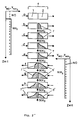
- FIG. 2 shows the ammonia loading of the catalyst zone 4 at different times (corresponding to the process states a to i shown in FIG. 2).
- the catalyst zone 4 consisting of the partial zones 1, 2, 3 is flowed through from left to right by a nitrogen oxide-containing exhaust gas (state a).
- a superstoichiometric amount of ammonia is added to the exhaust gas between sub-zones 1 and 2.
- the excess ammonia not consumed in the reaction with the nitrogen oxides is adsorbed in the catalyst zone (subzone 2).
- An adsorption front 7 is formed, which moves further into the catalyst zone 4 as time progresses (state b and c).
- the decrease in the ammonia load along the catalyst zone 4 at the adsorption front 7 arises from the fact that the ammonia partial pressure and thus also the ammonia load on the catalyst decrease in the flow direction of the exhaust gas by reducing the nitrogen oxides with the ammonia.
- a desorption front 8 is thus formed which, like the adsorption front 7 which continues to exist, migrates through the catalyst zones 4 (states d and e).
- the catalyst zone 4 consists of two subzones of approximately the same size, and the superstoichiometric addition of ammonia takes place between these two subzones.
- FIG. 2 ' this results in an analogous course of the reaction and the catalyst loading as described above for the three-part catalyst zone.
- an ammonia loading maximum moves around the middle of the entire catalyst zone, ie around the location of the ammonia addition.
- larger catalyst loads can be achieved than with a stationary reaction without an ammonia slip occurring.
- a higher degree of NO reduction can be achieved without ammonia breaking through at the ends of the catalyst zone.
- a catalyst zone 4 which has two sub-zones 1 and 2 of approximately the same length lying one behind the other in the flow direction of the exhaust gas.
- the stoichiometric addition of ammonia takes place continuously between these two sub-zones.
- an exhaust gas containing nitrogen oxides flows through the catalyst zone 4 from left to right (state a).
- an adsorption front 7 is also formed, which migrates through the catalyst with increasing time (state b to e).
- the flow direction of the gas is changed.
- a desorption front 8 ' is now formed in subzone 2 and the adsorption front 7' is formed in subzone 1 (states f to i).
- an ammonia loading maximum also migrates around the location of the ammonia addition.
- the ends of the catalyst zone 4 each serve as ammonia buffer zones in the individual process sections.
- the catalyst zone consists of two subzones of the same size, and the ammonia is added between the two subzones.
- the device is used to measure NO conversion and ammonia slip under transient conditions.
- the individual gas components are regulated with the aid of thermal mass flow controllers 9.
- the desired water vapor partial pressure is set with a liquid metering pump 10 and an evaporator 11.
- the heart of the device is a U-shaped reactor 12, which is brought to the desired reaction temperature using electric air heaters 13, 14.
- the direction of flow of the exhaust gas through the catalyst zone in the reactor 12 is changed by means of a four-way valve 15.
- the device has a preheater 16 for nitrogen, air and carbon dioxide, a gas mixer 17 after the reactor 12, an air blower 18 in front of the air heaters 13, 14, taps 19, 20 (Karlsruhe taps), regulating valves 21, 22, 23, 24 , A pressure sensor 25 at the output of the reactor 12, a gas cooler 26 in front of a first analyzer 27 for NO at one output of the device and a second analyzer 28 for NH3, SO2, CO2, H2O and NO2 at another output of the device.
- the individual gas components are analyzed by UV and IR absorption or chemiluminescence.
- Catalyst SCR catalyst containing zeolite Active component of the catalyst: HZSM-5 Number of zones of the catalyst 2, each of the same length NH3 addition: is in the middle of the catalyst zone, between the two sub-zones
- Catalyst mass 50 g
- Catalyst load (0 ° C / 1.013 bar; according to DIN 1343): 2.13 cm3 / g ⁇ s
- Temperature 400 ° C Pressure before entering the reactor: 1.15 bar
- First change in flow direction after 6 min All other changes in flow direction: after every 4 min
- the experimental result shows that the degree of NO reduction is 99% on average and the NH3 slip is less than 2 ppm (measured wet) during the entire test period of 2.5 hours.
- FIG. 3 which has already been explained, shows the flow diagram of a device for carrying out the subsequent embodiment of the method.
- the catalyst zone consists of two subzones of the same size, and the ammonia is added continuously between the two subzones.
- Catalyst SCR catalyst containing zeolite Active component of the catalyst: HZSM-5 Number of zones of the catalyst: 2, each of the same length continuous NH3 addition: in the middle of the catalyst zone, between the two sub-zones
- Catalyst mass 50 g
- Catalyst load (0 ° C, 1.013 bar): 2.13 cm3 / (g ⁇ s)
- the volume in cm3 refers to the standard state according to DIN 1343 at 0 ° C and 1.013 bar.
Landscapes
- Engineering & Computer Science (AREA)
- Chemical & Material Sciences (AREA)
- Environmental & Geological Engineering (AREA)
- General Chemical & Material Sciences (AREA)
- Biomedical Technology (AREA)
- Analytical Chemistry (AREA)
- Health & Medical Sciences (AREA)
- Oil, Petroleum & Natural Gas (AREA)
- Chemical Kinetics & Catalysis (AREA)
- Exhaust Gas Treatment By Means Of Catalyst (AREA)
- Exhaust Gas After Treatment (AREA)
- Catalysts (AREA)
- Treating Waste Gases (AREA)
Claims (4)
- Procédé d'élimination des oxydes d'azote d'un gaz d'échappement par réduction sélective avec de l'ammoniac dans une zone de catalyseur dans laquelle :- le gaz d'échappement et l'ammoniac passent ensemble à travers la zone du catalyseur au cours d'une section déterminée du procédé dans un des sens et au cours d'une section suivante du procédé dans le sens opposé ;- l'ammoniac est amené à la zone du catalyseur seulement dans un certain laps de temps, pendant le passage dans ces sections du procédé en quantité stoechiométrique, par rapport aux oxydes d'azote contenus dans le gaz d'échappement alimenté en même temps ;- pendant le reste du temps de passage de ces sections de procédé de la zone de catalyseur, on n'amène plus d'ammoniac ;- la quantité d'ammoniac amenée en moyenne dans le temps est ajustée aussi bien proportionnellement à la quantité d'oxydes d'azote contenue dans le gaz d'échappement, qu'en fonction du degré de réduction obtenu des oxydes d'azote ;- le sens du courant du gaz d'échappement est inversé, avant que l'ammoniac, considéré dans son sens d'écoulement, ne sorte à l'extrémité de la zone de catalyseur, de même que,- les passages dans les sections de procédé nommées sont souvent réitérés à volonté en alternance,caractérisé en ce que :- l'ammoniac entre dans la zone de catalyseur à un endroit qui est intercalé à la suite, dans le sens du courant du gaz d'échappement, à l'endroit d'entrée du gaz d'échappement, et- on met en oeuvre une zone de catalyseur qui se compose d'au moins deux zones partielles.
- Procédé selon la revendication 1, caractérisé en ce qu'on met en oeuvre une zone de catalyseur, qui comprend dans le sens du courant de gaz d'échappement deux parties de zone de même longueur situées l'une derrière l'autre, entre lesquelles l'ammoniac est amené.
- Procédé selon la revendication 1, caractérisé en ce qu'on met en oeuvre une zone de catalyseur (4), qui comprend dans le sens du courant de gaz d'échappement trois zones partielles (1, 2, 3) situées l'une derrière l'autre, de même que l'ammoniac au cours d'une section déterminée du procédé, est alimenté entre la première et la deuxième zone partielle (1, 2) et au cours d'une section suivante du procédé, avec le sens opposé du courant de gaz d'échappement, il est alimenté entre la deuxième et la troisième zone (2, 3).
- Procédé d'élimination des oxydes d'azote d'un gaz d'échappement par réduction sélective avec de l'ammoniac dans une zone de catalyseurs, dans laquelle :- le gaz d'échappement et l'ammoniac passent ensemble à travers la zone de catalyseurs au cours d'une section déterminée du procédé dans un des sens et au cours d'une section suivante du procédé dans le sens inverse ;- la quantité d'ammoniac amenée en moyenne dans le temps est ajustée aussi bien proportionnellement à la quantité d'oxydes d'azote contenue dans le gaz d'échappement qu'en fonction du degré de réduction obtenu des oxydes d'azote ;- le sens du courant du gaz d'échappement est inversé, avant que l'ammoniac, considéré dans son sens d'écoulement, ne sorte à l'extrémité de la zone de catalyseur, de même que,- les sections de procédé citées sont souvent répétées à volonté,caractérisé en ce que :- la zone de catalyseur se compose dans le sens de courant du gaz d'échappement de deux zones partielles sensiblement de même longueur, situées l'une derrière l'autre, entre lesquelles l'ammoniac est amené en continu à la zone de catalyseur en quantité stoechiométrique, par rapport aux oxydes d'azote contenus dans le gaz d'échappement alimenté en même temps.
Applications Claiming Priority (2)
| Application Number | Priority Date | Filing Date | Title |
|---|---|---|---|
| DE4102075 | 1991-01-24 | ||
| DE4102075A DE4102075A1 (de) | 1991-01-24 | 1991-01-24 | Verfahren zum entfernen von stickstoffoxiden aus einem abgas |
Publications (2)
| Publication Number | Publication Date |
|---|---|
| EP0496096A1 EP0496096A1 (fr) | 1992-07-29 |
| EP0496096B1 true EP0496096B1 (fr) | 1995-06-21 |
Family
ID=6423631
Family Applications (1)
| Application Number | Title | Priority Date | Filing Date |
|---|---|---|---|
| EP91122044A Expired - Lifetime EP0496096B1 (fr) | 1991-01-24 | 1992-01-01 | Procédé d'élimination des oxydes d'azote d'un gaz d'échappement |
Country Status (3)
| Country | Link |
|---|---|
| EP (1) | EP0496096B1 (fr) |
| AT (1) | ATE123971T1 (fr) |
| DE (2) | DE4102075A1 (fr) |
Families Citing this family (2)
| Publication number | Priority date | Publication date | Assignee | Title |
|---|---|---|---|---|
| JP4087914B2 (ja) * | 1996-07-25 | 2008-05-21 | 日本碍子株式会社 | 脱硝システム及び脱硝方法 |
| WO2023287926A1 (fr) * | 2021-07-13 | 2023-01-19 | Pts Power Inc. | Système et procédé d'utilisation d'énergie thermique de trajet de gaz d'échappement |
Family Cites Families (4)
| Publication number | Priority date | Publication date | Assignee | Title |
|---|---|---|---|---|
| DE3505354A1 (de) * | 1984-04-05 | 1985-10-17 | Linde Ag, 6200 Wiesbaden | Verfahren und vorrichtung zur entfernung unerwuenschter gasfoermiger bestandteile aus einem rauchgas |
| DE3637871C1 (de) * | 1985-10-17 | 1988-03-24 | Kernforschungsz Karlsruhe | Verfahren und Vorrichtung zur katalytischen Reduktion von Schadstoffen in Rauchgas |
| DE3744388A1 (de) * | 1987-12-29 | 1989-07-13 | Basf Ag | Verfahren zum entfernen von stickoxiden aus abgasen |
| DE3805791A1 (de) * | 1988-02-24 | 1989-08-31 | Kraftanlagen Ag | Verfahren und anlage zur entstickung der abgase von feuerungsanlagen |
-
1991
- 1991-01-24 DE DE4102075A patent/DE4102075A1/de active Granted
-
1992
- 1992-01-01 EP EP91122044A patent/EP0496096B1/fr not_active Expired - Lifetime
- 1992-01-01 AT AT91122044T patent/ATE123971T1/de not_active IP Right Cessation
- 1992-01-01 DE DE59202564T patent/DE59202564D1/de not_active Expired - Fee Related
Also Published As
| Publication number | Publication date |
|---|---|
| EP0496096A1 (fr) | 1992-07-29 |
| DE59202564D1 (de) | 1995-07-27 |
| ATE123971T1 (de) | 1995-07-15 |
| DE4102075C2 (fr) | 1993-03-25 |
| DE4102075A1 (de) | 1992-07-30 |
Similar Documents
| Publication | Publication Date | Title |
|---|---|---|
| DE69738296T2 (de) | Methode zur entstickung von abgas | |
| DE3232543C2 (de) | Verfahren zum Entfernen von Schwefel- und Stickstoffoxiden aus einem Abgas | |
| EP3095505B1 (fr) | Procédé et installation pour le nettoyage de gaz d'échappement chargés en oxydes d'azote | |
| DE2754932C2 (de) | Verfahren zum Entfernen von Stickstoffoxiden aus einem Gas | |
| DE2459913C2 (de) | Verfahren zur Entfernung von SO↓x↓ und NO↓x↓ aus Abgasen | |
| DE69736093T2 (de) | Entfernung von Stickstoffoxiden und Schwefeloxiden aus Verbrennungsgasströmen | |
| EP0232731B1 (fr) | Procédé et dispositif de purification de gaz, en particulier pour désulfurer et désazoturer des gaz de fumée | |
| EP0257024B1 (fr) | Procede d'elimination selective d'oxydes nitriques contenus dans des gaz d'echappement | |
| WO2020215115A1 (fr) | Récipient et procédé de chargement d'un agent d'adsorption et/ou d'absorption avec de l'ammoniac | |
| EP0232452B1 (fr) | Procédé pour éliminer des oxydes d'azote de gaz fumée | |
| DE69505959T2 (de) | Behandlung von abgas eines fliessbett-druckreaktionssystems | |
| DE2259763C3 (de) | Verfahren zur Reinigung von Stickstoffoxide enthaltenden Gasen und Vorrichtung zu dessen Durchführung | |
| DE3805791A1 (de) | Verfahren und anlage zur entstickung der abgase von feuerungsanlagen | |
| DE69410853T2 (de) | Behandlung von Abgas eines Verbrennungsofens | |
| DE3039477A1 (de) | Verfahren zur entfernung von schwefeloxiden und stickstoffoxiden aus abgasen sowie vorrichtung zur durchfuehrung dieses verfahrens | |
| DE4204603C2 (de) | Vorrichtung zur mehrstufigen, katalytischen Verbrennung von stickstoffhaltigen Gasen | |
| DE2737117C3 (fr) | ||
| DD231742A5 (de) | Verfahren und vorrichtung zur entfernung unerwuenschter gasfoermiger bestandteile aus einem rauchgas | |
| DE3505354A1 (de) | Verfahren und vorrichtung zur entfernung unerwuenschter gasfoermiger bestandteile aus einem rauchgas | |
| DE4102075C2 (fr) | ||
| EP0328777B1 (fr) | Procédé d'élemination d'oxydes d'azote de gaz d'échappement | |
| DD270538A5 (de) | Verfahren zum regenieren von mit kohlendioxid und kohlenoxisulfid beladenen waschloesungsstroemen | |
| EP0161470B1 (fr) | Procédé et dispositif pour éliminer des substances gazeuses indésirables d'un gaz de fumée | |
| DE3232544A1 (de) | Verfahren zum entfernen von schwefel- und stickstoffoxiden aus einem abgas | |
| DE2919812A1 (de) | Verfahren und vorrichtung zur behandlung von abgasen |
Legal Events
| Date | Code | Title | Description |
|---|---|---|---|
| PUAI | Public reference made under article 153(3) epc to a published international application that has entered the european phase |
Free format text: ORIGINAL CODE: 0009012 |
|
| AK | Designated contracting states |
Kind code of ref document: A1 Designated state(s): AT BE CH DE DK ES FR GB GR IT LI LU MC NL PT SE |
|
| 17P | Request for examination filed |
Effective date: 19921016 |
|
| 17Q | First examination report despatched |
Effective date: 19940119 |
|
| GRAA | (expected) grant |
Free format text: ORIGINAL CODE: 0009210 |
|
| AK | Designated contracting states |
Kind code of ref document: B1 Designated state(s): AT BE CH DE DK ES FR GB GR IT LI LU MC NL PT SE |
|
| PG25 | Lapsed in a contracting state [announced via postgrant information from national office to epo] |
Ref country code: IT Free format text: LAPSE BECAUSE OF FAILURE TO SUBMIT A TRANSLATION OF THE DESCRIPTION OR TO PAY THE FEE WITHIN THE PRE;WARNING: LAPSES OF ITALIAN PATENTS WITH EFFECTIVE DATE BEFORE 2007 MAY HAVE OCCURRED AT ANY TIME BEFORE 2007. THE CORRECT EFFECTIVE DATE MAY BE DIFFERENT FROM THE ONE RECORDED.SCRIBED TIME-LIMIT Effective date: 19950621 Ref country code: GB Effective date: 19950621 Ref country code: GR Free format text: LAPSE BECAUSE OF FAILURE TO SUBMIT A TRANSLATION OF THE DESCRIPTION OR TO PAY THE FEE WITHIN THE PRESCRIBED TIME-LIMIT Effective date: 19950621 Ref country code: MC Free format text: LAPSE BECAUSE OF NON-PAYMENT OF DUE FEES Effective date: 19950621 Ref country code: NL Free format text: LAPSE BECAUSE OF FAILURE TO SUBMIT A TRANSLATION OF THE DESCRIPTION OR TO PAY THE FEE WITHIN THE PRESCRIBED TIME-LIMIT Effective date: 19950621 Ref country code: ES Free format text: THE PATENT HAS BEEN ANNULLED BY A DECISION OF A NATIONAL AUTHORITY Effective date: 19950621 Ref country code: FR Effective date: 19950621 Ref country code: BE Effective date: 19950621 Ref country code: DK Effective date: 19950621 |
|
| REF | Corresponds to: |
Ref document number: 123971 Country of ref document: AT Date of ref document: 19950715 Kind code of ref document: T |
|
| REF | Corresponds to: |
Ref document number: 59202564 Country of ref document: DE Date of ref document: 19950727 |
|
| PG25 | Lapsed in a contracting state [announced via postgrant information from national office to epo] |
Ref country code: SE Effective date: 19950921 Ref country code: PT Effective date: 19950921 |
|
| EN | Fr: translation not filed | ||
| PG25 | Lapsed in a contracting state [announced via postgrant information from national office to epo] |
Ref country code: AT Effective date: 19960101 |
|
| NLV1 | Nl: lapsed or annulled due to failure to fulfill the requirements of art. 29p and 29m of the patents act | ||
| GBV | Gb: ep patent (uk) treated as always having been void in accordance with gb section 77(7)/1977 [no translation filed] |
Effective date: 19950621 |
|
| PG25 | Lapsed in a contracting state [announced via postgrant information from national office to epo] |
Ref country code: LU Free format text: LAPSE BECAUSE OF NON-PAYMENT OF DUE FEES Effective date: 19960131 Ref country code: LI Effective date: 19960131 Ref country code: CH Effective date: 19960131 |
|
| PLBE | No opposition filed within time limit |
Free format text: ORIGINAL CODE: 0009261 |
|
| STAA | Information on the status of an ep patent application or granted ep patent |
Free format text: STATUS: NO OPPOSITION FILED WITHIN TIME LIMIT |
|
| 26N | No opposition filed | ||
| REG | Reference to a national code |
Ref country code: CH Ref legal event code: PL |
|
| PG25 | Lapsed in a contracting state [announced via postgrant information from national office to epo] |
Ref country code: DE Effective date: 19961001 |