EP0496104A1 - Soupape mélangeur sanitaire - Google Patents
Soupape mélangeur sanitaire Download PDFInfo
- Publication number
- EP0496104A1 EP0496104A1 EP91122088A EP91122088A EP0496104A1 EP 0496104 A1 EP0496104 A1 EP 0496104A1 EP 91122088 A EP91122088 A EP 91122088A EP 91122088 A EP91122088 A EP 91122088A EP 0496104 A1 EP0496104 A1 EP 0496104A1
- Authority
- EP
- European Patent Office
- Prior art keywords
- hollow piston
- membrane
- mixer tap
- electrically operated
- tap according
- Prior art date
- Legal status (The legal status is an assumption and is not a legal conclusion. Google has not performed a legal analysis and makes no representation as to the accuracy of the status listed.)
- Granted
Links
- XLYOFNOQVPJJNP-UHFFFAOYSA-N water Substances O XLYOFNOQVPJJNP-UHFFFAOYSA-N 0.000 claims abstract description 49
- 239000012528 membrane Substances 0.000 claims description 40
- 239000011324 bead Substances 0.000 claims description 4
- 240000007124 Brassica oleracea Species 0.000 claims description 2
- 235000003899 Brassica oleracea var acephala Nutrition 0.000 claims description 2
- 235000011301 Brassica oleracea var capitata Nutrition 0.000 claims description 2
- 235000001169 Brassica oleracea var oleracea Nutrition 0.000 claims description 2
- 239000007787 solid Substances 0.000 claims 1
- 238000010276 construction Methods 0.000 abstract description 2
- 210000004379 membrane Anatomy 0.000 description 25
- 238000013459 approach Methods 0.000 description 5
- 230000003287 optical effect Effects 0.000 description 3
- 238000001514 detection method Methods 0.000 description 1
- 239000013013 elastic material Substances 0.000 description 1
- 238000000034 method Methods 0.000 description 1
- 230000000284 resting effect Effects 0.000 description 1
- 238000007789 sealing Methods 0.000 description 1
- 238000000926 separation method Methods 0.000 description 1
- 230000007704 transition Effects 0.000 description 1
Images



Classifications
-
- E—FIXED CONSTRUCTIONS
- E03—WATER SUPPLY; SEWERAGE
- E03C—DOMESTIC PLUMBING INSTALLATIONS FOR FRESH WATER OR WASTE WATER; SINKS
- E03C1/00—Domestic plumbing installations for fresh water or waste water; Sinks
- E03C1/02—Plumbing installations for fresh water
- E03C1/05—Arrangements of devices on wash-basins, baths, sinks, or the like for remote control of taps
- E03C1/055—Electrical control devices, e.g. with push buttons, control panels or the like
- E03C1/057—Electrical control devices, e.g. with push buttons, control panels or the like touchless, i.e. using sensors
-
- G—PHYSICS
- G05—CONTROLLING; REGULATING
- G05D—SYSTEMS FOR CONTROLLING OR REGULATING NON-ELECTRIC VARIABLES
- G05D23/00—Control of temperature
- G05D23/01—Control of temperature without auxiliary power
- G05D23/13—Control of temperature without auxiliary power by varying the mixing ratio of two fluids having different temperatures
- G05D23/1393—Control of temperature without auxiliary power by varying the mixing ratio of two fluids having different temperatures characterised by the use of electric means
-
- Y—GENERAL TAGGING OF NEW TECHNOLOGICAL DEVELOPMENTS; GENERAL TAGGING OF CROSS-SECTIONAL TECHNOLOGIES SPANNING OVER SEVERAL SECTIONS OF THE IPC; TECHNICAL SUBJECTS COVERED BY FORMER USPC CROSS-REFERENCE ART COLLECTIONS [XRACs] AND DIGESTS
- Y10—TECHNICAL SUBJECTS COVERED BY FORMER USPC
- Y10T—TECHNICAL SUBJECTS COVERED BY FORMER US CLASSIFICATION
- Y10T137/00—Fluid handling
- Y10T137/8593—Systems
- Y10T137/87571—Multiple inlet with single outlet
- Y10T137/87676—With flow control
- Y10T137/87684—Valve in each inlet
- Y10T137/87692—With common valve operator
-
- Y—GENERAL TAGGING OF NEW TECHNOLOGICAL DEVELOPMENTS; GENERAL TAGGING OF CROSS-SECTIONAL TECHNOLOGIES SPANNING OVER SEVERAL SECTIONS OF THE IPC; TECHNICAL SUBJECTS COVERED BY FORMER USPC CROSS-REFERENCE ART COLLECTIONS [XRACs] AND DIGESTS
- Y10—TECHNICAL SUBJECTS COVERED BY FORMER USPC
- Y10T—TECHNICAL SUBJECTS COVERED BY FORMER US CLASSIFICATION
- Y10T137/00—Fluid handling
- Y10T137/8593—Systems
- Y10T137/87917—Flow path with serial valves and/or closures
- Y10T137/88022—One valve head provides seat for other head
- Y10T137/8803—Also carries head of other valve
Definitions
- the invention relates to a sanitary mixer tap with a housing, with an electrically operated valve, the closing elements of which control the outflowing mixed water, with a control element arranged in a chamber of the housing, which determines the ratio of cold and hot water in the outflowing mixed water, and with an outlet .
- control element determining the mixed water temperature and the electrically operated valve (generally a purely shut-off valve) were spatially separated from one another.
- the object of the present invention is to design a sanitary mixer tap of the type mentioned at the outset in such a way that at least the control element and the electrically operated valve require less space and the mixer tap can thus be given a more pleasing appearance.
- At least the closing elements of the electrically operated valve are thus accommodated within the control element itself, which is designed as a hollow piston for this purpose.
- a water flow must be selected, in which the path of the mixed water in the direction of the outlet of the fitting leads at least partially through the interior of the hollow piston.
- the closing elements of the electrically operated valve take part in all movements of the hollow piston.
- a cylindrical apron is expediently formed on the hollow piston, on which an actuating handle can be fastened. In general, it is still common Even with electrically operated or non-contact controlled sanitary fittings, the temperature is set manually.
- electrically operated valves comprise a solenoid. According to a special feature of the invention, this can be arranged in the space surrounded by the skirt of the hollow piston.
- the structure on the outer circumference of the hollow piston which determines the mixing ratio of the outflowing water, can in particular comprise a groove which guides the mixed water along the outside of the hollow piston. After entering the housing chamber in which the hollow piston moves, the water path first leads along the outside of the hollow piston before the mixed water is then conducted into the interior of the hollow piston and to the closing elements of the electrically operated valve arranged there.
- the control element is very often designed as a rotary piston. Then the configuration is recommended in which the groove is helically guided along the outer circumference of the hollow piston at an angle with respect to the axis and in which the center points of the mouth openings of the flow paths for cold and hot water into the housing chamber lie on a straight line that is to the axis of rotation of the hollow piston is parallel.
- the "oblique" groove cuts the two mouth openings of the flow paths for cold and hot water differently depending on the rotational position at. This means that depending on the rotational position, different amounts of cold and hot water can flow from the corresponding flow paths into the groove and from there into the interior of the hollow piston.
- pilot-operated valves are used as electrically operated valves for energy reasons.
- a closing element these comprise an elastic membrane, which can move back and forth between an open and a closed position under the influence of the pressures prevailing on their two sides, a closing body which can be moved by the magnetic coil opening and closing a pilot opening reducing the pressures on both Affected sides of the membrane.
- Such a pilot-controlled valve can be used for the purposes of the invention in particular when the closing body and pilot opening are arranged away from the membrane in the vicinity of the magnetic coil, a first channel being led from the pilot opening through a massive area of the hollow piston into a room, in which the pressure prevailing on one side of the membrane is present, and from the space which, after the closing body has been lifted off the pilot opening, comes into contact with the first channel, a second channel is led into a space through a massive region of the hollow piston which is the pressure on the other side of the membrane. Due to the spatial separation of the elastic membrane and closing body and the pilot opening, the spatial conditions on or in the hollow piston can be better utilized, the two channels mentioned serving to convey the pressures prevailing on both sides of the membrane.
- the contact body is preferably part of a cage holding the membrane, each having a support ring at the axial ends, which cooperates with a radial bead on the corresponding axial end of the membrane, the two support rings being connected to the contact body via ribs.
- the closing elements of the electrically operated valve are combined to form a unit which can be pushed into the interior of the hollow piston as a whole. This unit can also be replaced as a whole if necessary.
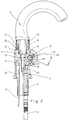
- the non-contact controlled sanitary fitting shown can be divided into five main components: A swivel spout 3 is attached to a central main housing 1, to which a base part 2 is attached at the bottom. Inlet channels 4 for hot and cold water (one indicated by dashed lines in FIG. 2) penetrate the base part 2. Flexible water supply hoses 5 are screwed into these from below.
- two handle-like extensions 6 and 7 are attached to the main housing 1.
- the left handle-like extension 6 has only the external appearance, but not the function of a handle. It is only used to hold the electronic components of the non-contact valve. 1 and 3 show the optical entry and exit window 8 for the infrared light used to detect a user. The window 8 is colored dark, so that its function as an optical window and the transmitter diode 9 behind it and the receiver diode 10 cannot be seen (see the section in FIG. 3).
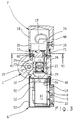
- FIG. 3 it can be seen how the electronics 11 are accommodated inside the handle-like extension 6, which is supplied with the supply voltage via a cable 12 on the one hand and which is connected to a solenoid valve 14 via a further cable 13 in a manner yet to be described which controls the flow of water.
- the cable 12 is made via an axially parallel bore 15 in the main housing 1 or the base part 2 and an oblique bore 16 in the main housing 1 from the sanitary fitting.
- the right handle-like approach 7 is not only "handle-like" in the illustrated embodiment, so it not only sees a conventional sanitary fitting handle but actually has this function. It can be rotated about its horizontal axis to adjust the temperature of the mixed water flowing out of the sanitary fitting. In the case of a sanitary fitting which only releases water at a single temperature, the attachment 7 would also only be "similar" to the handle, ie it would not really perform the function of a handle, but would only pretend the presence of such a handle.
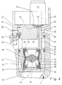
- FIGS. 4 and 5 have a larger scale than FIGS. 1 to 3.
- the cup-shaped outer housing 18 of the handle-like extension 7 is omitted in FIGS. 4 and 5 for the sake of clarity. It is fastened with a screw 19 to a cylindrical skirt 20 of the grater 17, as can be seen in FIG. 3.
- the outer housing 18 is rotated, the entire grater 17 is taken along, which changes the mixing ratio of cold and hot water in a manner to be described.
- the grater 17 is a one-piece molded part which projects into a cylindrical chamber 21 of the main housing 1 at the end facing away from the apron 20. Bores 22, 23 (see also FIG. 5), which pass obliquely through the main housing 1 and which communicate with the bores 4 in the base part 2 and through which cold and hot water can thus reach the cylindrical chamber 21, open into this chamber 21. Axially offset from the bores 22 and 23, another bore 24 of the main housing 1 opens into the cylindrical chamber 21, which is connected to a vertical bore 25 leading to the outlet 3. This can be seen in particular in FIG. 3. If the inner end of the grater 17 were not inserted into the cylindrical chamber 21, the water flowing in via the hoses 5, the channels 4, 22 and 23 into the cylindrical chamber 21 of the main housing 1 could directly flow through the bores 24 and 25 to the outlet 3 stream.
- the setting of the mixing ratio of cold and hot water is done by an essentially cylindrical head 26 of the grater 17, in which an oblique groove 27 is incorporated.
- the groove 27 cuts channels 22 and 23 in the main housing differ depending on the rotary position.
- FIG. 5 shows the position in which the same proportions of cold and hot water are obtained because the channels 22 and 23 both open to the same extent, namely half, into the groove 27. Water can therefore flow into the groove 27 from the channels 22 and 23.
- the groove 27 guides the mixing water into a recess 28 on the outer circumference of the head 26 of the grater 17, from where it can reach the end of the grater 17.
- An elastic cushion 79 is embedded in the lower region of the lateral surface of the grater head 26. If the grater 17 is turned to the full cold position, the cushion 79 lies over the mouth of the bore 22 supplying the hot water and closes it tightly. This prevents hot water losses.
- the further path of the mixed water which has reached the open end face of the grater 17 to the channel 24 and thus to the outlet 3 leads via the interior of the hollow head 26 of the grater 17, in which a pilot-controlled valve 29 is accommodated, and via a radial bore 44 in the grater 17 and an annular space 78, which lies between the wall of the chamber 21 and a reduced-diameter area of the grater 17.
- the annular space 78 is delimited in the axial direction by two O-rings 56 and 57, which are arranged in grooves on the outer surface of the grater 17.
- the pilot-controlled valve 29 comprises a membrane 30 made of elastic material and a cage as closing elements 31 made of rigid plastic, with which the membrane 30 cooperates. Although this is shown in one piece in the drawing, it can also be constructed in several parts.
- the elastic membrane 30 has the shape of two truncated cones, which are arranged in opposite directions, with beads 32, 33 projecting radially inwards on the axially opposite ends.
- the cage 31 comprises a central contact body 34 and at both axial ends a support ring 35 and 36, respectively, which cooperates with the bead 32, 33 of the elastic membrane 30 located there.
- the contact body 34 of the cage 31 is connected to the support rings 35, 36 via ribs 37 to form a unit.
- Cage 31 and membrane 30 tied thereon lie against a step in the interior of the grater and are releasably secured at the outer end by an insert ring 46 and a snap ring 47.
- the elastic membrane 30 is shaped such that it normally rests against the outside of the contact body 34 of the cage 31, ie without pressure from water from inside or outside. This is the closed state of the pilot-controlled valve 29, since then the water path through the interior of the grater 17 to the channel 24 is blocked by the contact body 34 and the membrane 29.
- the membrane 29 can move from the closed position shown into an open position by lifting off from the contact body 34 in the central region and resting against the wall of the cylindrical chamber 21 of the main housing 1. An annular space between the membrane 29 and the contact body 24 is released for flow.
- the inner space of the membrane 29 below the contact body 34 is connected to the outer space by a small radial compensating bore 38. This in turn communicates via an axially parallel channel 39 with a recess 40 on the outer end face of the grater 17, which is located radially inside the skirt 20.
- the recess 40 is covered by the underside of the magnet coil 14 and sealed by an O-ring 45.
- a valve seat 41 is formed, which cooperates with a closing body 42.
- the closing body 42 normally closes the valve seat 41 and thus the access to an axially parallel channel 43, which leads to the radial bore 44 in the grater 17 and thus to the channel 24 in the main housing 1.
- the units held or formed by the handle-like extensions 6 and 7 are preassembled.
- the housing 52 has a thread at its open end, into which a ring 49 is screwed.
- Two screws 50, 51 extend transversely through the main housing 1 and are screwed with their threaded end into threaded holes in the ring 49.
- the heads of the screws 50, 51 lie against countersinking in the right side surface of the main housing 1 in FIG. 1.
- the left handle-like extension 6 is thus attached to the main housing 1.
- the cable 12 is of course still run through the channels 15 and 16; the cable 13 is led through a channel 53 which completely penetrates the main housing 1 (cf. also FIG. 2) to the other side surface of the main housing 1.
- a cylindrical collar 54 at the inner end of the housing 52 protrudes into a groove on the left side surface of the main housing 1 in FIG. 1. This results in a visually pleasing transition between the handle-like extension 6 and the main housing 1.
- the grater 17 is provided with a groove 58 at that axial point at which the right-hand side face of the main housing 1 comes to rest in the installed state.
- a U-shaped fastening part 59 is inserted into this groove 58 from the side. This is screwed with three screws 60, 61 and 62 to the right side surface of the main housing 1 in FIG. 1.
- One of these screws, namely screw 60, is shown in FIGS.
- the angle through which the grater 17 can be rotated to adjust the temperature of the outflowing mixed water can be set in the following way: Immediately adjacent to the outside of the groove 58 (in 4 thus above this), a further recess 65 is provided in the outer contour of the grater 17, but this has a larger diameter than the groove 58 and is not completely guided around the circumference of the grater 17. Rather, as can be seen in FIG. 6, a dovetail-shaped extension 66 projects radially outward from the "core" 67 of the grater 17. This dovetail-shaped extension 66 limits the rotatability of the grater 17 in FIG. 6 clockwise by coming into contact with the head of the screw 60.
- An arcuate elongated hole 68 penetrates the wall between the annular shoulder, which is formed by the recess 65 against the portion of the grater 17 that carries the apron 20, and the outer end wall of the grater 17, which is surrounded by the apron 20, onto which the magnet coil 14 is also placed is.
- a screw 69 is guided through this slot 68 from the outside and holds a stop piece 70 on the aforementioned annular shoulder of the recess 65.
- the stop piece 70 runs radially from the "core" 67 of the grater 17 to the outer circumference of the annular shoulder formed by the recess 65. It limits the rotatability of the grater 17 counterclockwise by coming to bear against the head of the screw 60.
- the total angle of rotation through which the grater 17 can be seen is determined by the variable position of the stop piece 70 in the arcuate elongated hole 68.
- the head of the screw 19 in the handle 18 is covered with a window 48, the appearance of which corresponds to the window 8 in the handle-like attachment 6 on the left in FIG. Externally, as can be seen in FIG. 1, there is a completely symmetrical appearance.
- the main housing 1 is fastened to the base part 2 by a central screw 72 (FIG. 2), the head of which lies in the upper region in the bore 25 already mentioned, which leads the mixed water flowing from the cylindrical chamber 21 to the outlet 3.
- the downward waterway is blocked in FIG. 2 by a sealing ring 73, which is arranged between the head of the screw 72 and the ring shoulder of the bore 25 below it.
- a mounting piece 74 is screwed into the latter from above.
- the attachment piece 74 has a somewhat larger diameter in the upper region and here lies on the inner wall of the outlet 3 via O-rings. This is pushed over the mounting piece 74 to close to the upper end face of the main housing 1.
- a U-shaped fastening part 75 lies between the inner wall of the outlet 3 and the region of the fastening socket 74 which is reduced in diameter.
- the outlet 3 is fixed to it by means of a screw 76.
- the fastening part 75 bears with an axially extending projection 77 on an annular step which has the same diameter Connects wider area of the mounting piece 74 with the smaller diameter area.
- the outlet 3 is fixed in the axial direction.
- the axial projection 77 also acts as a limitation for the angle of rotation through which the outlet 3 can measure in relation to the main housing 1.
- the exemplary embodiment described above concerned a contactlessly controlled, electrically operated mixer tap with a certain division of the various components into two handle-like approaches. Contactlessness and the division described are not necessary features of the invention.
Landscapes
- Engineering & Computer Science (AREA)
- Physics & Mathematics (AREA)
- General Physics & Mathematics (AREA)
- Automation & Control Theory (AREA)
- Health & Medical Sciences (AREA)
- Life Sciences & Earth Sciences (AREA)
- Hydrology & Water Resources (AREA)
- Public Health (AREA)
- Water Supply & Treatment (AREA)
- Multiple-Way Valves (AREA)
- Domestic Plumbing Installations (AREA)
- Battery Electrode And Active Subsutance (AREA)
Applications Claiming Priority (2)
| Application Number | Priority Date | Filing Date | Title |
|---|---|---|---|
| DE4102135A DE4102135C2 (de) | 1991-01-25 | 1991-01-25 | Sanitäre Mischarmatur |
| DE4102135 | 1991-01-25 |
Publications (2)
| Publication Number | Publication Date |
|---|---|
| EP0496104A1 true EP0496104A1 (fr) | 1992-07-29 |
| EP0496104B1 EP0496104B1 (fr) | 1994-07-27 |
Family
ID=6423662
Family Applications (1)
| Application Number | Title | Priority Date | Filing Date |
|---|---|---|---|
| EP91122088A Expired - Lifetime EP0496104B1 (fr) | 1991-01-25 | 1991-12-22 | Soupape mélangeur sanitaire |
Country Status (6)
| Country | Link |
|---|---|
| US (1) | US5156187A (fr) |
| EP (1) | EP0496104B1 (fr) |
| JP (1) | JP3280053B2 (fr) |
| AT (1) | ATE109260T1 (fr) |
| DE (1) | DE4102135C2 (fr) |
| ES (1) | ES2060279T3 (fr) |
Cited By (1)
| Publication number | Priority date | Publication date | Assignee | Title |
|---|---|---|---|---|
| EP1700958A1 (fr) * | 2005-03-11 | 2006-09-13 | Hansa Metallwerke Ag | Robinet sanitaire avec un corps plaçable au-dessous d'un lavabo ou évier, ledit corps contenant au moins un moyen de fonction à opérer électriquement |
Families Citing this family (7)
| Publication number | Priority date | Publication date | Assignee | Title |
|---|---|---|---|---|
| SE467890B (sv) * | 1991-02-01 | 1992-09-28 | Mattsson Ab F M | Reglerenhet till blandarventil med en tryckberoende kolvslid koaxiellt roerlig i foerhaallande till en temperaturberoende reglerventilkaegla |
| DE4106540C2 (de) * | 1991-03-01 | 1994-09-29 | Hansa Metallwerke Ag | Sanitärarmatur |
| IT1262712B (it) * | 1993-03-18 | 1996-07-04 | Sol Spa | Perfezionamenti ai rubinetti miscelatori a comando elettronico |
| DE4431127C2 (de) * | 1994-09-01 | 2001-02-15 | Hansgrohe Ag | Sanitärventil mit einem Magnetventil |
| DE10316372B3 (de) | 2003-04-10 | 2004-12-02 | Hansa Metallwerke Ag | Sanitäres Mischventil |
| DE102007035969A1 (de) | 2007-07-30 | 2009-02-05 | Hidde, Axel R., Dr. | Ventilbaukasten mit Keramikventil |
| US20160208948A1 (en) * | 2015-01-19 | 2016-07-21 | Moen Incorporated | Electronic plumbing fixture fitting with electronic valve having operation modes |
Citations (4)
| Publication number | Priority date | Publication date | Assignee | Title |
|---|---|---|---|---|
| AU7326187A (en) * | 1987-05-21 | 1988-11-24 | Pasquale Ferrante | Tap for the delivery of liquids for the conversion from automatic to manual |
| DE3800557A1 (de) * | 1988-01-12 | 1989-07-20 | Karl Ludwig Maisbacher | Schutz von indirekt gesteuerten membranventilen vor funktionsunfaehigkeit durch verschmutzt durchstroemende medien |
| JPH01203530A (ja) * | 1988-02-06 | 1989-08-16 | Toto Ltd | 自動水栓 |
| EP0384006A1 (fr) * | 1989-02-24 | 1990-08-29 | Cosmos Entwicklungs- Und Forschungsanstalt | Armature sanitaire pour robinets |
Family Cites Families (13)
| Publication number | Priority date | Publication date | Assignee | Title |
|---|---|---|---|---|
| GB190603196A (en) * | 1906-02-09 | 1906-11-22 | G & W G Gummer Ltd | Improvements in Bath Valves and the like Water Fittings. |
| US2766774A (en) * | 1954-04-30 | 1956-10-16 | Rene H J Mornard | Faucet assembly |
| US3118646A (en) * | 1961-01-09 | 1964-01-21 | Dura Bond Bearing Company | Pilot operated valve |
| US3145967A (en) * | 1962-04-27 | 1964-08-25 | Lawrence H Gardner | Elastic sleeve valve |
| US3245430A (en) * | 1963-04-25 | 1966-04-12 | Arrowhead Brass Products | Combination proportioning, diverter, and shut-off valve |
| US3420272A (en) * | 1966-12-05 | 1969-01-07 | Standard Screw | Mixing valve |
| US3472283A (en) * | 1967-05-29 | 1969-10-14 | Young Stephen A | Single-lever operated mixing valve |
| US3870080A (en) * | 1974-01-14 | 1975-03-11 | Hermann H Landwehr | Volume and temperature regulating faucet |
| DE2619465A1 (de) * | 1976-05-03 | 1977-11-24 | Eberspaecher J | Mischbatterie |
| US4741363A (en) * | 1986-10-29 | 1988-05-03 | Hydrotek Corporation | Fluid faucet |
| DE3818342A1 (de) * | 1988-05-30 | 1989-12-07 | Hansa Metallwerke Ag | Beruehrungslos gesteuerte sanitaerarmatur |
| DE3822830A1 (de) * | 1988-07-06 | 1990-01-11 | Mueller A & K Gmbh Co Kg | Eigenmediumbetaetigtes, durch ein bistabiles magnetventil servogesteuertes ventil fuer fluessige medien |
| US5050641A (en) * | 1990-05-08 | 1991-09-24 | Shwu Fen Sheu | Photoelectric single handle faucet |
-
1991
- 1991-01-25 DE DE4102135A patent/DE4102135C2/de not_active Expired - Fee Related
- 1991-12-22 AT AT91122088T patent/ATE109260T1/de not_active IP Right Cessation
- 1991-12-22 ES ES91122088T patent/ES2060279T3/es not_active Expired - Lifetime
- 1991-12-22 EP EP91122088A patent/EP0496104B1/fr not_active Expired - Lifetime
-
1992
- 1992-01-22 US US07/823,774 patent/US5156187A/en not_active Expired - Fee Related
- 1992-01-27 JP JP01208392A patent/JP3280053B2/ja not_active Expired - Fee Related
Patent Citations (4)
| Publication number | Priority date | Publication date | Assignee | Title |
|---|---|---|---|---|
| AU7326187A (en) * | 1987-05-21 | 1988-11-24 | Pasquale Ferrante | Tap for the delivery of liquids for the conversion from automatic to manual |
| DE3800557A1 (de) * | 1988-01-12 | 1989-07-20 | Karl Ludwig Maisbacher | Schutz von indirekt gesteuerten membranventilen vor funktionsunfaehigkeit durch verschmutzt durchstroemende medien |
| JPH01203530A (ja) * | 1988-02-06 | 1989-08-16 | Toto Ltd | 自動水栓 |
| EP0384006A1 (fr) * | 1989-02-24 | 1990-08-29 | Cosmos Entwicklungs- Und Forschungsanstalt | Armature sanitaire pour robinets |
Cited By (1)
| Publication number | Priority date | Publication date | Assignee | Title |
|---|---|---|---|---|
| EP1700958A1 (fr) * | 2005-03-11 | 2006-09-13 | Hansa Metallwerke Ag | Robinet sanitaire avec un corps plaçable au-dessous d'un lavabo ou évier, ledit corps contenant au moins un moyen de fonction à opérer électriquement |
Also Published As
| Publication number | Publication date |
|---|---|
| JPH04302624A (ja) | 1992-10-26 |
| ES2060279T3 (es) | 1994-11-16 |
| ATE109260T1 (de) | 1994-08-15 |
| US5156187A (en) | 1992-10-20 |
| DE4102135C2 (de) | 1995-06-22 |
| JP3280053B2 (ja) | 2002-04-30 |
| EP0496104B1 (fr) | 1994-07-27 |
| DE4102135A1 (de) | 1992-07-30 |
Similar Documents
| Publication | Publication Date | Title |
|---|---|---|
| DE69110630T2 (de) | Ausgabevorrichtungen mit Mehrwegehahn. | |
| DE19623104C2 (de) | Als Einhebelmischer ausgebildete Sanitärarmatur | |
| EP0432440B1 (fr) | Vanne commandée électriquement | |
| EP0496105B1 (fr) | Armature sanitaire pour un fonctionnement à distance | |
| EP0496104B1 (fr) | Soupape mélangeur sanitaire | |
| EP1193432B1 (fr) | Soupape, en particulier soupape de radiateur | |
| DE102011008804B4 (de) | Sanitärarmatur | |
| EP0429915A1 (fr) | Vanne commandée électriquement et son emploi | |
| EP0701028B1 (fr) | Armature sanitaire | |
| EP0845602A2 (fr) | Dispositif de commande electrohydraulique | |
| DE2712491C2 (de) | Elektromagnetisch betätigtes, druckgesteuertes Ventil | |
| DE2542663A1 (de) | Wasserauslaufarmatur | |
| DE2442482A1 (de) | Ventilanordnung zum steuern des wasserzulaufs zu einer oder mehreren wasserabgabestellen | |
| DE2540573A1 (de) | Heiss- und kalt-wasser-mischbatterie | |
| DE3731679C2 (fr) | ||
| EP0607479B1 (fr) | Soupape d'inversion pour l'attache à un robinet mitigeur de baignoire avec une conduite d'arrivée et deux conduites de décharge activables alternativement | |
| DE29513138U1 (de) | Umschaltweiche zum Anschluß an Wasserhähne und Mischarmaturen | |
| DE3818342C2 (fr) | ||
| CH681833A5 (fr) | ||
| DE2041702A1 (de) | Steuerventil | |
| DE3815855C1 (fr) | ||
| DE69014972T2 (de) | Hydraulikventil. | |
| DE2821692A1 (de) | Sanitaere mischwasser-armatur | |
| DE3416092C2 (fr) | ||
| AT503812A4 (de) | Ventil zur steuerung eines fluids |
Legal Events
| Date | Code | Title | Description |
|---|---|---|---|
| PUAI | Public reference made under article 153(3) epc to a published international application that has entered the european phase |
Free format text: ORIGINAL CODE: 0009012 |
|
| AK | Designated contracting states |
Kind code of ref document: A1 Designated state(s): AT CH ES FR GB IT LI |
|
| 17P | Request for examination filed |
Effective date: 19920613 |
|
| 17Q | First examination report despatched |
Effective date: 19930928 |
|
| GRAA | (expected) grant |
Free format text: ORIGINAL CODE: 0009210 |
|
| AK | Designated contracting states |
Kind code of ref document: B1 Designated state(s): AT CH ES FR GB IT LI |
|
| REF | Corresponds to: |
Ref document number: 109260 Country of ref document: AT Date of ref document: 19940815 Kind code of ref document: T |
|
| GBT | Gb: translation of ep patent filed (gb section 77(6)(a)/1977) |
Effective date: 19940901 |
|
| ITF | It: translation for a ep patent filed | ||
| ET | Fr: translation filed | ||
| REG | Reference to a national code |
Ref country code: ES Ref legal event code: FG2A Ref document number: 2060279 Country of ref document: ES Kind code of ref document: T3 |
|
| PLBE | No opposition filed within time limit |
Free format text: ORIGINAL CODE: 0009261 |
|
| STAA | Information on the status of an ep patent application or granted ep patent |
Free format text: STATUS: NO OPPOSITION FILED WITHIN TIME LIMIT |
|
| 26N | No opposition filed | ||
| PGFP | Annual fee paid to national office [announced via postgrant information from national office to epo] |
Ref country code: ES Payment date: 19991203 Year of fee payment: 9 |
|
| PGFP | Annual fee paid to national office [announced via postgrant information from national office to epo] |
Ref country code: FR Payment date: 19991210 Year of fee payment: 9 Ref country code: CH Payment date: 19991210 Year of fee payment: 9 Ref country code: AT Payment date: 19991210 Year of fee payment: 9 |
|
| PGFP | Annual fee paid to national office [announced via postgrant information from national office to epo] |
Ref country code: GB Payment date: 19991222 Year of fee payment: 9 |
|
| PG25 | Lapsed in a contracting state [announced via postgrant information from national office to epo] |
Ref country code: GB Free format text: LAPSE BECAUSE OF NON-PAYMENT OF DUE FEES Effective date: 20001222 Ref country code: AT Free format text: LAPSE BECAUSE OF NON-PAYMENT OF DUE FEES Effective date: 20001222 |
|
| PG25 | Lapsed in a contracting state [announced via postgrant information from national office to epo] |
Ref country code: LI Free format text: LAPSE BECAUSE OF NON-PAYMENT OF DUE FEES Effective date: 20001231 Ref country code: CH Free format text: LAPSE BECAUSE OF NON-PAYMENT OF DUE FEES Effective date: 20001231 |
|
| GBPC | Gb: european patent ceased through non-payment of renewal fee |
Effective date: 20001222 |
|
| REG | Reference to a national code |
Ref country code: CH Ref legal event code: PL |
|
| PG25 | Lapsed in a contracting state [announced via postgrant information from national office to epo] |
Ref country code: FR Free format text: LAPSE BECAUSE OF NON-PAYMENT OF DUE FEES Effective date: 20010831 |
|
| REG | Reference to a national code |
Ref country code: FR Ref legal event code: ST |
|
| PG25 | Lapsed in a contracting state [announced via postgrant information from national office to epo] |
Ref country code: ES Free format text: LAPSE BECAUSE OF NON-PAYMENT OF DUE FEES Effective date: 20011223 |
|
| REG | Reference to a national code |
Ref country code: ES Ref legal event code: FD2A Effective date: 20020112 |
|
| PG25 | Lapsed in a contracting state [announced via postgrant information from national office to epo] |
Ref country code: IT Free format text: LAPSE BECAUSE OF NON-PAYMENT OF DUE FEES;WARNING: LAPSES OF ITALIAN PATENTS WITH EFFECTIVE DATE BEFORE 2007 MAY HAVE OCCURRED AT ANY TIME BEFORE 2007. THE CORRECT EFFECTIVE DATE MAY BE DIFFERENT FROM THE ONE RECORDED. Effective date: 20051222 |