EP0496105A1 - Armature sanitaire pour un fonctionnement à distance - Google Patents
Armature sanitaire pour un fonctionnement à distance Download PDFInfo
- Publication number
- EP0496105A1 EP0496105A1 EP91122089A EP91122089A EP0496105A1 EP 0496105 A1 EP0496105 A1 EP 0496105A1 EP 91122089 A EP91122089 A EP 91122089A EP 91122089 A EP91122089 A EP 91122089A EP 0496105 A1 EP0496105 A1 EP 0496105A1
- Authority
- EP
- European Patent Office
- Prior art keywords
- handle
- sanitary fitting
- main housing
- fitting according
- housing
- Prior art date
- Legal status (The legal status is an assumption and is not a legal conclusion. Google has not performed a legal analysis and makes no representation as to the accuracy of the status listed.)
- Granted
Links
- XLYOFNOQVPJJNP-UHFFFAOYSA-N water Substances O XLYOFNOQVPJJNP-UHFFFAOYSA-N 0.000 claims abstract description 29
- 238000013459 approach Methods 0.000 claims description 18
- 238000001514 detection method Methods 0.000 claims description 3
- 238000007789 sealing Methods 0.000 claims description 3
- 238000010276 construction Methods 0.000 claims description 2
- 230000001105 regulatory effect Effects 0.000 claims description 2
- 239000012528 membrane Substances 0.000 description 14
- 238000012423 maintenance Methods 0.000 description 3
- 230000003287 optical effect Effects 0.000 description 3
- 241001136792 Alle Species 0.000 description 2
- 239000011324 bead Substances 0.000 description 2
- 230000007704 transition Effects 0.000 description 2
- 230000001276 controlling effect Effects 0.000 description 1
- 239000013013 elastic material Substances 0.000 description 1
- 238000000034 method Methods 0.000 description 1
- 230000000284 resting effect Effects 0.000 description 1
Images


Classifications
-
- E—FIXED CONSTRUCTIONS
- E03—WATER SUPPLY; SEWERAGE
- E03C—DOMESTIC PLUMBING INSTALLATIONS FOR FRESH WATER OR WASTE WATER; SINKS
- E03C1/00—Domestic plumbing installations for fresh water or waste water; Sinks
- E03C1/02—Plumbing installations for fresh water
- E03C1/05—Arrangements of devices on wash-basins, baths, sinks, or the like for remote control of taps
- E03C1/055—Electrical control devices, e.g. with push buttons, control panels or the like
- E03C1/057—Electrical control devices, e.g. with push buttons, control panels or the like touchless, i.e. using sensors
-
- Y—GENERAL TAGGING OF NEW TECHNOLOGICAL DEVELOPMENTS; GENERAL TAGGING OF CROSS-SECTIONAL TECHNOLOGIES SPANNING OVER SEVERAL SECTIONS OF THE IPC; TECHNICAL SUBJECTS COVERED BY FORMER USPC CROSS-REFERENCE ART COLLECTIONS [XRACs] AND DIGESTS
- Y10—TECHNICAL SUBJECTS COVERED BY FORMER USPC
- Y10T—TECHNICAL SUBJECTS COVERED BY FORMER US CLASSIFICATION
- Y10T137/00—Fluid handling
- Y10T137/8593—Systems
- Y10T137/86493—Multi-way valve unit
- Y10T137/86815—Multiple inlet with single outlet
- Y10T137/86823—Rotary valve
-
- Y—GENERAL TAGGING OF NEW TECHNOLOGICAL DEVELOPMENTS; GENERAL TAGGING OF CROSS-SECTIONAL TECHNOLOGIES SPANNING OVER SEVERAL SECTIONS OF THE IPC; TECHNICAL SUBJECTS COVERED BY FORMER USPC CROSS-REFERENCE ART COLLECTIONS [XRACs] AND DIGESTS
- Y10—TECHNICAL SUBJECTS COVERED BY FORMER USPC
- Y10T—TECHNICAL SUBJECTS COVERED BY FORMER US CLASSIFICATION
- Y10T137/00—Fluid handling
- Y10T137/8593—Systems
- Y10T137/87571—Multiple inlet with single outlet
- Y10T137/87676—With flow control
- Y10T137/87684—Valve in each inlet
- Y10T137/87692—With common valve operator
Definitions
- the object of the present invention is to design a contactlessly controlled sanitary fitting of the type mentioned at the outset in a maintenance-friendly manner, while at the same time giving it a pleasing appearance.
- the invention achieves the goal it has set in the following way: so-called two-handle fittings are generally known to users, in which two handles for adjusting the hot or cold water flow are attached to the side of the fitting housing. The users have got used to the appearance of such fittings, the design of which has reached a very high quality. With the invention, the external appearance of such known and aesthetic two-handle fittings for a non-contact controlled sanitary fitting is now simulated. What is perceived by the viewer as a "grip" and aesthetically tolerated is actually a housing extension in which components are housed. This saves space in the central main housing, which the user equates with the fitting housing known to him, so that it can be kept slimmer and more aesthetically pleasing.
- the present invention achieves ease of maintenance by virtue of the fact that the three main components of the housing each contain only those components which fall "in one discipline": all of the electronic components are combined as one unit on one of the side approaches. This unit is the responsibility of the electronics engineer; It can initially be created by the manufacturer, but then it can also be serviced, repaired or replaced as a whole. In the middle main housing there are all water-carrying channels that generally do not require special maintenance. In the second handle-like approach, on the other hand, all mechanical components are combined in one unit, which can also be removed from the sanitary fitting for maintenance purposes and then easily repaired by the sanitary specialist responsible in this case, and can also be replaced as a whole if necessary.
- the handle-like attachment is non-rotatably attached to the main housing.
- the handle-like approach actually only serves as a housing extension in which additional space is available for components.
- the handle-like approach in which the electronic components are housed will generally be non-rotatable.
- the screws for the fastening ring advantageously extend across the main housing.
- the non-rotatable attachment is thus attached to the main housing from the opposite side with these screws, as long as the handle-like attachment to be attached there has not yet been installed.
- At least one of the handle-like approaches can also be rotated and serve as a real handle. Not all functions in a contactlessly controlled valve are actually carried out without contact. It is quite common and also acceptable for hygienic reasons that function changes that are seldom required, for example the setting of the temperature of the outflowing water, are carried out by hand.
- This can be done with a rotatable handle-like extension designed as a real handle according to the present invention, in which case, of course, this rotatable extension carries all the components attached to it during the rotation.
- the latter advantageously holds a rotary piston which, with its region regulating the cold and hot water flow, projects into a chamber of the main housing.
- the rotary piston is designed as a hollow piston and at least the closing elements of the electrically controlled valve are arranged within the hollow piston.
- the rotatable handle-like extension is screwed to the main housing by means of a U-shaped fastening part which engages in a groove on a mechanical component held by the rotatable extension.
- the entire rotatable handle-like attachment is thus fixed in the axial direction by the U-shaped fastening part. Since this type of fastening only occurs on the side surface of the main housing where the rotatable handle-like extension is to be attached, it is particularly suitable for combination with the above-described type of fastening for a non-rotatable handle-like extension, which is carried out with fastening screws extending through the entire main housing.
- the component having the groove can have recesses leading to a lateral end face, which can be brought into alignment with the fastening screws for the U-shaped fastening part.
- the rotatable approach only needs to be rotated a little so that the fastening screws for a screwdriver are accessible via the recesses mentioned.
- the rotatable attachment should be provided with a rotation angle limitation.
- a mechanical component held on it can have a recess which forms a projection projecting radially from a core of the component, this projection limiting the rotatability of the projection at least in one direction of rotation by contact with a stationary part.
- the angle of rotation should be adjustable in particular in the direction which corresponds to a temperature increase.
- a stop piece can be attached to an annular shoulder of the recess in different angular positions, which limits the rotatability of the attachment in this direction of rotation by contact with a stationary part.
- a fastening screw can simply be used to hold the rotatable attachment on the main housing.
- cup-shaped housings of the handle-like projections advantageously engage with their open ends or with a collar that extends this into a groove on the adjacent side surface of the main housing. This gives a visually pleasing transition between the two side handle-like approaches and the main housing, which moreover no longer reveals to the viewer whether the respective handle-like approach can now be rotated or not.
- the main housing is attached to the base part by a central screw.
- the separating points between the inlet channels and the bores should be provided with suitable seals and the head of the central screw sealed with a sealing ring against the main housing.
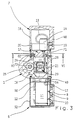
- the non-contact controlled sanitary fitting shown can be divided into five main components:
- a swivel spout 3 is attached to a central main housing 1, to which a base part 2 is attached at the bottom.
- Inlet channels 4 for hot and cold water penetrate the base part 2.
- Flexible water supply hoses 5 are screwed into these from below.
- two handle-like extensions 6 and 7 are attached to the main housing 1.
- the left handle-like extension 6 has only the external appearance, but not the function of a handle. It is only used to hold the electronic components of the non-contact valve.
- the optical entry and exit window 8 for that used to detect a user Infrared light shown.
- the window 8 is colored dark, so that its function as an optical window and the transmitter diode 9 behind it and the receiver diode 10 cannot be seen (see the section in FIG. 3).
- FIG. 3 it can be seen how the electronics 11 are accommodated inside the handle-like extension 6, which is supplied with the supply voltage via a cable 12 on the one hand and which is connected to a solenoid valve 14 via a further cable 13 in a manner yet to be described which controls the flow of water.
- the cable 12 is made via an axially parallel bore 15 in the main housing 1 or the base part 2 and an oblique bore 16 in the main housing 1 from the sanitary fitting.
- the right handle-like approach 7 is not only "handle-like" in the illustrated embodiment, so it not only sees a conventional sanitary fitting handle but actually has this function. It can be rotated about its horizontal axis to adjust the temperature of the mixed water flowing out of the sanitary fitting. In the case of a sanitary fitting which only releases water at a single temperature, the attachment 7 would also only be "similar" to the handle, ie it would not really perform the function of a handle, but would only pretend the presence of such a handle.
- FIGS. 4 and 5 have a larger scale than FIGS. 1 to 3.
- the cup-shaped outer housing 18 of the handle-like extension 7 is omitted in FIGS. 4 and 5 for the sake of clarity. It is fastened with a screw 19 to a cylindrical skirt 20 of the grater 17, as can be seen in FIG. 3.
- the outer housing 18 is rotated, the entire grater 17 is taken along, which changes the mixing ratio of cold and hot water in a manner to be described.
- the grater 17 is a one-piece molded part which projects into a cylindrical chamber 21 of the main housing 1 at the end facing away from the apron 20. Bores 22, 23 (see also FIG. 5), which pass obliquely through the main housing 1 and which communicate with the bores 4 in the base part 2 and through which cold and hot water can thus reach the cylindrical chamber 21, open into this chamber 21. Axially offset from the bores 22 and 23, another bore 24 of the main housing 1 opens into the cylindrical chamber 21, which is connected to a vertical bore 25 leading to the outlet 3. This can be seen in particular in FIG. 3.
- the inner end of the grater 17 used, the water flowing through the hoses 5, the channels 4, 22 and 23 into the cylindrical chamber 21 of the main housing 1 could flow directly through the bores 24 and 25 to the outlet 3.
- the setting of the mixing ratio of cold and hot water is done by an essentially cylindrical head 26 of the grater 17, in which an oblique groove 27 is incorporated.
- the groove 27 cuts the channels 22 and 23 in the main housing differently depending on the rotational position.
- FIG. 5 shows the position in which the same proportions of cold and hot water are obtained because the channels 22 and 23 both open to the same extent, namely half, into the groove 27. Water can therefore flow into the groove 27 from the channels 22 and 23.
- the groove 27 guides the mixing water into a recess 28 on the outer circumference of the head 26 of the grater 17, from where it can reach the end of the grater 17.
- An elastic cushion 79 is embedded in the lower region of the lateral surface of the grater head 26. If the grater 17 is turned to the full cold position, the cushion 79 lies over the mouth of the bore 22 supplying the hot water and closes it tightly. This prevents hot water losses.
- the further path of the mixed water arriving at the open end face of the grater 17 to the channel 24 and thus to the outlet 3 leads via the interior of the hollow head 26 of the grater 17, in which a pilot-controlled valve 29 is accommodated, and via a radial bore 44 in the grater 17 and an annular space 78, which lies between the wall of the chamber 21 and a reduced-diameter area of the grater 17.
- the annular space 78 becomes axial Direction limited by two O-rings 56 and 57, which are arranged in grooves on the outer surface of the grater 17.
- the pilot-controlled valve 29 comprises, as closing elements, a membrane 30 made of elastic material and a cage 31 made of rigid plastic, with which the membrane 30 cooperates. Although this is shown in one piece in the drawing, it can also be constructed in several parts.
- the elastic membrane 30 has the shape of two truncated cones, which are arranged in opposite directions, with beads 32, 33 projecting radially inwards on the axially opposite ends.
- the cage 31 comprises a central contact body 34 and at both axial ends a support ring 35 and 36, respectively, which cooperates with the bead 32, 33 of the elastic membrane 30 located there.
- the contact body 34 of the cage 31 is connected to the support rings 35, 36 via ribs 37 to form a unit.
- Cage 31 and membrane 30 tied thereon lie against a step in the interior of the grater and are releasably secured at the outer end by an insert ring 46 and a snap ring 47.
- the elastic membrane 30 is shaped such that it normally rests against the outside of the contact body 34 of the cage 31, ie without pressure from water from inside or outside. This is the closed state of the pilot-controlled valve 29, since then the water path through the interior of the grater 17 to the channel 24 is blocked by the contact body 34 and the membrane 29.
- the membrane 29 can move from the closed position shown into an open position by lifting off from the contact body 34 in the central region and resting against the wall of the cylindrical chamber 21 of the main housing 1. An annular space between the membrane 29 and the contact body 24 is released for flow.
- the inner space of the membrane 29 below the contact body 34 is connected to the outer space by a small radial compensating bore 38.
- This in turn communicates via an axially parallel channel 39 with a recess 40 on the outer end face of the grater 17, which is located radially inside the apron 20.
- the recess 40 is covered by the underside of the magnet coil 14 and sealed by an O-ring 45.
- a valve seat 41 is formed, which cooperates with a closing body 42.
- the closing body 42 normally closes the valve seat 41 and thus the access to an axially parallel channel 43, which leads to the radial bore 44 in the grater 17 and thus to the channel 24 in the main housing 1.
- the units held or formed by the handle-like extensions 6 and 7 are preassembled.
- the housing 52 has a thread at its open end, into which a ring 49 is screwed.
- Two screws 50, 51 extend transversely through the main housing 1 and are screwed with their threaded ends into threaded holes in the ring 49.
- the heads of the screws 50, 51 lie against countersinking in the right side surface of the main housing 1 in FIG. 1.
- the left handle-like extension 6 is thus attached to the main housing 1.
- the cable 12 is of course still run through the channels 15 and 16; the cable 13 is led through a channel 53 which completely penetrates the main housing 1 (cf. also FIG. 2) to the other side surface of the main housing 1.
- a cylindrical collar 54 at the inner end of the housing 52 protrudes into a groove on the left side surface of the main housing 1 in FIG. 1. This results in a visually pleasing transition between the handle-like extension 6 and the main housing 1.
- the grater 17 is provided with a groove 58 at that axial point at which the right-hand side face of the main housing 1 comes to rest in the installed state.
- a U-shaped fastening part 59 is inserted into this groove 58 from the side.
- This is screwed with three screws 60, 61 and 62 to the right side surface of the main housing 1 in FIG. 1.
- One of these screws, namely screw 60, is shown in FIGS. 4 and 5; all three screws can be seen in Figure 6, which represents a section along line VI-VI of Figure 3, at the level of the heads of the screws 60, 61, 62.
- the heads of the screws 60, 61, 62 are accessible through recesses 63, 64, which extend axially parallel through the outer part of the 17 up to the right end in FIG. 1. These recesses 63, 64 can alternately be aligned by rotating the grater 17 be brought with the heads of the screws 60, 61, 62 so that the screws 60, 61, 62 can be inserted here and tightened with a screwdriver.
- the angle through which the grater 17 can be rotated to adjust the temperature of the outflowing mixed water can be set in the following way:
- a further recess 65 is provided in the outer contour of the grater 17, but this has a larger diameter than the groove 58 and is not completely guided around the circumference of the grater 17 is. Rather, as can be seen in FIG. 6, a dovetail-shaped extension 66 projects radially outward from the "core" 67 of the grater 17. This dovetail-shaped extension 66 limits the rotatability of the grater 17 in FIG. 6 clockwise by coming into contact with the head of the screw 60.
- An arcuate elongated hole 68 penetrates the wall between the annular shoulder, which is formed by the recess 65 against the portion of the grater 17 which carries the apron 20, and the outer end wall of the grater 17, which is surrounded by the apron 20 and onto which the magnet coil 14 is also placed is.
- a screw 69 is guided through this slot 68 from the outside and holds a stop piece 70 on the aforementioned annular shoulder of the recess 65.
- the stop piece 70 runs radially from the "core" 67 of the grater 17 to the outer circumference of the annular shoulder formed by the recess 65. It limits the rotatability of the grater 17 counterclockwise by coming to bear against the head of the screw 60. The entire angle of rotation that the grater 17 can measure is evident from the variable position of the stop piece 70 in the arcuate elongated hole 68 determined.
- the head of the screw 19 in the handle 18 is covered with a window 48, the appearance of which corresponds to the window 8 in the handle-like attachment 6 on the left in FIG. Externally, as can be seen in FIG. 1, there is a completely symmetrical appearance.
- the main housing 1 is fastened to the base part 2 by a central screw 72 (FIG. 2), the head of which lies in the upper region in the bore 25 already mentioned, which leads the mixed water flowing from the cylindrical chamber 21 to the outlet 3.
- the downward waterway is blocked in FIG. 2 by a sealing ring 73, which is arranged between the head of the screw 72 and the ring shoulder of the bore 25 below it.
- a mounting piece 74 is screwed into the latter from above.
- the attachment piece 74 has a somewhat larger diameter in the upper region and is located here via O-rings on the inner wall of outlet 3. This is pushed over the mounting piece 74 to close to the upper end face of the main housing 1.
- a U-shaped fastening part 75 lies between the inner wall of the outlet 3 and the region of the fastening socket 74 which is reduced in diameter.
- the outlet 3 is fixed to it by means of a screw 76.
- the fastening part 75 bears with a projection 77 which extends in the axial direction against an annular step which connects the region of the fastening socket 74 which has a larger diameter with the region of smaller diameter.
- the outlet 3 is fixed in the axial direction.
- the axial projection 77 simultaneously acts as a limitation for the angle of rotation which the outlet 3 can measure with respect to the main housing 1.
Landscapes
- Health & Medical Sciences (AREA)
- Life Sciences & Earth Sciences (AREA)
- Engineering & Computer Science (AREA)
- Hydrology & Water Resources (AREA)
- Public Health (AREA)
- Water Supply & Treatment (AREA)
- Multiple-Way Valves (AREA)
- Domestic Plumbing Installations (AREA)
- Toys (AREA)
- Mechanically-Actuated Valves (AREA)
Applications Claiming Priority (2)
| Application Number | Priority Date | Filing Date | Title |
|---|---|---|---|
| DE4102134 | 1991-01-25 | ||
| DE4102134A DE4102134C2 (de) | 1991-01-25 | 1991-01-25 | Berührungslos gesteuerte Sanitärarmatur |
Publications (2)
| Publication Number | Publication Date |
|---|---|
| EP0496105A1 true EP0496105A1 (fr) | 1992-07-29 |
| EP0496105B1 EP0496105B1 (fr) | 1994-10-05 |
Family
ID=6423661
Family Applications (1)
| Application Number | Title | Priority Date | Filing Date |
|---|---|---|---|
| EP91122089A Expired - Lifetime EP0496105B1 (fr) | 1991-01-25 | 1991-12-22 | Armature sanitaire pour un fonctionnement à distance |
Country Status (6)
| Country | Link |
|---|---|
| US (1) | US5167255A (fr) |
| EP (1) | EP0496105B1 (fr) |
| JP (1) | JP3378265B2 (fr) |
| AT (1) | ATE112617T1 (fr) |
| DE (1) | DE4102134C2 (fr) |
| ES (1) | ES2064030T3 (fr) |
Cited By (2)
| Publication number | Priority date | Publication date | Assignee | Title |
|---|---|---|---|---|
| EP0631078A1 (fr) * | 1993-03-18 | 1994-12-28 | SOL S.p.A. | Mitigeur avec un robinet à membrane |
| CN111237177A (zh) * | 2019-11-21 | 2020-06-05 | 山东青耕电气有限公司 | 一种改进型机械式液体连续换向装置 |
Families Citing this family (9)
| Publication number | Priority date | Publication date | Assignee | Title |
|---|---|---|---|---|
| DE4106540C2 (de) * | 1991-03-01 | 1994-09-29 | Hansa Metallwerke Ag | Sanitärarmatur |
| DE19810699A1 (de) * | 1998-03-12 | 1999-09-16 | Grohe Armaturen Friedrich | Wasserarmatur |
| DE19956401A1 (de) * | 1999-11-24 | 2001-05-31 | Grohe Armaturen Friedrich | Wasserarmatur |
| US20070194137A1 (en) * | 2006-02-17 | 2007-08-23 | Watts Water Technologies, Inc. | Thermostatic mixing valve |
| US7389793B2 (en) * | 2006-06-27 | 2008-06-24 | Hsiang Hung Wang | Faucet device selectively operatable manually or automatically |
| US8474481B2 (en) * | 2011-03-29 | 2013-07-02 | Hydrotek Corporation | Manual/automatic and cold/hot faucet with a ceramic valve |
| US10036150B2 (en) * | 2016-05-31 | 2018-07-31 | Xiamen Forbetter Sanitary Ware Co., Ltd. | Automatic faucet |
| US10612221B2 (en) * | 2018-04-25 | 2020-04-07 | Xiamen Forbetter Sanitary Ware Co., Ltd. | Intelligent faucet structure based on photoelectric detection device |
| CN112066044A (zh) * | 2020-09-02 | 2020-12-11 | 厦门方特卫浴有限公司 | 一种多控制龙头 |
Citations (5)
| Publication number | Priority date | Publication date | Assignee | Title |
|---|---|---|---|---|
| DE3537678A1 (de) * | 1985-10-23 | 1987-04-23 | Peter Wilfred Auge | Beruehrungslos betaetigbare absperrarmatur fuer fluessigkeiten |
| DE3731679A1 (de) * | 1987-09-21 | 1989-04-06 | Hansa Metallwerke Ag | Beruehrungslos gesteuerte sanitaerarmatur |
| JPH01203530A (ja) * | 1988-02-06 | 1989-08-16 | Toto Ltd | 自動水栓 |
| DE3905759C1 (fr) * | 1989-02-24 | 1990-03-29 | Cosmos Entwicklungs- Und Forschungsanstalt, Vaduz, Li | |
| DE4004099A1 (de) * | 1989-02-24 | 1990-08-30 | Cosmos Entwicklung Forsch | Sanitaerarmatur fuer wasserhaehne |
Family Cites Families (9)
| Publication number | Priority date | Publication date | Assignee | Title |
|---|---|---|---|---|
| US1664612A (en) * | 1925-11-04 | 1928-04-03 | Louis O French | Fuel-control valve |
| US3193248A (en) * | 1961-11-20 | 1965-07-06 | Acf Ind Inc | Ball valve seat construction |
| US3559684A (en) * | 1968-10-24 | 1971-02-02 | Speakman Co | Rotatable and reciprocal mixing valve and adjustment limit stop |
| US4051869A (en) * | 1976-01-12 | 1977-10-04 | Crane Co. | Mixing valve |
| US4681141A (en) * | 1986-02-03 | 1987-07-21 | Wang Wen Ching | Light-detector, hand-controlled faucet with water temperature regulator |
| US4741363A (en) * | 1986-10-29 | 1988-05-03 | Hydrotek Corporation | Fluid faucet |
| US4826129A (en) * | 1988-05-03 | 1989-05-02 | Caprilion Enterprise Company | Structure of faucet for automatic water supply and stoppage |
| IT1226220B (it) * | 1988-08-22 | 1990-12-21 | Galatron Srl | Perfezionamenti alle valvole miscelatrici di acqua calda e fredda |
| US5050641A (en) * | 1990-05-08 | 1991-09-24 | Shwu Fen Sheu | Photoelectric single handle faucet |
-
1991
- 1991-01-25 DE DE4102134A patent/DE4102134C2/de not_active Expired - Fee Related
- 1991-12-22 EP EP91122089A patent/EP0496105B1/fr not_active Expired - Lifetime
- 1991-12-22 AT AT91122089T patent/ATE112617T1/de not_active IP Right Cessation
- 1991-12-22 ES ES91122089T patent/ES2064030T3/es not_active Expired - Lifetime
-
1992
- 1992-01-22 US US07/824,096 patent/US5167255A/en not_active Expired - Fee Related
- 1992-01-27 JP JP01219492A patent/JP3378265B2/ja not_active Expired - Fee Related
Patent Citations (5)
| Publication number | Priority date | Publication date | Assignee | Title |
|---|---|---|---|---|
| DE3537678A1 (de) * | 1985-10-23 | 1987-04-23 | Peter Wilfred Auge | Beruehrungslos betaetigbare absperrarmatur fuer fluessigkeiten |
| DE3731679A1 (de) * | 1987-09-21 | 1989-04-06 | Hansa Metallwerke Ag | Beruehrungslos gesteuerte sanitaerarmatur |
| JPH01203530A (ja) * | 1988-02-06 | 1989-08-16 | Toto Ltd | 自動水栓 |
| DE3905759C1 (fr) * | 1989-02-24 | 1990-03-29 | Cosmos Entwicklungs- Und Forschungsanstalt, Vaduz, Li | |
| DE4004099A1 (de) * | 1989-02-24 | 1990-08-30 | Cosmos Entwicklung Forsch | Sanitaerarmatur fuer wasserhaehne |
Cited By (2)
| Publication number | Priority date | Publication date | Assignee | Title |
|---|---|---|---|---|
| EP0631078A1 (fr) * | 1993-03-18 | 1994-12-28 | SOL S.p.A. | Mitigeur avec un robinet à membrane |
| CN111237177A (zh) * | 2019-11-21 | 2020-06-05 | 山东青耕电气有限公司 | 一种改进型机械式液体连续换向装置 |
Also Published As
| Publication number | Publication date |
|---|---|
| EP0496105B1 (fr) | 1994-10-05 |
| ES2064030T3 (es) | 1995-01-16 |
| US5167255A (en) | 1992-12-01 |
| DE4102134A1 (de) | 1992-07-30 |
| DE4102134C2 (de) | 1995-09-07 |
| ATE112617T1 (de) | 1994-10-15 |
| JPH04306330A (ja) | 1992-10-29 |
| JP3378265B2 (ja) | 2003-02-17 |
Similar Documents
| Publication | Publication Date | Title |
|---|---|---|
| EP0312781A1 (fr) | Armature sanitaire à commande sans contact | |
| EP2976558B1 (fr) | Vanne à double siège avec entraînement de commande | |
| DE4328064A1 (de) | Sensor- und batteriebetriebenes Spülventil mit Membrananschlag | |
| DE2320499C3 (de) | Druckregler für ein Kältemittel | |
| DE19623104C2 (de) | Als Einhebelmischer ausgebildete Sanitärarmatur | |
| DE3800305C1 (fr) | ||
| EP0496105B1 (fr) | Armature sanitaire pour un fonctionnement à distance | |
| DE102005026105A1 (de) | Ventil mit Endlagenschaltung | |
| EP0496104B1 (fr) | Soupape mélangeur sanitaire | |
| DE68923248T2 (de) | Ventil für Druckmittel. | |
| DE4025488C2 (de) | Rückschlagventil | |
| EP0930402B1 (fr) | Valve magnétique, en particulier pour des installations sanitaires | |
| DE10248616A1 (de) | Proportionalventil | |
| EP0955472B1 (fr) | Soupape à siège | |
| EP0845602B1 (fr) | Dispositif de commande electrohydraulique | |
| DE2944520A1 (de) | Ventiloberteil | |
| DE2544347A1 (de) | Ventilanordnung mit zwei stufen | |
| DE3911701C2 (fr) | ||
| EP0220358A1 (fr) | Soupape sanitaire | |
| DE2442482B2 (de) | Ventilanordnung zum Steuern des Wasserzulaufs zu einer oder mehreren Wasserabgabestellen | |
| CH641260A5 (en) | Pressure control (relief) valve for hydraulic control systems | |
| DE2712491A1 (de) | Vorrichtung zur signalwandlung | |
| DE4415134A1 (de) | Nockenanordnung zur Benutzung in Drehstellungs-Anzeigegeräten | |
| DE3731679C2 (fr) | ||
| DE3929889A1 (de) | Sicherheitseinrichtung fuer einen wasserzulauf |
Legal Events
| Date | Code | Title | Description |
|---|---|---|---|
| PUAI | Public reference made under article 153(3) epc to a published international application that has entered the european phase |
Free format text: ORIGINAL CODE: 0009012 |
|
| AK | Designated contracting states |
Kind code of ref document: A1 Designated state(s): AT CH ES FR GB IT LI |
|
| 17P | Request for examination filed |
Effective date: 19920613 |
|
| 17Q | First examination report despatched |
Effective date: 19930916 |
|
| GRAA | (expected) grant |
Free format text: ORIGINAL CODE: 0009210 |
|
| AK | Designated contracting states |
Kind code of ref document: B1 Designated state(s): AT CH ES FR GB IT LI |
|
| REF | Corresponds to: |
Ref document number: 112617 Country of ref document: AT Date of ref document: 19941015 Kind code of ref document: T |
|
| ET | Fr: translation filed | ||
| ITF | It: translation for a ep patent filed | ||
| REG | Reference to a national code |
Ref country code: ES Ref legal event code: FG2A Ref document number: 2064030 Country of ref document: ES Kind code of ref document: T3 |
|
| GBT | Gb: translation of ep patent filed (gb section 77(6)(a)/1977) |
Effective date: 19941221 |
|
| PLBE | No opposition filed within time limit |
Free format text: ORIGINAL CODE: 0009261 |
|
| STAA | Information on the status of an ep patent application or granted ep patent |
Free format text: STATUS: NO OPPOSITION FILED WITHIN TIME LIMIT |
|
| 26N | No opposition filed | ||
| PGFP | Annual fee paid to national office [announced via postgrant information from national office to epo] |
Ref country code: ES Payment date: 19991203 Year of fee payment: 9 |
|
| PGFP | Annual fee paid to national office [announced via postgrant information from national office to epo] |
Ref country code: FR Payment date: 19991210 Year of fee payment: 9 Ref country code: AT Payment date: 19991210 Year of fee payment: 9 |
|
| PGFP | Annual fee paid to national office [announced via postgrant information from national office to epo] |
Ref country code: CH Payment date: 19991214 Year of fee payment: 9 |
|
| PGFP | Annual fee paid to national office [announced via postgrant information from national office to epo] |
Ref country code: GB Payment date: 19991222 Year of fee payment: 9 |
|
| PG25 | Lapsed in a contracting state [announced via postgrant information from national office to epo] |
Ref country code: GB Free format text: LAPSE BECAUSE OF NON-PAYMENT OF DUE FEES Effective date: 20001222 Ref country code: AT Free format text: LAPSE BECAUSE OF NON-PAYMENT OF DUE FEES Effective date: 20001222 |
|
| PG25 | Lapsed in a contracting state [announced via postgrant information from national office to epo] |
Ref country code: LI Free format text: LAPSE BECAUSE OF NON-PAYMENT OF DUE FEES Effective date: 20001231 Ref country code: CH Free format text: LAPSE BECAUSE OF NON-PAYMENT OF DUE FEES Effective date: 20001231 |
|
| GBPC | Gb: european patent ceased through non-payment of renewal fee |
Effective date: 20001222 |
|
| REG | Reference to a national code |
Ref country code: CH Ref legal event code: PL |
|
| PG25 | Lapsed in a contracting state [announced via postgrant information from national office to epo] |
Ref country code: FR Free format text: LAPSE BECAUSE OF NON-PAYMENT OF DUE FEES Effective date: 20010831 |
|
| REG | Reference to a national code |
Ref country code: FR Ref legal event code: ST |
|
| PG25 | Lapsed in a contracting state [announced via postgrant information from national office to epo] |
Ref country code: ES Free format text: LAPSE BECAUSE OF NON-PAYMENT OF DUE FEES Effective date: 20011223 |
|
| REG | Reference to a national code |
Ref country code: ES Ref legal event code: FD2A Effective date: 20020112 |
|
| PG25 | Lapsed in a contracting state [announced via postgrant information from national office to epo] |
Ref country code: IT Free format text: LAPSE BECAUSE OF NON-PAYMENT OF DUE FEES;WARNING: LAPSES OF ITALIAN PATENTS WITH EFFECTIVE DATE BEFORE 2007 MAY HAVE OCCURRED AT ANY TIME BEFORE 2007. THE CORRECT EFFECTIVE DATE MAY BE DIFFERENT FROM THE ONE RECORDED. Effective date: 20051222 |