EP0496156A2 - Appareil ultrasonore de mesure d'écoulement d'air - Google Patents
Appareil ultrasonore de mesure d'écoulement d'air Download PDFInfo
- Publication number
- EP0496156A2 EP0496156A2 EP91310874A EP91310874A EP0496156A2 EP 0496156 A2 EP0496156 A2 EP 0496156A2 EP 91310874 A EP91310874 A EP 91310874A EP 91310874 A EP91310874 A EP 91310874A EP 0496156 A2 EP0496156 A2 EP 0496156A2
- Authority
- EP
- European Patent Office
- Prior art keywords
- air flow
- detector
- speed
- transmitter
- burst
- Prior art date
- Legal status (The legal status is an assumption and is not a legal conclusion. Google has not performed a legal analysis and makes no representation as to the accuracy of the status listed.)
- Granted
Links
Images



Classifications
-
- G—PHYSICS
- G01—MEASURING; TESTING
- G01S—RADIO DIRECTION-FINDING; RADIO NAVIGATION; DETERMINING DISTANCE OR VELOCITY BY USE OF RADIO WAVES; LOCATING OR PRESENCE-DETECTING BY USE OF THE REFLECTION OR RERADIATION OF RADIO WAVES; ANALOGOUS ARRANGEMENTS USING OTHER WAVES
- G01S11/00—Systems for determining distance or velocity not using reflection or reradiation
- G01S11/14—Systems for determining distance or velocity not using reflection or reradiation using ultrasonic, sonic or infrasonic waves
-
- G—PHYSICS
- G01—MEASURING; TESTING
- G01P—MEASURING LINEAR OR ANGULAR SPEED, ACCELERATION, DECELERATION, OR SHOCK; INDICATING PRESENCE, ABSENCE, OR DIRECTION, OF MOVEMENT
- G01P5/00—Measuring speed of fluids, e.g. of air stream; Measuring speed of bodies relative to fluids, e.g. of ship, of aircraft
- G01P5/24—Measuring speed of fluids, e.g. of air stream; Measuring speed of bodies relative to fluids, e.g. of ship, of aircraft by measuring the direct influence of the streaming fluid on the properties of a detecting acoustical wave
- G01P5/245—Measuring speed of fluids, e.g. of air stream; Measuring speed of bodies relative to fluids, e.g. of ship, of aircraft by measuring the direct influence of the streaming fluid on the properties of a detecting acoustical wave by measuring transit time of acoustical waves
Definitions
- This invention relates to an apparatus for measuring the speed of an air flow.
- the first type of instrument has a "fan” which rotates in the wind and is either optically coupled or "Hall Effect” coupled to a counter which counts the rotations and displays the result as an air flow speed.
- these devices have appreciable inertia and resistance to movement and are of sufficient size that they cause a significant deflection of the air flow they are trying to measure. Thus they are very inaccurate, especially at low air flow speeds.
- the second type of instrument uses a heating element which is heated up to a know fixed temperature, and when the element is exposed to a flow of air the instrument calculates the power required to maintain the known fixed temperature.
- the power required is related to the air flow speed.
- This type of instrument is very sensitive to movements of air, but it is not very accurate and has a high power consumption.
- an apparatus for measuring the speed of an air flow comprising a sonic transmitter and a sonic deatector mounted spaced apart for insertion in the air flow, means for causing the transmitter to transmit at least one burst of sound towards the detector, and means for deriving the speed of the air flow as a function of the time taken for the burst to reach the detector.
- the transmitter and detector comprise respective ultrasonic transducers mounted on the exterior of a portable hand-held housing.
- the apparatus has a feedback circuit between the transmitter and the detector operative to trigger the transmitter to transmit a further burst of sound in response to the detection of a previous burst of sound at the detector, such that a single initial burst transmitted by the transmitter produces a series of following bursts, and wherein the means for deriving the speed of the air flow comprises means for counting the number of bursts detected in a pre-determined time period.
- the period of time for which the bursts are counted is one second.
- the burst transmitted by the transmitter is preferably of ultrasonic frequency, that is to say greater than 35KHz, to avoid interference from ambient noise at acoustic frequencies.
- the frequency of the burst is 100KHz.
- the transmitter and detector preferably have a very low Q, of about one, to permit the transmission and detection of many very short well-defined bursts, say 5000 or more bursts per second each 40us (40 microseconds) in duration. This permits the transmitter and detector to be located quite close together, say 0.1 metre or less apart, because then the transmitter will have finished transmitting one burst before it is triggered to transmit the next, so that the bursts are clearly distinguishable at the detector.
- the transmitter and detector may have a higher Q, but this leads to ringing and a less well defined start and finish to each burst, so that the transmitter and detector have to be further apart to ensure that each individual burst is reliably detected at the detector. This is within the scope of the invention, but a small transmitter/detector gap is preferred because it permits the apparatus to be built as a very compact portable hand-held device.
- each transducer comprises a film of piezoelectric material having two at least partially overlapping electrodes respectively in intimate contact with each of its two opposite surfaces, the film being mounted on a support member.
- These can be constructed to have a low Q, as preferred for this invention.
- Such piezoelectric film transducers have utility in applications other than for measuring the speed of an air flow, and thus constitute an independent invention.
- the apparatus comprises a portable hand-held housing 10 from the top of which project two support members 11 and 12 carrying ultrasonic transducers 13 and 14 respectively.
- the transducer 13 is an ultrasonic transmitter
- the transducer 14 is an ultrasonic detector. They are fixed 0.1 metre (about 4 inches) apart.
- the transducers preferably having a very low Q, as near to one as possible, and their construction will be described below.
- the front face of the housing 10 has an ON-OFF switch 15, and a keypad comprising a number of push-button keys 16-21.
- a keypad comprising a number of push-button keys 16-21.
- AUTO key 16 a CALIBRATE key 17
- start or GO key 18 a keypad comprising a number of push-button keys 16-21.
- LCD liquid crystal display
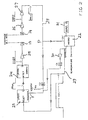
- the internal circuit of the apparatus comprises a LM555 timer chip 23 configured as a monostable. Provided that its RESET input is high, the monostable 23 is triggered by each negative-going edge at its TRIGGER input to provide a respective single output pulse at its Q output of 40us (40 microseconds) duration.
- a further LM555 timer chip 24, in this case configured as a 100 KHz gated oscillator, has its RESET input connected to the Q output of the monostable 23.
- Each 40us output pulse from the monostable 23 is thus applied to the RESET input of the oscillator 24, and serves to gate the oscillator.
- the oscillator 24 provides a short burst of oscillations of 40us duration at its Q output in response to each such 40us pulse from the monostable 23. Since the oscillator frequency is 100KHz, each burst comprises about 4 cycles.
- Each 40us burst from the oscillator is applied to the ultrasonic transmitter 13 via a driver 25.
- the transmitter transmits a 40us burst of ultrasound across the 0.1 metre gap towards the ultrasonic detector 14.
- the burst When received at the detector 14, the burst is amplified in the high gain amplifier 26 back to the circuit VCC of 5 volts, and then passes to an envelope detector (pump circuit) 27 which reconstitutes (so far as circuit degredation will allow) the original 40us burst from the monostable 23, and inverts it.
- an envelope detector (pump circuit) 27 which reconstitutes (so far as circuit degredation will allow) the original 40us burst from the monostable 23, and inverts it.
- This inverted pulse CK passes along a feedback line 28 to an RC circuit consisting of a capacitor C2 and a resistor R1.
- This RC circuit derives a short negative-going pulse of about 1us (1 microsecond) from the leading (negative-going) edge of the inverted pulse from the envelope detector 27, which is applied to the TRIGGER input of the monostable 23.
- the rate at which the ultrasonic bursts follow one another. and hence the rate at which the inverted pulses appear on the line 28, is directly proportional to the speed of air flowing in the direction from the transmitter 13 to the detector 14, provided the transducers are stationary.
- the apparent speed of sound between the transducers is (V + S) where V is the speed of the air flow and S is the speed of sound in still air.
- the basic principle of operation of the apparatus is to measure this rate when the transducers 13 and 14 are located in the air flow, with the transducer 14 directly downstream of the transducer 13, in particular by counting the number of pulses CK passing the point P on the line 28 in a fixed pre-determined period of time, in this case one second.
- the apparatus derives this reference number either by sampling the external air temperature using a thermistor probe and determining the reference number using the known relationship between the speed of sound in still air and temperature, or by actually measuring the reference number by performing a calibration measurement in still air.
- a programmed microprocessor 22 which has inputs from the point P on the line 28 and from an external air temperature sensor (not shown) such as a thermistor probe, and provides out-puts to drive the display 31 and also an output to an ENABLE line 29.
- the ENABLE line 29 is connected directly to the RESET input of the monostable 23, so that while the ENABLE line 29 is held low the monostable cannot generate the 40us pulses mentioned above.
- the microprocessor can define each one-second counting period referred to above by raising the ENABLE line 29 for one second.
- the ENABLE line is connected via an inverter 30 and an RC circuit comprising a capacitor C1 and the resistor R1 to the TRIGGER input of the monostable 23.
- each leading (positive-going) edge on the ENABLE line 29 will first be inverted and then via the RC circuit provide a short 1us negative-going pulse to the TRIGGER input of the monostable 23.
- the microprocessor Upon power on (ON-OFF switch 15, Figure 1) the microprocessor initialises, including setting the ENABLE line 29 low, step 40.
- step 41 the microprocessor calculates a reference number which is the number of inverted pulses which would be detected at the point P on line 28 during a one-second period if the apparatus were operated as described above the transducers 13 and 14 in still air at the temperature of the thermistor probe.
- This number is uniquely defined by the separation (0.1) meter of the transducers 13 and 14 and the speed of sound in still air at the temperature concerned, since there is a known relationship between the speed of sound in still air and temperature.
- the reference number may be obtained from a look-up table stored internally in the microprocessor, different values of the reference number corresponding to different temperatures having been pre-calculated. In fact, in the present case where the gap between the transducers is 0.1 metre, the reference number will be ten times the speed of sound in still air, in metres per second, at the temperature concerned.
- the reference number is stored in an internal register (register A) in step 43.
- step 44 the AUTO button 16 ( Figure 1) is polled to see if it is currently pressed. If it is not the CALIBRATE button 18 is likewise polled in step 45, and if that is also not pressed the GO button 17 is polled in step 46. If the GO button is not pressed then the program loops back to the temperature sensing step 41. Thus all the while that none of the AUTO, CALIBRATE and GO buttons are pressed, the program cycles round steps 41 to 46, updating the stored reference number each time in accordance with changes at ambient temperature.
- step 47 the program will branch to step 47, and set a flag (flag 2) to "AUTO". Now the program waits 200ms (200 milliseconds) in step 48 to allow any transients which may have been generated by pressing the button to die away. .
- step 49 the program sets the ENABLE line 29 high, and at the same time starts an internal timer to measure a one-second period.
- putting the ENABLE line 29 high enables the monostable 23 to generate 40us pulses, and further the leading edge of the ENABLE line 29 going high will cause the monostable 23 to generate an initial such 40us pulse via the inverter 30 and the RC circuit.
- step 50 the microprocessor waits for a pulse on the line 28 and when one is detected it increments a counter (register R) in step 51. Then in step 52 it looks to see if the internal timer has measured one second. If not the program loops back to step 50. The program cycles round this loop until the internal timer shows that one second has elapsed.
- step 53 the program goes to step 53, where it puts the ENABLE line 29 low. This stops the further generation and circulation of bursts and pulses by lowering the RESET input to the monostable 23.
- the count then in the register R is the total number of pulses which have passed the point P, and hence the number of bursts of ultrasound which have passed across the 0.1 metre gap between the transducers 13 and 14, in the preceding one second interval.
- the number in the register R will be ten times the speed of sound (in metres per second) relative to the transducers, which must be held stationary in the moving air with the transducer 14 downstream of the transducer 13 for a correct measurement to be taken.
- step 54 the program tests whether the flag 2 is set to "AUTO". Since it was so set in step 47, the grogram moves to step 55, where it subtracts the reference number stored in the register A (step 43) from the current number stored in the register R. The result is ten times the speed of air flow across the transducer gap, in metres per second. This result is converted to the appropriate format, e.g. knots, miles per hour, etc., and displayed on the LCD 31 in step 57. A simple division by ten will give the air flow speed in metres per second.
- step 70 the program loops back to step 41 via step 70, where flag 2 is reset, and provided the AUTO button is held down the whole process cycles through again, thereby repeatedly updating the reference number stored in the register A and measuring the current air flow speed.
- step 64 one has in the register M a reference number which is the number of inverted pulses CK which were detected at the point P on line 28 during the immediately preceding one-second period.
- This is referred to as the reference number because the calibration, to be accurate, has to be performed in still air at the same temperature as the moving air whose speed it is desired to measure. It is assumed that this was the case.
- the reference number in the register M will be ten times the speed of sound in still air at the temperature concerned.
- step 46 the program moves to step 46, where it sees if the GO button is pressed. Assuming that it is, step 65 test the flag 1 for being set to "CALIBRATE", and since it has been the program repeats all of steps 48 to 53 previously described. Of course, it is assumed that the GO button will now have been pressed until the transducers were inserted in the air flow to be measured.
- step 53 the count then in the register R is, as previously described, the total number of pulses CK which have passed the point P, and hence the number of bursts of ultrasound which have gassed across the 0.1 metre gap between the transducers 13 and 14, in the preceding one second interval. This will be ten times the speed of sound in metres per second of the ultrasonic bursts relative to the stationary transducers.
- step 54 the program again tests the flag 2 for being set at "AUTO". This time it isn't, because the flag was reset at step 70, or was never set if the AUTO button hasn't been pressed since power on, and thus the program moves to step 56 where it subtracts the reference number stored in the register M (step 62) from the current number stored in the register R. The result is ten times the speed of air flow across the transducer gap, in metres per second. Again this result is converted to the appropriate format and displayed on the LCD 31 in step 57.
- step 46 if the program detects that the GO button has been pressed and then finds in step 65 that the flag 1 has not been set to "CALIBRATE", indicating that no calibration has been performed, the program is forced back to step 41. This ensures that in the MANUAL mode the CALIBRATE button must be pressed before the GO button for the latter to have any effect.
- step 57 the program loops back to step 41 again, ready for another AUTO mode measurement, or another MANUAL mode measurement.
- the program can switch between AUTO and MANUAL modes at will.
- the reference number stored in the register A (step 43) is always kept current, whether the control program is simply cycling around steps 41 to 46, or performing a MANUAL mode calibration or moving air measurement.
- an AUTO mode measurement can be made at any time, even following a calibration.
- the corresponding reference number stored in register M is retained, and always available for use until updated by a new calibration measurement, even if the AUTO button and not the GO button is pressed immediately following a calibration.
- each transducer 13 and 14 is provided on a respective support column 11 or 12 of circular cross-section rigid plastics material, and comprises a strip 70 of piezoelectric film fastened to the column by, for example, double side adhesive tape 71.
- the piezoelectric film 70 is metallised on each side and may be that sold under the name "KYNAR Piezo Film” by Pennwalt Pietzo Film Ltd,, of Hillend Industrial Park, Dunfermline, Fife, Scotland.
- the double-sided adhesive tape 71 may be that sold under the name "Sellotape".
- the column 11 or 12 is about 3mm in diameter, and the piezoelectric strip is about 3mm wide in the vertical direction of the column.
- the film 70 extends at least around 180 degrees of the circumference of the column, as shown in Figures 4A and 4B.
- the strip 70 is shown set into a shallow circumferential recess 75 around the column, but this is not necessary.
- a circular recess 72 may be provided in the column 11 or 12 behind the piezoelectric film 70, centrally of the strip.
- the recess 72 may be about 0.02 deep and about 2mm in diameter.
- the recess may be filled with air, or a resilient damping material.
- the piezoelectric film 70 has two leads 73, formed of the same material as the film itself, extending from the opposite narrow edges of the film down the column for connection to the internal circuit of the apparatus, one lead being connected to the metallisation on one side of the film and the other lead being connected to the metallisation on the other side of the film.
- the transducers are mounted on the housing 10 ( Figure 1) with the recesses 72 facing one another.
- each transducer 13 and 14 is provided on a respective support column 11 or 12 is of rigid plastics material.
- the column 11 or 12 is of aerofoil-like cross-section, having a convex front portion 80, which in this case is substantially semi-circular, and a tapering rear portion 81.
- the transducer proper comprises a piezoelectric film 82 having in intimate contact with each of its two opposite surfaces a respective metal electrode 83 and 84.
- the electrodes 83 and 84 are not co-extensive with the film 82, but each extends from a respective one of the two lateral edges 85 of the film 82 to the central region 86 of the film, where it overlaps the other foil electrode.
- the laminate 82/83/84 is mounted around the semi-circular front portion 80 of the column 11 or 12, and is held in tension across a narrow strip of resilient damping material 87 which is mounted in the centre of the front portion 80.
- the laminate is first fixed at one edge 85 to the side of the column by, for example, a strip 88 of double-sided adhesive tape, then squeezed around the column across the strip of damping material 87, and then fixed at the other edge 85 to the other side of the column by a further strip 88 of double-sided adhesive tape. In this way the laminate is tensioned across the damping material 87, with the central overlap region 86 of the laminate immediately in front of the strip 87.
- Each electrode 83 and 84 has a respective integral lead 89 extending from a respective one of the edges 85 down the column 11 or 12 for connection to the internal circuitry of the apparatus.
- the piezoelectric film 82 is continued down each lead 89 to provide a support backing for each electrode.
- the transducers are mounted on the housing 10 ( Figure 1) with the central overlap regions 86 facing one another, i.e. with their tapering rear portions 81 pointing away from one another.
- the laminate consisting of the piezoelectric film 82 and the electrodes 83 and 84 may be made from a metallised piezoelectric film such as that sold under the name KYNAR by Pennwalt Piezo Film Limited, of Hillend Industrial Park, Dunfermline, Fife, Scotland.
- KYNAR is a piezoelectric film typically 28 or 52 microns thick which is metallised on each side to a thickness of about 6 microns, typically with copper, gold or silver.
- the electrodes 83 and 84 are formed by selectively etching the metallisation away on each side of the KYNAR film to leave the two overlapping electrodes 83 and 89 shown, with the integral leads 89.
- the double-sided adhesive tape 88 may be that sold under the name SELLOTAPE.
- the damping material 87 may be thick single-sided adhesive tape, also sold under the name SELLOTAPE.
- the transducer When the transducer is used as an ultrasonic transmitter an AC voltage of ultrasonic frequency is applied across the electrodes 89. This causes mechanical oscillation of the piezoelectric film 82, primarily in the overlap region 86. When the transducer is used as an ultrasonic detector vibration of the piezoelectric film 82 by an external sound wave will induce a corresponding voltage across the electrodes 89.
- the maximum frequency response of the transducer is dependent upon the distance d across the convex front portion 80 of the column 11 or 12. In the present case the distance d is 3mm, giving a maximum frequency response of 250Khz.
- the Q of the transducer is dependent upon the tension in the laminate 82/83/84 and the degree of resilience of the damping material 87.
- the strip of damping material 87 may be used instead of using the strip of damping material 87, as in figure 4 one may provide a shallow recess in the column 11 or 12 behind the overlap region 86, and the recess may be filled with a damping material. In such case the laminate 82/83/84 is tensioned across the recess.
- transducers constructed generally as above can, by suitable choice of the parameters mentioned, be designed to have a very low Q, of the order of one, permitting the transducer gap to be as low as 0.1 metre or less.
- transducers constructed as above are found to possess the ability to produce a reading which is on average the air flow speed in the vicinity of the apparatus. This is because the transmitter produces a saucer-shaped wavefront which expands as it travels towards the detector. If the air is moving at different speed on each side of the transducers, the centre of the wavefront, which is the part detected by the detector, tends to move at the average of the speeds of the air on either side.
Landscapes
- Physics & Mathematics (AREA)
- Engineering & Computer Science (AREA)
- General Physics & Mathematics (AREA)
- Acoustics & Sound (AREA)
- Multimedia (AREA)
- Aviation & Aerospace Engineering (AREA)
- Radar, Positioning & Navigation (AREA)
- Remote Sensing (AREA)
- Measuring Volume Flow (AREA)
- Investigating Or Analyzing Materials By The Use Of Ultrasonic Waves (AREA)
- Sampling And Sample Adjustment (AREA)
- Measurement Of Velocity Or Position Using Acoustic Or Ultrasonic Waves (AREA)
Applications Claiming Priority (2)
| Application Number | Priority Date | Filing Date | Title |
|---|---|---|---|
| IE426590 | 1990-11-26 | ||
| IE426590A IE904265A1 (en) | 1990-11-26 | 1990-11-26 | Air flow measuring apparatus |
Publications (3)
| Publication Number | Publication Date |
|---|---|
| EP0496156A2 true EP0496156A2 (fr) | 1992-07-29 |
| EP0496156A3 EP0496156A3 (en) | 1992-10-28 |
| EP0496156B1 EP0496156B1 (fr) | 1996-08-21 |
Family
ID=11039424
Family Applications (1)
| Application Number | Title | Priority Date | Filing Date |
|---|---|---|---|
| EP91310874A Expired - Lifetime EP0496156B1 (fr) | 1990-11-26 | 1991-11-26 | Appareil ultrasonore de mesure d'écoulement d'air |
Country Status (6)
| Country | Link |
|---|---|
| US (2) | US5282388A (fr) |
| EP (1) | EP0496156B1 (fr) |
| AT (1) | ATE141691T1 (fr) |
| DE (1) | DE69121547D1 (fr) |
| IE (1) | IE904265A1 (fr) |
| ZA (1) | ZA919330B (fr) |
Cited By (2)
| Publication number | Priority date | Publication date | Assignee | Title |
|---|---|---|---|---|
| US5583301A (en) * | 1994-11-09 | 1996-12-10 | National Environmental Products Ltd., Inc. | Ultrasound air velocity detector for HVAC ducts and method therefor |
| RU2159443C2 (ru) * | 1995-05-12 | 2000-11-20 | Локхид Мартин Корпорейшн | Система аэронавигационных данных |
Families Citing this family (9)
| Publication number | Priority date | Publication date | Assignee | Title |
|---|---|---|---|---|
| USD352909S (en) | 1993-07-23 | 1994-11-29 | Newman Andrew P | Pocket anemometer |
| US5735166A (en) * | 1994-12-12 | 1998-04-07 | Cosense, Inc. | Ultrasonic micro-sensor for level leak alert and interface detector |
| US6244114B1 (en) * | 1998-09-30 | 2001-06-12 | Jan Casimir Kowal | Airflow measurement device |
| JP3935356B2 (ja) * | 2001-02-05 | 2007-06-20 | サーパス工業株式会社 | 超音波流量計 |
| US20040020883A1 (en) * | 2002-08-02 | 2004-02-05 | Brokaw Paul E. | Adhesive mounted storage rack, method, and kit |
| CN101281057B (zh) * | 2007-04-02 | 2011-06-22 | 鸿富锦精密工业(深圳)有限公司 | 气流检测装置 |
| WO2009124230A2 (fr) * | 2008-04-04 | 2009-10-08 | Schweitzer Engineering Laboratories, Inc. | Indicateur de circuit triphasé en défaut |
| DK178244B1 (en) | 2013-06-21 | 2015-09-28 | Agena As | A system or a method for measuring flow in a flow duct |
| WO2018199928A1 (fr) * | 2017-04-25 | 2018-11-01 | Hewlett-Packard Development Company, L.P. | Dispositif de commande de turbine à fluide |
Family Cites Families (18)
| Publication number | Priority date | Publication date | Assignee | Title |
|---|---|---|---|---|
| US3729993A (en) * | 1971-03-08 | 1973-05-01 | Datamarine Int Inc | Digital knotmeter and log |
| US3782193A (en) * | 1972-06-06 | 1974-01-01 | Westinghouse Electric Corp | Flowmeter apparatus |
| US4038870A (en) * | 1976-04-08 | 1977-08-02 | Honeywell Inc. | Air movement measuring apparatus |
| US4174630A (en) * | 1977-11-03 | 1979-11-20 | Societe D'exploitation De Produits Et De Techniques Pour L'aeronautique Et L'automatique | Ultrasonic anemometer |
| DE2755556C3 (de) * | 1977-12-13 | 1981-11-19 | ELP-Electronic & Plastic's GmbH, 5880 Lüdenscheid | Vorrichtung zur berührungslosen Abstandmessung |
| US4262545A (en) * | 1979-03-21 | 1981-04-21 | The Bendix Corporation | Acoustic fluid velocity measuring system |
| US4294122A (en) * | 1979-07-12 | 1981-10-13 | General Dynamics Corporation | Fastener incorporating ultrasonic transducer |
| US4311922A (en) * | 1979-11-14 | 1982-01-19 | General Electric Company | Variable excitation circuit |
| US4391136A (en) * | 1981-06-18 | 1983-07-05 | The United States Of America As Represented By The Secretary Of The Navy | Three-axis current meter |
| JPS5932869A (ja) * | 1982-08-18 | 1984-02-22 | Tsurumi Seiki:Kk | 流向流速計用検出部 |
| US4454757A (en) * | 1982-09-07 | 1984-06-19 | Davis Instruments Corporation | Wind speed and direction measuring instrument |
| US4615214A (en) * | 1985-05-06 | 1986-10-07 | Burns Joseph R | Piezoelectric wind sensor |
| US4846001A (en) * | 1987-09-11 | 1989-07-11 | Sps Technologies, Inc. | Ultrasonic load indicating member |
| US4899591A (en) * | 1987-09-11 | 1990-02-13 | Sps Technologies, Inc. | Ultrasonic load indicating member, apparatus and method |
| FR2628216B1 (fr) * | 1988-03-03 | 1990-08-17 | Simecsol | Anemometre ultrasonore |
| US5143070A (en) * | 1989-11-17 | 1992-09-01 | The University Of Texas Systems Board Of Regents | Transaxial compression technique for sound velocity estimation |
| US5029480A (en) * | 1990-02-05 | 1991-07-09 | Sps Technologies, Inc. | Ultrasonic load indicating member |
| US5166910A (en) * | 1991-10-15 | 1992-11-24 | Atlantic Richfield Company | Method and apparatus for measuring the acoustic velocity |
-
1990
- 1990-11-26 IE IE426590A patent/IE904265A1/en unknown
-
1991
- 1991-11-25 US US07/796,770 patent/US5282388A/en not_active Expired - Fee Related
- 1991-11-26 ZA ZA919330A patent/ZA919330B/xx unknown
- 1991-11-26 EP EP91310874A patent/EP0496156B1/fr not_active Expired - Lifetime
- 1991-11-26 DE DE69121547T patent/DE69121547D1/de not_active Expired - Lifetime
- 1991-11-26 AT AT91310874T patent/ATE141691T1/de not_active IP Right Cessation
-
1993
- 1993-10-21 US US08/140,771 patent/US5357810A/en not_active Expired - Fee Related
Cited By (2)
| Publication number | Priority date | Publication date | Assignee | Title |
|---|---|---|---|---|
| US5583301A (en) * | 1994-11-09 | 1996-12-10 | National Environmental Products Ltd., Inc. | Ultrasound air velocity detector for HVAC ducts and method therefor |
| RU2159443C2 (ru) * | 1995-05-12 | 2000-11-20 | Локхид Мартин Корпорейшн | Система аэронавигационных данных |
Also Published As
| Publication number | Publication date |
|---|---|
| ZA919330B (en) | 1992-09-30 |
| IE904265A1 (en) | 1992-06-03 |
| US5282388A (en) | 1994-02-01 |
| ATE141691T1 (de) | 1996-09-15 |
| DE69121547D1 (de) | 1996-09-26 |
| EP0496156A3 (en) | 1992-10-28 |
| US5357810A (en) | 1994-10-25 |
| EP0496156B1 (fr) | 1996-08-21 |
Similar Documents
| Publication | Publication Date | Title |
|---|---|---|
| US5282388A (en) | Air flow measuring apparatus | |
| JP2987156B2 (ja) | 速度測定装置 | |
| JP5177890B2 (ja) | 超音波流量計 | |
| US7046015B2 (en) | Ultrasonic distance measure | |
| JPS58193409A (ja) | パイプ長測定方法および装置 | |
| EP0326600A1 (fr) | Appareil permettant de mesurer les distances | |
| GB2032622A (en) | Speed of sound compensation for doppler flowmeter | |
| US5923258A (en) | Electronic thermometer with high intensity fever alarm | |
| US4044611A (en) | Expendable oceanography probe | |
| US5442592A (en) | Ultrasonic distance meter | |
| JPH0475536B2 (fr) | ||
| US5610838A (en) | Coordinate input device for calculating a coordinate of an input position of an applied vibration | |
| JP2000298047A (ja) | 超音波流量計 | |
| JP3119825B2 (ja) | 超音波骨評価装置 | |
| JPS6328255B2 (fr) | ||
| JP3821102B2 (ja) | 流量計測装置 | |
| JP3258432B2 (ja) | 電圧測定装置及びそれを用いた座標入力装置 | |
| DK0496953T3 (da) | Gennemstrømningsvolumenmåler til flydende medier | |
| JPS5814078A (ja) | 体温・脈はく計付電子時計 | |
| JP3413884B2 (ja) | 水深表示装置 | |
| JPS6236552B2 (fr) | ||
| JPH0528309U (ja) | 脈拍計 | |
| JPH11316158A (ja) | 放射体温計 | |
| JP2633362B2 (ja) | 気体用流量計 | |
| JPH03148040A (ja) | 粘度測定装置 |
Legal Events
| Date | Code | Title | Description |
|---|---|---|---|
| PUAI | Public reference made under article 153(3) epc to a published international application that has entered the european phase |
Free format text: ORIGINAL CODE: 0009012 |
|
| AK | Designated contracting states |
Kind code of ref document: A2 Designated state(s): AT BE CH DE DK ES FR GB GR IT LI LU NL SE |
|
| PUAL | Search report despatched |
Free format text: ORIGINAL CODE: 0009013 |
|
| AK | Designated contracting states |
Kind code of ref document: A3 Designated state(s): AT BE CH DE DK ES FR GB GR IT LI LU NL SE |
|
| 17P | Request for examination filed |
Effective date: 19930331 |
|
| 17Q | First examination report despatched |
Effective date: 19940621 |
|
| RAP1 | Party data changed (applicant data changed or rights of an application transferred) |
Owner name: SUPARULES LIMITED |
|
| GRAA | (expected) grant |
Free format text: ORIGINAL CODE: 0009210 |
|
| AK | Designated contracting states |
Kind code of ref document: B1 Designated state(s): AT BE CH DE DK ES FR GB GR IT LI LU NL SE |
|
| PG25 | Lapsed in a contracting state [announced via postgrant information from national office to epo] |
Ref country code: IT Free format text: LAPSE BECAUSE OF FAILURE TO SUBMIT A TRANSLATION OF THE DESCRIPTION OR TO PAY THE FEE WITHIN THE PRESCRIBED TIME-LIMIT;WARNING: LAPSES OF ITALIAN PATENTS WITH EFFECTIVE DATE BEFORE 2007 MAY HAVE OCCURRED AT ANY TIME BEFORE 2007. THE CORRECT EFFECTIVE DATE MAY BE DIFFERENT FROM THE ONE RECORDED. Effective date: 19960821 Ref country code: FR Effective date: 19960821 Ref country code: DK Effective date: 19960821 Ref country code: CH Effective date: 19960821 Ref country code: ES Free format text: THE PATENT HAS BEEN ANNULLED BY A DECISION OF A NATIONAL AUTHORITY Effective date: 19960821 Ref country code: LI Effective date: 19960821 Ref country code: GR Free format text: LAPSE BECAUSE OF FAILURE TO SUBMIT A TRANSLATION OF THE DESCRIPTION OR TO PAY THE FEE WITHIN THE PRESCRIBED TIME-LIMIT Effective date: 19960821 Ref country code: AT Effective date: 19960821 Ref country code: NL Free format text: LAPSE BECAUSE OF FAILURE TO SUBMIT A TRANSLATION OF THE DESCRIPTION OR TO PAY THE FEE WITHIN THE PRESCRIBED TIME-LIMIT Effective date: 19960821 Ref country code: BE Effective date: 19960821 |
|
| REF | Corresponds to: |
Ref document number: 141691 Country of ref document: AT Date of ref document: 19960915 Kind code of ref document: T |
|
| REF | Corresponds to: |
Ref document number: 69121547 Country of ref document: DE Date of ref document: 19960926 |
|
| PG25 | Lapsed in a contracting state [announced via postgrant information from national office to epo] |
Ref country code: SE Effective date: 19961121 |
|
| PG25 | Lapsed in a contracting state [announced via postgrant information from national office to epo] |
Ref country code: DE Effective date: 19961122 |
|
| PG25 | Lapsed in a contracting state [announced via postgrant information from national office to epo] |
Ref country code: LU Free format text: LAPSE BECAUSE OF NON-PAYMENT OF DUE FEES Effective date: 19961130 |
|
| EN | Fr: translation not filed | ||
| NLV1 | Nl: lapsed or annulled due to failure to fulfill the requirements of art. 29p and 29m of the patents act | ||
| REG | Reference to a national code |
Ref country code: CH Ref legal event code: PL |
|
| PLBE | No opposition filed within time limit |
Free format text: ORIGINAL CODE: 0009261 |
|
| STAA | Information on the status of an ep patent application or granted ep patent |
Free format text: STATUS: NO OPPOSITION FILED WITHIN TIME LIMIT |
|
| 26N | No opposition filed | ||
| PGFP | Annual fee paid to national office [announced via postgrant information from national office to epo] |
Ref country code: GB Payment date: 19981127 Year of fee payment: 8 |
|
| PG25 | Lapsed in a contracting state [announced via postgrant information from national office to epo] |
Ref country code: GB Free format text: LAPSE BECAUSE OF NON-PAYMENT OF DUE FEES Effective date: 19991126 |
|
| GBPC | Gb: european patent ceased through non-payment of renewal fee |
Effective date: 19991126 |