EP0496232B1 - Vorrichtung zur Handhabung von Lamellen in einer Kettfadeneinziehmaschine - Google Patents
Vorrichtung zur Handhabung von Lamellen in einer Kettfadeneinziehmaschine Download PDFInfo
- Publication number
- EP0496232B1 EP0496232B1 EP92100403A EP92100403A EP0496232B1 EP 0496232 B1 EP0496232 B1 EP 0496232B1 EP 92100403 A EP92100403 A EP 92100403A EP 92100403 A EP92100403 A EP 92100403A EP 0496232 B1 EP0496232 B1 EP 0496232B1
- Authority
- EP
- European Patent Office
- Prior art keywords
- warp
- supporting
- supporting members
- support
- drive
- Prior art date
- Legal status (The legal status is an assumption and is not a legal conclusion. Google has not performed a legal analysis and makes no representation as to the accuracy of the status listed.)
- Expired - Lifetime
Links
Images

Classifications
-
- D—TEXTILES; PAPER
- D03—WEAVING
- D03J—AUXILIARY WEAVING APPARATUS; WEAVERS' TOOLS; SHUTTLES
- D03J1/00—Auxiliary apparatus combined with or associated with looms
- D03J1/14—Apparatus for threading warp stop-motion droppers, healds, or reeds
Definitions
- the present invention relates to a device for handling lamellae in a warp threading machine after the warp thread has been drawn in, with rail-like support members provided for the lining up of the lamellae and means for displacing the lamellae in the longitudinal direction of the support members.
- this device is not an optimal solution, and it also leads to a relatively high load on the warp threads.
- Another such device is known from DE-A-688 493 in which the slats are lined up on mounting rails.
- a conveyor device Running parallel to this, a conveyor device is provided which has circumferentially arranged driver bars which move the slats forward on the mounting rails.
- the conveying device mentioned is complex, requires a lot of space, in particular also for the return of the driver bars, and is therefore difficult to accommodate in a largely automated device of the type mentioned.
- a further embodiment of such a device is known from US-A-3,103,056, in which the slats are also lined up on support rails, but which are moved forward by worm wheels which grip and advance the slats laterally on their long sides.
- the worm wheel must have a large pitch or a large diameter.
- the large slope leads to a strong deformation of the lamella and the large diameter requires a lot of space. While the strong deformation places additional strain on the lamella, the large space requirement of the screw with its large diameter impairs the possibilities for automation.
- the two other devices are not a cheap solution in the sense of gentle treatment of the slats and warp threads and in the sense of extensive automation of the drawing-in process.
- the invention is now intended to provide a device of the type mentioned at the outset, with which the handling of the slats after being drawn in can be automated, and which ensures that the warp threads are treated as gently as possible.
- the object is achieved according to the invention in that the lamellae are lined up and supported on a threaded spindle, so that the lamellae can be displaced by rotating the threaded spindle.
- the solution according to the invention decouples the handling of the slats, that is to say their displacement on the support members, before transfer to them, the means mentioned allowing on the one hand a displacement without manual intervention and on the other hand reducing the stress on the warp threads.
- a preferred embodiment is characterized in that the means for displacing the lamellae are arranged on the support members.
- This preferred embodiment enables a simple design of the device according to the invention, which is particularly advantageous if, as in a further preferred embodiment, the means mentioned are arranged on the upper edge of the support members supporting the lamellas and can be driven rotatably about their longitudinal axis are formed.
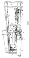
- the drawing-in machine consists of a base frame 1 and of various assemblies arranged in it, each of which represents a functional module.
- a warp beam carriage 2 with a warp beam 3 arranged on it can be seen.
- the warp beam carriage 2 is coupled via the warp beam 3 to a device, hereinafter referred to as a lifting device 4, for receiving and holding a pull-in frame 5, on which the warp threads KF are stretched.
- This clamping takes place before the actual drawing in and at a location separate from the drawing machine, the drawing frame 5 being positioned at the lower end of the lifting device 4 in the immediate vicinity of the warp beam 3.
- the warp beam carriage 2 with the warp beam 3 and lifting device 4 is moved to the so-called upgrade side of the pulling-in machine and the pulling frame 5 is lifted upwards by the lifting device 4 and suspended in the base frame 1, where he then occupies the position shown.
- the frame 5 is suspended in a transport device (not shown) mounted on the front upper longitudinal member 6 of the base frame 1.
- the frame 5 and the lifting device 4 with the warp beam carriage 2 and the warp beam 3 are shifted from left to right in the longitudinal direction of the beam 6.
- the warp threads KF are guided past a thread separating stage FT, which has a device for dividing the warp threads and for cutting off the divided warp threads KF and a device for presenting the cut warp threads to a pull-in needle 7, the latter forming part of the so-called pull-in module.
- the sectioning device used in the USTER TOPMATIC warp knitting machine can be used, for example, to separate the warp threads.
- a monitor 8 which belongs to an operating station and is used to display machine functions and machine malfunctions and for data input.
- the operating station which forms part of a so-called programming module, also contains an input stage for the manual input of certain functions, such as, for example, crawl gear, start / stop, repetition of operations, and the like.
- the drawing machine is controlled by a control module containing a control computer, which is arranged in a control box 9.
- this control box contains a module computer for each so-called main module, the individual module computers being controlled and monitored by the control computer.
- the main modules of the drawing machine are, in addition to the modules already mentioned, drawing module, yarn module, control module and programming module, the strand, the lamella and the sheet module.
- the thread separation stage FT which presents the warp threads KF to be drawn in to the pull-in needle 7, and the path of movement of the pull-in needle 7, which runs perpendicular to the plane of the stretched warp threads KF, determine a plane in the region of a support 10 forming part of the base frame, which supports the already mentioned upgrade side of the so-called disassembly side of the drawing machine.
- the warp threads and the individual elements into which the warp threads are to be fed are fed in on the upgrade side, and the so-called dishes (strands, lamellae and sheets) with the drawn-in warp threads can be removed on the tear-down side.
- the warp thread guard slats LA are arranged, behind them the healds LI and further down the reed.
- the lamellae LA are stacked in hand magazines, and the full hand magazines are hung in inclined feed rails 11, on which they are transported to the right, towards the pull-in needle 7. There they are separated and brought into the feed position. After pulling in, the slats LA arrive on slat support rails 12 on the dismantling side.
- the strands LI are lined up on rails 13 and shifted to a separating stage thereon. Then the healds LI are individually brought into their retracted position and, after they have been drawn in, distributed to the corresponding heald frames 14 on the dismantling side. The reed is also moved past the pull-in needle 7 step by step, the corresponding sheet gap being opened for the feed. After it has been drawn in, the sheet is also on the dismantling side. To the right of the heald frames 14 is a part of the reed WB. This illustration is to be understood purely for illustrative purposes, since the reed is of course located on the upgrade page in the position of the frame 5 shown.
- a so-called crockery trolley 15 is provided on the dismantling side. This is inserted together with the slat support rails 12, heald frames 14 and a holder for the reed attached to the base frame 1 in the position shown and wears the dishes with the KF warp threads drawn in after being drawn in.
- the lifting device 4 and the warp beam carriage 2 with the warp beam 3 are located directly in front of the dishwashing carriage 15. Now the tableware is reloaded from the dishwashing carriage 15 onto the warp beam carriage 2, which then carries the warp beam 3 and the pulled-in dishes and can be driven to the weaving machine in question or to an interim storage facility.
- the individual main modules of the drawing machine are made up of sub-modules, which are each intended for specific functions. However, this modular structure is not the subject of the present invention. In this context, the Int. Application No. PCT / CH90 / 00227 referenced.
- the slat conveying device takes over the slats with the warp threads drawn in and moves them on the slat support rails 12.
- the slat conveying device is arranged on the crockery trolley 15, which essentially consists of a wheeled frame which, in addition to the slat conveying device carries a heald conveyor for conveying the drawn healds on the heald frames 14 and a holder for the reed WB.
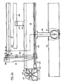
- FIGS. 2 to 4 The lamella conveying device is shown in FIGS. 2 to 4, with FIGS. 2a and 2b each showing a view in the region of the two end faces of the elongated device, namely from the rear, with reference to FIG. 1, that is to say seen from the reed WB.
- Fig. 2a shows the outer, on the right in Fig. 1
- Fig. 2b shows the inner, in Fig. 1, the left end of the slat conveyor.
- This inner end is the so-called filling side, that is to say the side on which the lamella conveyor device removes the drawn lamellae from the one in the int.
- Registration No. PCT / CH91 / 00190 sub-module described slat distribution takes over.
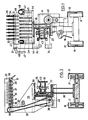
- FIG. 3 shows a section along the line A-A of Fig. 2a and Fig. 4 shows a section along the line B-B of Fig. 2b, wherein in Fig. 3 the lamella support rails are omitted for clarity.
- the scale is approximately 1: 3.5. It should be noted that FIGS. 2a and 2b show only a small part of the lamella conveyor device, the total length of which is approximately 4.5 meters.
- the lamella conveying device essentially consists of a profile carrier 16 extending over the entire length for the various holding and actuating members to be described, which is mounted on bearing blocks 18 provided with transport wheels 17 is mounted.
- the transport wheels 17 are guided in rails 19 which are mounted on the crockery trolley 15 (FIG. 1).
- the lamellar support rails 12 are placed on horizontal support rods 20, which are inserted into vertical support bolts 21 and have a round cross section with a radially projecting, beard-like comb 22.
- This comb contains equally spaced guide slots for the lamella support rails. According to the illustration, eight such slots are provided for a total of eight lamella support rails.
- the support rods 20 are provided with a handle and are held detachably and fixably in the support bolt 21, loosening and fixing being carried out by correspondingly rotating the support rods about their longitudinal axis. In the position shown in FIG. 4, the support rod 20 is fixed; to pull it out of the support pin 21, it must be rotated through 180 °, in which position the comb 21 can pass a corresponding groove 23 in the support pin 21.
- the support bolts 21 are in turn inserted at their lower end into support arms 24, which are in engagement with a transport chain 25 and can be moved by this along the profile carrier 16.
- the support arms 24 are guided during their transport in the profile carrier 16, which for this purpose has an upper and a lower guide trough 26 and 27, in which the corresponding strand of the transport chain 25 runs.
- the carrying arms 24 driven by the transport chain 25 thus perform a back and forth movement along a closed path with a working stroke and an idle stroke.
- the support arms 24 are loaded with the support bolts 21, the support rods 20 and the lamellar support rails 12 and run outwards in the upper guide trough 26 from the filling side at a speed which corresponds to the speed of the growth of the lamella stack on the lamellar support rails 12 .
- a number of support arms 24 are provided over the length of the profile beam 16; their movement is necessary to enable a continuous transport of the slats LA along the slat support rails 12.
- the support arms 24 slide along the lamella support rails 12 during their movement, leave them and finally come to their outer reversal point, where they change from the upper guide trough 26 into the lower guide trough 27.
- the support bolts 21 and the support rods 20 are removed from the support arms 24, and the support arms 24 run unloaded in the lower guide channel 27 back to the filling side, where the support bolts 21 then again with the Support rod 20 are inserted into the support arms 24. If it should be forgotten or overlooked to remove the support bolts 21 with the support rods 20 from the support arms 24 in good time, then the support bolts 21 will automatically fall out of them when the support arms 24 are changed from the upper to the lower guide channel.
- the lamella support rails 12 have at their filling-side end an inclined inlet part 28 on which the slats slide onto the support rails. At its other end, the lamella support rails 12 are guided in guide slots 29 of a retaining web 30 and are fixed to the retaining web by means of a corresponding locking pin 31 which penetrates the lamella support rails.
- This forms a projecting support on the upper crossbeam 32 of a rear wall 33 fixed to the profile support 16, on which drive means are also provided for displacing the slats on the slat support rails 12.
- the latter are constructed like a sandwich and consist of a core and two side walls projecting above and below the core, so that a U-shaped groove extending over the length of the lamella support rail 12 is formed above and below the rail forming the core.
- the actual contact or sawtooth rail KS for the warp thread monitor is held in the lower groove, onto which the slats are lined up in front of the contact or sawtooth rail by simply pulling off the slat support rail 12. In this way, it is possible for the first time to line up the slats on the warp guard rails directly on the warp guard rails, without the need for an additional operation.
- a threaded spindle 34 which is rotatable about its longitudinal axis and which acts as a means for displacement the lamellae along the lamella support rails 12 is used by the lamellae being displaced by the thread on which they are lined up when the threaded spindle 34 rotates.
- the drive of the threaded spindle 34 takes place via gear wheels 35, which have a chuck 36 for receiving the end of each threaded spindle 34, which is smooth for this purpose.
- gear wheels 35 which have a chuck 36 for receiving the end of each threaded spindle 34, which is smooth for this purpose.
- eight gearwheels 35 are provided, which are mounted on the above-mentioned upper crossbeam 32 of the rear wall 33 and are coupled to one another in terms of drive by means of intermediate gearwheels 37. By using the intermediate gears 37, all gears 35 have the same direction of rotation.
- the gear wheels 35 are in turn driven by toothed belt wheels 38 and a toothed belt 39 by a shaft 40 running along the profile support 16, which has a drive motor 41 at its end lying on the filling side of the lamella conveying device (FIG. 2b) and a drive motor 41 at its other end Reverse gear 42 is connected.
- This reversing gear mechanism in turn drives a sprocket 43 serving as a drive for the transport chain 25, so that both the conveying of the slats on the slat support rails 12 and the displacement of the organs (support rods 20, support bolts 21, support arms 24) carrying the slat support rails 12 the motor 41 takes place.
- a second sprocket 43 is arranged on the filling-side end of the lamella conveyor device.
- the shaft 40 is constructed in two parts, the two parts being connected to one another in an articulated manner, and the part following the motor 41 having a round and the other part a hexagonal cross section.
- FIGS. 2a, 2b and 4 several, preferably three or four, spaced-apart holding rails 44 are arranged on the profile carrier 16, on which holders 45 for separating rods 46 running between the rows of lamellae are mounted.
- the latter serve to separate the slats LA of adjacent rows from one another and to prevent them from touching and getting caught in one another.
- the package with the separating rods 46 is covered on both long sides by a stable protective strip 48, which is also carried by holders 47 mounted on the holding rails 44 and which protects the plate packs against external influences.
- the slat conveying device described enables the slats on the slat carrier rails to be conveyed automatically with optimally gentle treatment of the warp threads and, for the first time, enables the warp guard rails to be loaded directly on the drawing-in machine.
Landscapes
- Engineering & Computer Science (AREA)
- Textile Engineering (AREA)
- Auxiliary Weaving Apparatuses, Weavers' Tools, And Shuttles (AREA)
- Warping, Beaming, Or Leasing (AREA)
- Treatment Of Fiber Materials (AREA)
- Knitting Machines (AREA)
- Woven Fabrics (AREA)
- Decoration By Transfer Pictures (AREA)
- Polarising Elements (AREA)
- Replacing, Conveying, And Pick-Finding For Filamentary Materials (AREA)
- Looms (AREA)
- Polyesters Or Polycarbonates (AREA)
Applications Claiming Priority (2)
| Application Number | Priority Date | Filing Date | Title |
|---|---|---|---|
| CH181/91A CH682928A5 (de) | 1991-01-22 | 1991-01-22 | Vorrichtung zur Handhabung von Lamellen in einer Kettfadeneinziehmaschine. |
| CH181/91 | 1991-01-22 |
Publications (2)
| Publication Number | Publication Date |
|---|---|
| EP0496232A1 EP0496232A1 (de) | 1992-07-29 |
| EP0496232B1 true EP0496232B1 (de) | 1996-03-27 |
Family
ID=4181122
Family Applications (1)
| Application Number | Title | Priority Date | Filing Date |
|---|---|---|---|
| EP92100403A Expired - Lifetime EP0496232B1 (de) | 1991-01-22 | 1992-01-13 | Vorrichtung zur Handhabung von Lamellen in einer Kettfadeneinziehmaschine |
Country Status (12)
| Country | Link |
|---|---|
| US (1) | US5361467A (da) |
| EP (1) | EP0496232B1 (da) |
| JP (1) | JPH0559641A (da) |
| KR (1) | KR100239982B1 (da) |
| AT (1) | ATE136067T1 (da) |
| CA (1) | CA2057508A1 (da) |
| CH (1) | CH682928A5 (da) |
| DE (1) | DE59205792D1 (da) |
| DK (1) | DK0496232T3 (da) |
| ES (1) | ES2084842T3 (da) |
| PT (1) | PT100042A (da) |
| TR (1) | TR25612A (da) |
Cited By (1)
| Publication number | Priority date | Publication date | Assignee | Title |
|---|---|---|---|---|
| EP3754072B1 (de) * | 2019-06-19 | 2022-03-02 | Groz-Beckert KG | Vorrichtung zur handhabung von webgeschirrelementen und einziehmaschine |
Families Citing this family (3)
| Publication number | Priority date | Publication date | Assignee | Title |
|---|---|---|---|---|
| CH687714A5 (de) * | 1993-09-13 | 1997-01-31 | Stsubli Ag Zweigwerk Sargans | Vorrichtung zur Handhabung von Litzen fuer Kettfadeneinziehmaschinen. |
| CH687542A5 (de) * | 1993-09-13 | 1996-12-31 | Staeubli Ag Zweigwerk Sargans | Vorrichtung zur selektiven Uebergabe von Litzen. |
| EP3754071B1 (de) * | 2019-06-17 | 2022-03-30 | Groz-Beckert KG | Verfahren, vorrichtung, fahrbarer wagen und einziehmaschine |
Family Cites Families (14)
| Publication number | Priority date | Publication date | Assignee | Title |
|---|---|---|---|---|
| US1589587A (en) * | 1923-01-08 | 1926-06-22 | Barber Colman Co | Warp-drawing machine |
| US2230494A (en) * | 1939-01-03 | 1941-02-04 | Dallas Cotton Mills Company | Warp drawing apparatus and method |
| DE688493C (de) * | 1939-02-12 | 1940-02-22 | App & Maschinenfabriken Uster | Verfahren und Einrichtung zum Abteilen einzelner magnetisierbarer Glieder von einem Stapel, insbesondere von einem aus Kettenfadenwaechterlamellen bestehenden Stapel |
| GB663826A (en) * | 1943-12-24 | 1951-12-27 | Barber Colman Co | Improvements in drop wire feeding mechanisms for warp drawing machines |
| US3103056A (en) * | 1961-09-11 | 1963-09-10 | Barber Coleman Company | Warp drawing-in machine |
| US4047270A (en) * | 1974-09-04 | 1977-09-13 | Lindauer Dornier Gesellschaft Mbh. | Apparatus for separating objects |
| CH591583A5 (da) * | 1975-04-03 | 1977-09-30 | Grob & Co Ag | |
| US4038729A (en) * | 1976-10-04 | 1977-08-02 | Barber-Colman Company | Heddle selecting and positioning apparatus |
| DE3139626C2 (de) * | 1981-10-06 | 1983-10-06 | Lindauer Dornier Gmbh, 8990 Lindau | Vorrichtung zum Vereinzeln von Weblitzen, Lamellen o.dgl |
| DE3143484C2 (de) * | 1981-11-03 | 1983-09-29 | Lindauer Dornier Gmbh, 8990 Lindau | Vorrichtung zum Vereinzeln von Weblitzen oder Lamellen |
| DE3210920C1 (de) * | 1982-03-25 | 1983-09-29 | Lindauer Dornier Gmbh, 8990 Lindau | Vorrichtung zum Vereinzeln und Bereitstellen von Kettfaeden fuer das Einziehen der Kettfaeden in Weblitzen und Lamellen |
| JPS6420358A (en) * | 1987-07-10 | 1989-01-24 | Teijin Seiki Co Ltd | Heald magazine |
| JPS6420359A (en) * | 1987-07-10 | 1989-01-24 | Teijin Seiki Co Ltd | Heald transfer apparatus |
| JPH03193954A (ja) * | 1989-12-19 | 1991-08-23 | Osamu Nagao | 経糸のドロッパー挿入装置 |
-
1991
- 1991-01-22 CH CH181/91A patent/CH682928A5/de not_active IP Right Cessation
- 1991-12-17 CA CA002057508A patent/CA2057508A1/en not_active Abandoned
-
1992
- 1992-01-09 KR KR1019920000189A patent/KR100239982B1/ko not_active Expired - Fee Related
- 1992-01-10 JP JP4038871A patent/JPH0559641A/ja active Pending
- 1992-01-13 DK DK92100403.2T patent/DK0496232T3/da not_active Application Discontinuation
- 1992-01-13 DE DE59205792T patent/DE59205792D1/de not_active Expired - Fee Related
- 1992-01-13 ES ES92100403T patent/ES2084842T3/es not_active Expired - Lifetime
- 1992-01-13 EP EP92100403A patent/EP0496232B1/de not_active Expired - Lifetime
- 1992-01-13 AT AT92100403T patent/ATE136067T1/de not_active IP Right Cessation
- 1992-01-20 TR TR92/0044A patent/TR25612A/xx unknown
- 1992-01-21 US US07/822,908 patent/US5361467A/en not_active Expired - Fee Related
- 1992-01-21 PT PT100042A patent/PT100042A/pt not_active Application Discontinuation
Cited By (1)
| Publication number | Priority date | Publication date | Assignee | Title |
|---|---|---|---|---|
| EP3754072B1 (de) * | 2019-06-19 | 2022-03-02 | Groz-Beckert KG | Vorrichtung zur handhabung von webgeschirrelementen und einziehmaschine |
Also Published As
| Publication number | Publication date |
|---|---|
| US5361467A (en) | 1994-11-08 |
| KR100239982B1 (ko) | 2000-01-15 |
| DE59205792D1 (de) | 1996-05-02 |
| CH682928A5 (de) | 1993-12-15 |
| ATE136067T1 (de) | 1996-04-15 |
| CA2057508A1 (en) | 1992-07-23 |
| ES2084842T3 (es) | 1996-05-16 |
| EP0496232A1 (de) | 1992-07-29 |
| KR920014970A (ko) | 1992-08-26 |
| DK0496232T3 (da) | 1996-07-29 |
| JPH0559641A (ja) | 1993-03-09 |
| TR25612A (tr) | 1993-07-01 |
| PT100042A (pt) | 1994-03-31 |
Similar Documents
| Publication | Publication Date | Title |
|---|---|---|
| DE60313824T2 (de) | Verfahren und Vorrichtung zum automatischen Zuführen von stabförmigen Metallprofilen in Systemen zum Bearbeiten dieser Profile | |
| CH682577A5 (de) | Vorrichtung zur Handhabung von Litzen oder Lamellen in einer Kettfadeneinziehmaschine. | |
| CH687881A5 (de) | Litzensepariervorrichtung fuer Kettfadeneinziehmaschinen. | |
| EP0448957B1 (de) | Vorrichtung zum Vereinzeln von Litzen für Kettfadeneinziehmaschinen | |
| DE2127310C3 (de) | Fördereinrichtung für Flaschen oder ähnliches Fördergut | |
| DE2522970C3 (de) | Vorrichtung zum Zuführen von abgelängten Drähten zu einer Drahtverarbeitungsmaschine, insbesondere einer Gitterschweißmaschine | |
| EP0501222A1 (de) | Vorrichtung zum Einziehen von Kettfäden in ein Webblatt | |
| DE3817304A1 (de) | Transportvorrichtung fuer spulen | |
| DE2911051A1 (de) | Regallager, insbesondere fuer die lagerung von langgut | |
| EP0496232B1 (de) | Vorrichtung zur Handhabung von Lamellen in einer Kettfadeneinziehmaschine | |
| EP0646667B1 (de) | Vorrichtung zur Handhabung von Litzen für Kettfadeneinziehmaschinen | |
| EP0481183A2 (de) | Vorrichtung zum Vereinzeln von Lamellen in Kettfadeneinziehmaschinen | |
| EP0646669B1 (de) | Vorrichtung zur selektiven Übergabe von Litzen | |
| EP0510140B1 (de) | Maschine zum automatischen einziehen von kettfäden | |
| EP1012366B1 (de) | Vorrichtung zur übergabe von geschirrelementen einer webmaschine | |
| EP0479017B1 (de) | Flexibles Transportsystem für den gruppenweisen Transport von auf Trays aufgesetzten Spulen und Spulenhülsen | |
| EP0506931B1 (de) | Maschine zum automatischen einziehen von kettfäden | |
| EP0457145B1 (de) | Vorrichtung zur Handhabung von Lamellen für Kettfadeneinziehmaschinen | |
| DE10209992A1 (de) | Spinnmaschine | |
| DE2153319C3 (de) | Vorrichtung zum selbstätigen Zuführen von Querdrähten in Gitterschweißmaschinen | |
| DE1294872B (de) | Foerdervorrichtung fuer in einer kontinuierlich arbeitenden Behandlungsmaschine, z. B. einer Sterilisations- und Kuehlanlage, zu behandelnde, Lebensmittel enthaltende Dosen od. dgl. | |
| DE2547114A1 (de) | Verfahren und vorrichtung zum ueberfuehren von staeben von einer streckbank zu einem foerderer | |
| DE69803106T2 (de) | Vorrichtung zum automatischen Auswechseln des Warenbaums bei Webmaschinen | |
| DE1274975B (de) | Dungfoerdervorrichtung | |
| EP4534744A1 (de) | Automatisches vollwickel- und leerhülsentransportsystem |
Legal Events
| Date | Code | Title | Description |
|---|---|---|---|
| PUAI | Public reference made under article 153(3) epc to a published international application that has entered the european phase |
Free format text: ORIGINAL CODE: 0009012 |
|
| AK | Designated contracting states |
Kind code of ref document: A1 Designated state(s): AT BE DE DK ES FR GB IT LU NL PT SE |
|
| 17P | Request for examination filed |
Effective date: 19930121 |
|
| 17Q | First examination report despatched |
Effective date: 19941021 |
|
| RAP1 | Party data changed (applicant data changed or rights of an application transferred) |
Owner name: STAEUBLI AG |
|
| GRAA | (expected) grant |
Free format text: ORIGINAL CODE: 0009210 |
|
| AK | Designated contracting states |
Kind code of ref document: B1 Designated state(s): AT BE DE DK ES FR GB IT LU NL PT SE |
|
| REF | Corresponds to: |
Ref document number: 136067 Country of ref document: AT Date of ref document: 19960415 Kind code of ref document: T |
|
| REF | Corresponds to: |
Ref document number: 59205792 Country of ref document: DE Date of ref document: 19960502 |
|
| ITF | It: translation for a ep patent filed | ||
| REG | Reference to a national code |
Ref country code: ES Ref legal event code: FG2A Ref document number: 2084842 Country of ref document: ES Kind code of ref document: T3 |
|
| GBT | Gb: translation of ep patent filed (gb section 77(6)(a)/1977) |
Effective date: 19960501 |
|
| PG25 | Lapsed in a contracting state [announced via postgrant information from national office to epo] |
Ref country code: SE Effective date: 19960627 Ref country code: PT Effective date: 19960627 |
|
| ET | Fr: translation filed | ||
| REG | Reference to a national code |
Ref country code: DK Ref legal event code: T3 |
|
| PG25 | Lapsed in a contracting state [announced via postgrant information from national office to epo] |
Ref country code: LU Free format text: LAPSE BECAUSE OF NON-PAYMENT OF DUE FEES Effective date: 19970131 |
|
| PLBE | No opposition filed within time limit |
Free format text: ORIGINAL CODE: 0009261 |
|
| STAA | Information on the status of an ep patent application or granted ep patent |
Free format text: STATUS: NO OPPOSITION FILED WITHIN TIME LIMIT |
|
| 26N | No opposition filed | ||
| PGFP | Annual fee paid to national office [announced via postgrant information from national office to epo] |
Ref country code: DK Payment date: 19980326 Year of fee payment: 7 |
|
| PG25 | Lapsed in a contracting state [announced via postgrant information from national office to epo] |
Ref country code: DK Free format text: LAPSE BECAUSE OF NON-PAYMENT OF DUE FEES Effective date: 19990202 |
|
| PGFP | Annual fee paid to national office [announced via postgrant information from national office to epo] |
Ref country code: AT Payment date: 19991228 Year of fee payment: 9 |
|
| REG | Reference to a national code |
Ref country code: DK Ref legal event code: EBP |
|
| PGFP | Annual fee paid to national office [announced via postgrant information from national office to epo] |
Ref country code: GB Payment date: 20001221 Year of fee payment: 10 |
|
| PGFP | Annual fee paid to national office [announced via postgrant information from national office to epo] |
Ref country code: NL Payment date: 20001227 Year of fee payment: 10 |
|
| PGFP | Annual fee paid to national office [announced via postgrant information from national office to epo] |
Ref country code: BE Payment date: 20010102 Year of fee payment: 10 |
|
| PGFP | Annual fee paid to national office [announced via postgrant information from national office to epo] |
Ref country code: FR Payment date: 20010103 Year of fee payment: 10 |
|
| PG25 | Lapsed in a contracting state [announced via postgrant information from national office to epo] |
Ref country code: AT Free format text: LAPSE BECAUSE OF NON-PAYMENT OF DUE FEES Effective date: 20010113 |
|
| REG | Reference to a national code |
Ref country code: GB Ref legal event code: IF02 |
|
| PG25 | Lapsed in a contracting state [announced via postgrant information from national office to epo] |
Ref country code: GB Free format text: LAPSE BECAUSE OF NON-PAYMENT OF DUE FEES Effective date: 20020113 |
|
| PGFP | Annual fee paid to national office [announced via postgrant information from national office to epo] |
Ref country code: ES Payment date: 20020118 Year of fee payment: 11 |
|
| PG25 | Lapsed in a contracting state [announced via postgrant information from national office to epo] |
Ref country code: BE Free format text: LAPSE BECAUSE OF NON-PAYMENT OF DUE FEES Effective date: 20020131 |
|
| BERE | Be: lapsed |
Owner name: STAUBLI A.G. Effective date: 20020131 |
|
| PG25 | Lapsed in a contracting state [announced via postgrant information from national office to epo] |
Ref country code: NL Free format text: LAPSE BECAUSE OF NON-PAYMENT OF DUE FEES Effective date: 20020801 |
|
| GBPC | Gb: european patent ceased through non-payment of renewal fee |
Effective date: 20020113 |
|
| PG25 | Lapsed in a contracting state [announced via postgrant information from national office to epo] |
Ref country code: FR Free format text: LAPSE BECAUSE OF NON-PAYMENT OF DUE FEES Effective date: 20020930 |
|
| NLV4 | Nl: lapsed or anulled due to non-payment of the annual fee |
Effective date: 20020801 |
|
| REG | Reference to a national code |
Ref country code: FR Ref legal event code: ST |
|
| PG25 | Lapsed in a contracting state [announced via postgrant information from national office to epo] |
Ref country code: ES Free format text: LAPSE BECAUSE OF NON-PAYMENT OF DUE FEES Effective date: 20030114 |
|
| REG | Reference to a national code |
Ref country code: ES Ref legal event code: FD2A Effective date: 20030114 |
|
| PG25 | Lapsed in a contracting state [announced via postgrant information from national office to epo] |
Ref country code: IT Free format text: LAPSE BECAUSE OF NON-PAYMENT OF DUE FEES Effective date: 20050113 |
|
| PGRI | Patent reinstated in contracting state [announced from national office to epo] |
Ref country code: IT Effective date: 20080301 |
|
| PGFP | Annual fee paid to national office [announced via postgrant information from national office to epo] |
Ref country code: DE Payment date: 20090122 Year of fee payment: 18 |
|
| PGFP | Annual fee paid to national office [announced via postgrant information from national office to epo] |
Ref country code: IT Payment date: 20090126 Year of fee payment: 18 |
|
| PG25 | Lapsed in a contracting state [announced via postgrant information from national office to epo] |
Ref country code: DE Free format text: LAPSE BECAUSE OF NON-PAYMENT OF DUE FEES Effective date: 20100803 |
|
| PG25 | Lapsed in a contracting state [announced via postgrant information from national office to epo] |
Ref country code: IT Free format text: LAPSE BECAUSE OF NON-PAYMENT OF DUE FEES Effective date: 20100113 |