EP0496309B1 - Fahrzeug mit einem U-förmigen, hinten offenen Rahmen - Google Patents
Fahrzeug mit einem U-förmigen, hinten offenen Rahmen Download PDFInfo
- Publication number
- EP0496309B1 EP0496309B1 EP92100803A EP92100803A EP0496309B1 EP 0496309 B1 EP0496309 B1 EP 0496309B1 EP 92100803 A EP92100803 A EP 92100803A EP 92100803 A EP92100803 A EP 92100803A EP 0496309 B1 EP0496309 B1 EP 0496309B1
- Authority
- EP
- European Patent Office
- Prior art keywords
- load carrier
- shaped frame
- lifting
- vehicle
- arm
- Prior art date
- Legal status (The legal status is an assumption and is not a legal conclusion. Google has not performed a legal analysis and makes no representation as to the accuracy of the status listed.)
- Expired - Lifetime
Links
- 238000006073 displacement reaction Methods 0.000 claims abstract description 3
- 230000008878 coupling Effects 0.000 claims description 5
- 238000010168 coupling process Methods 0.000 claims description 5
- 238000005859 coupling reaction Methods 0.000 claims description 5
- 238000004519 manufacturing process Methods 0.000 abstract 1
- 230000005540 biological transmission Effects 0.000 description 2
- 239000000969 carrier Substances 0.000 description 2
- 239000007787 solid Substances 0.000 description 1
Images



Classifications
-
- B—PERFORMING OPERATIONS; TRANSPORTING
- B60—VEHICLES IN GENERAL
- B60P—VEHICLES ADAPTED FOR LOAD TRANSPORTATION OR TO TRANSPORT, TO CARRY, OR TO COMPRISE SPECIAL LOADS OR OBJECTS
- B60P1/00—Vehicles predominantly for transporting loads and modified to facilitate loading, consolidating the load, or unloading
- B60P1/48—Vehicles predominantly for transporting loads and modified to facilitate loading, consolidating the load, or unloading using pivoted arms raisable above load-transporting element
- B60P1/483—Vehicles predominantly for transporting loads and modified to facilitate loading, consolidating the load, or unloading using pivoted arms raisable above load-transporting element using pivoted arms shifting the load-transporting element in a fore or aft direction
-
- B—PERFORMING OPERATIONS; TRANSPORTING
- B60—VEHICLES IN GENERAL
- B60P—VEHICLES ADAPTED FOR LOAD TRANSPORTATION OR TO TRANSPORT, TO CARRY, OR TO COMPRISE SPECIAL LOADS OR OBJECTS
- B60P1/00—Vehicles predominantly for transporting loads and modified to facilitate loading, consolidating the load, or unloading
- B60P1/64—Vehicles predominantly for transporting loads and modified to facilitate loading, consolidating the load, or unloading the load supporting or containing element being readily removable
- B60P1/6418—Vehicles predominantly for transporting loads and modified to facilitate loading, consolidating the load, or unloading the load supporting or containing element being readily removable the load-transporting element being a container or similar
- B60P1/6427—Vehicles predominantly for transporting loads and modified to facilitate loading, consolidating the load, or unloading the load supporting or containing element being readily removable the load-transporting element being a container or similar the load-transporting element being shifted horizontally in a fore and aft direction, combined or not with a vertical displacement
Definitions
- the present invention relates to a vehicle having a drive unit and a U-shaped and rearwardly open frame comprising a web member which is fixedly connected with the driving unit, said vehicle being adapted to move backwards relative to a load carrier until said load carrier is situated within the shanks of said U-shaped frame and adapted to lift said load carrier from the ground for transportation thereof after lifting and whereby the U-shaped frame includes a lifting unit having such vertically movable lifting arms that said arms can
- This prior art vehicle includes a lifting and tilting device for lifting and tilting the load carrier.
- This lifting and tilting device comprises two cylinder/plunger devices and two support rails provided thereon. During lifting and lowering, the cylinder/plunger devices are pivoted and displace the support rails and thus, the load carrier in a forward or backward direction relative to the U-shaped frame.
- said cylinder/plunger devices are pivotally mounted such that they during the lifting and lowering movements displace the load carrier a substantial distance in a direction along the vehicle. This is also inappropriate if the load carrier is heavily loaded, while then, the load is displaced relative to the vehicle and tilting of the vehicle might occur under unfavourable circumstances.
- a vehicle having another type of lifting device is known from FR-A-2 106 120.
- This prior art vehicle is a trailer with a lifting device in the form of two pairs of crossed lifting arms which are pivoted relative to each other in a scissors-like manner by means of cylinder/plunger devices for lifting and lowering a load carrier.
- This prior art lifting device is neither suitable for handling heavy loads, since it is much too weak, generates too small a lifting force and also at least to some extent displaces the load carrier in a backward or forward direction during lifting and lowering, which at worst might cause tilting of the trailer.
- the object of the present invention is to provide a lifting unit at vehicles of the abovementioned type, which permits safe handling also of very heavy load carriers. This is arrived at according to the invention by means of the characterizing features of claim 1.
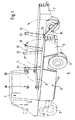
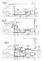
- the vehicle illustrated in the drawings comprises a drive unit 1 with the driving compartment of the vehicle as well as the front wheels 2 and a rear part including a U-shaped and rearwardly open frame 3 as well as rear wheels 4 provided thereon.
- the vehicle is adapted to move backwards relative to a load carrier 5, e.g. a container, until said load carrier is situated within the shanks 6 and 7 of said U-shaped frame 3 and preferably adjacent the web member 8 of said frame.
- the vehicle is also adapted to lift the load carrier 5 from the ground 9 and to transport said load carrier after lifting thereof.
- the U-shaped frame 3 is through its web member 8 immovably mounted in vertical direction on the part of the vehicle situated in front of said frame, i.e. at the driving compartment 1 or to another member connected with said driving compartment.
- a lifting unit 10 having such vertically movable lifting arms 11-14 that said arms can
- the lifting unit 10 may comprise two fore or front lifting arms 11, 12 and two rear lifting arms 13, 14.
- the fore lifting arm 11 is mounted on the shank 6 and the other fore lifting arm 12 on the shank 7. Both said fore lifting arms 11, 12 are preferably pivotable about horizontal axes 15 in an upward / backward direction from lower grip po-sitions A to transport positions B and further upwards / backwards to upper positions C.
- One rear lifting arm 13 of the lifting unit 10 is mounted on the shank 6 and the rear lifting arm 14 on the shank 7. Both of these rear lifting arms 13, 14 are preferably pivotable about horizontal axes 16 in an upward / forward direction from lower grip positions A to transport positions B and further upwards / forward to upper positions C.
- the vertically movable lifting arms 11-14 are pivotally mounted in such a manner that they can move the load carrier 5 in a vertical direction or a substantially vertical direction without substantial displacement in longitudinal direction and/or without substantial tilting relative to the U-shaped frame 3.
- the lifting unit 10 further comprises two cylinder / plunger devices 17, 18 for operating the lifting arms 11-14.
- One cylinder / plunger device 17 is preferably built into the shank 6 and the plunger means 19 thereof preferably, through a power transmission arm 21, articulately connected with both said lifting arms 11, 13 such that the cylinder / plunger device 17 can swing or pivot these lifting arms simultaneously so that their swinging or pivoting movements depend on each other.
- the other cylinder / plunger device 18 is preferably built into the shank 7 and the plunger means 20 thereof is preferably, through a power transmission arm 22, articulately connected with both said lifting arms 12. 14 in such a manner that said cylinder / plunger device 18 can swing or pivot these lifting arms 12, 14 simulataneously and with swinging or pivoting movements that depend on each other.
- Each lifting arm has at its outer end a preferably inwardly directed lifting pin 23, which is adapted to be brought into engagement with connecting means 24-27 on the load carrier 5.
- Each lifting pin 23 can include a rotatably mounted roller 23a.
- Two fore connecting means 24, 25 are provided at the front on opposite sides of the load carrier 5 in such a way that the fore lifting arms 11, 12 can be brought to cooperate therewith.
- Two rear connecting means 26, 27 are provided on opposite sides of the load carrier 5 behind the fore connecting means 24, 25 and in such a way that the rear lifting arms 13, 14 can be brought to cooperate therewith.
- Each connecting means 24, 27 has an upper, horizontally or substantially horizontally extending flange 28 and a lower, horizontally or substantially horizontally extending flange 29 and these flanges define together a horizontally or substantially horizontally extending groove 30 for the lifting pin 23 and its roller 23a.
- the lower flange has an aperture 31 through which the lifting pin 23 can be moved up and into the groove 30 until the roller 23a of said pin 23 engages the bottom or lower side of the upper flange 28.
- the aperture 31 is preferably located at the front in the lower flange 29 and at the rear connecting means 26, 27 the aperture 31 is preferably located at the back in said lower flange 29.
- the lifting arms 11-14 are swung upwards, whereby the lifting pins 23 thereof slide into the grooves 30 of the connecting means 24-27 through the apertures 31 and said grooves 30 are preferably only some what wider than the diameter of the rollers 23a of said lifting pins 23.
- the lifting unit 10 starts to lift the load carrier 5 from the ground 9 and by further swinging or pivoting of the lifting arms 11-14 in upward direction, i.e.
- the lifting pins 23 and the rollers 23a on the fore lifting arms 11, 12 will move backwards in the grooves 30 of the fore connecting means 24, 25 and the lifting pins 23 and rollers 23a on the rear lifting arms 13, 14 will move forward in the grooves 30 of the rear connecting means 26, 27.
- the load carrier 5 can not move in vertical direction relative to the lifting pins 23 in an unsuitable manner when said load carrier is lifted, lowered, held in lifted position or transported.
- the load carrier 5 When the lifting arms 11-14 are swung in opposite direction, the load carrier 5 is lowered and can be placed on the ground 9, whereby the lifting unit 10 is released by swinging the lifting arms 11-14 to position A, and during this downward swinging or pivoting movement, the lifting pins 23 will disengage the connecting means 24-27.
- said connecting means 24-27 of the load carrier 5 are located on a level substantially above the bottom or lower side 32 of said load carrier 5.
- said load carrier can be locked in this transport position T relative to the frame 3 by locking said lifting unit 10 against movement and/or by bringing a lock device (not shown) on the frame 3 in locking engagement with the load carrier 5 or members provided thereon.
- the transport position T of the load carrier 5 is preferably chosen so that said load carrier thereby is positioned with its bottom or lower side 32 in level with the bottom or lower side 33 of the frame 3 or at any level between the lower side 33 and top or upper side 34 of said frame 3.
- the lifting unit 10 can lift the load carrier 5 to such upper positions C that said load carrier is placed substantially above the upper side 34 of the U-shaped frame 3.
- the load carrier 5 can be lifted to the level of a loading platform 35 (see fig. 6), from where a load can be unloaded or loaded into said load carrier 5.
- said load carrier 5 is provided with grip portions 36, 37 which can cooperate with guide portions 38, 39 on the vehicle.
- the grip portions 36, 37 are preferably provided on a side of the load carrier 5 which is facing forward when said load carrier is situated in the frame 3 and the guide portions 38, 39 are preferably provided on the vehicle behind the driving compartment 1 and most preferably on the rear side thereof.
- Each grip portion 36, 37 may comprise an elongated guide rail 40 (see fig. 7) in the shape of a square tube with a longitudinal slit 41.
- Each guide portion 38, 39 may include a pin 42 which is provided on the driving compartment 1 and which on its free end has an expanding guide member 43.
- the pin 42 is dimensioned such that it can protrude into the guide rail through the slit 41 therein and the guide member 43 is dimensioned such that it fits into the interior of said guide rail 40.
- grip portions 36, 37 and guide portions 38, 39 are also mounted such that the guide rail 40 slides onto the guide member 43 when the lifting unit 10 lifts the load carrier 5 from the ground 9 and said guide rail 40 maintains its grip or engagement with said guide member 43 during the lifting and lowering movements and as long as said load carrier 5 is lifted from the ground 9.
- each lifting arm 11-14 is at the bottom longitudinally displaceably mounted in the respective shank 6, 7, while it at the top is connectable to the load carrier 5 without being displaceable in relation thereto.
- each lifting arm 11-14 has at the bottom a pivot (not shown) which is inserted into and engages a guide groove 44 provided in a guide rail 45 on the respective shank 6, 7 and which extends in longitudinal direction of said respective shank.
- Each lifting arm 11-14 is also con-nected with the respective shank 6, 7 through a guide arm 46 which is pivotally mounted on the shank and pivotally provided on the respective lifting arm at a distance above its pivot, through which it is mounted in the guide groove 44.
- the respective guide arm 46 operates or controls the respective lifting arm 11-14 to raise or lower in such a way that the respective upper coupling members 47 on the respective lifting arm 11-14 move straight up and down in vertical direction.
- a load carrier 5 engaged by the lifting arms 11-14 will be lifted or lowered linearly without at the same time being displaced further on or further backwards relative to the frame 3 nor tilted in relation thereto.
- the coupling members 47 can be insertable from below into coupling members (not shown) therefor in the load carrier 5, such that said load carrier can not move relative to said coupling members in the longitudinal direction of the frame 3.
Landscapes
- Engineering & Computer Science (AREA)
- Transportation (AREA)
- Mechanical Engineering (AREA)
- Automatic Cycles, And Cycles In General (AREA)
- Body Structure For Vehicles (AREA)
- Handcart (AREA)
- Fittings On The Vehicle Exterior For Carrying Loads, And Devices For Holding Or Mounting Articles (AREA)
- Loading Or Unloading Of Vehicles (AREA)
- Forklifts And Lifting Vehicles (AREA)
- Carriers, Traveling Bodies, And Overhead Traveling Cranes (AREA)
- Auxiliary Methods And Devices For Loading And Unloading (AREA)
Claims (6)
- Fahrzeug mit einem Antrieb (1) und einem U-förmigen, hinten offenen Rahmen (3), der einen mit dem Antrieb (1) fest verbundenen Steg (8) aufweist, wobei das Fahrzeug vorgesehen ist, im Verhältnis zu einem Lastträger (5) rückwärts bewegt zu werden, bis sich der Lastträger innerhalb der Längsträger (6, 7) des U-förmigen Rahmens befindet, und weiterhin vorgesehen ist, den Lastträger (5) von dem Boden (9) hochzuheben zum Transport des Lastträgers nach dessen Hochheben, und wobei der U-förmige Rahmen (3) mit einer Hebevorrichtung (10) versehen ist, die solche senkrecht bewegliche Hebearme (11-14) besitzt, dass die genannten Armea) mit dem Lastträger (5) eingreifen können, wenn der Lastträger auf dem Boden (9) innerhalb der Längsträger (6, 7) des U-förmigen Rahmens (3) steht;b) den Lastträger (5) von dem Boden (9) in eine Transportstellung (T) hochheben können, in welcher der Lastträger im Verhältnis zu dem U-förmigen Rahmen (3) verriegelbar ist und in welcher das Fahrzeug den Lastträger transportieren kann; undc) den Lastträger (5) über die Transportstellung (T) hinauf in eine oder mehrere Stellungen (L) hochheben können, in denen sich der Lastträger in einer zweckmässigen Höhenlage zum Laden oder Entladen befindet;dadurch gekennzeichnet, dass
zwei senkrecht bewegliche Hebearme (11, 13) an der Innenseite des einen Längsträgers (6) des U-förmigen Rahmens (3) und zwei andere senkrecht bewegliche Hebearme (12, 14) an der Innenseite des anderen Längsträgers (7) des U-förmigen Rahmens angeordnet sind;
dass ein unteres Ende jedes Hebearms (11-14) im Verhältnis zu dem bezüglichen Längsträger (6, 7) längsverschiebbar montiert ist;
dass jeder Hebearm (11, 14) mit dem bezüglichen Längsträger (6, 7) mittels eines Führungsarms (46) verbunden ist, welcher an dem Hebearm (11-14) und an dem bezüglichen Längsträger (6, 7) schwenkbar montiert ist; und
dass das untere Ende jedes Hebearms (11, 14) im Verhälnis zu dem Längsträger (6, 7) mittels einer Zylinder/Kolbenvorrichtung (17, 18) versetzbar ist,
wodurch der bezügliche Führungsarm (46) den bezüglichen Hebearm (11-14) steuert, um den Lastträger (5) in senkrechte oder hauptsächlich senkrechte Richtung zu bewegen, und zwar ohne wesentliche Versetzung desselben in der Längsrichtung und/oder ohne wesentliches Kippen desselben gegenüber dem U-förmigen Rahmen (3). - Fahrzeug nach Anspruch 1, dadurch gekennzeichnet, dass das untere Ende jedes Hebearms (11-14) mit einem Zapfen versehen ist, der in eine Führungsnut (44) einer Führungsschiene (45) an der Innenseite des unteren Teils des bezüglichen Längsträgers (6, 7) eingreift.
- Fahrzeug nach Anspruch 1 oder 2, dadurch gekennzeichnet, dass die Zylinder/Kolbenvorrichtung (17, 18) mit dem bezüglichen Hebearm (11-14) in einem Punkt oberhalb einer Verbindung zwischen dem Hebearm (11-14) und dem Führungsarm (46) verbunden ist.
- Fahrzeug nach irgendeinem der vorhergehenden Ansprüche, dadurch gekennzeichnet, dass jeder Hebearm (11-14) durch einen oberen Kupplungsteil (47) derart mit dem Lastträger (5) verbunden werden kann, dass der Lastträger bei dessen Hochheben oder Herabsenken nicht in der Längsrichtung des U-förmigen Rahmens (3) versetzt wird.
- Fahrzeug nach irgendeinem der vorhergehenden Ansprüche, dadurch gekennzeichnet, dass der Lastträger (5) im Verhältnis zu dem U-förmigen Rahmen (3) in einer Transportstellung (T) verriegelbar ist, in welcher der Boden oder die Unterseite (32) des Lastträgers auf gleicher Höhe mit dem Boden oder der Unterseite (33) des U-förmigen Rahmens oder auf irgendwelcher Höhe zwischen der Unterseite (33) und der Oberseite (34) des U-förmigen Rahmens liegt und dass der Lastträger (5) mittels der Hebearme (11-14) in Höhenlagen hochgehoben werden kann, in denen die Unterseite (32) des Lastträgers im wesentlichen oberhalb der Oberseite (34) des U-förmigen Rahmens (3) liegt.
- Fahrzeug nach irgendeinem der vorhergehenden Ansprüche, dadurch gekennzeichnet, dass der Antrieb (1) des Fahrzeugs ein Fahrerhaus sowie Motor und Vorderräder (2) umfasst und dass die Hinterräder (4) des Fahrzeugs hinten an den Längsträgern (6, 7) des U-förmigen Rahmens (3) angebracht sind.
Applications Claiming Priority (2)
| Application Number | Priority Date | Filing Date | Title |
|---|---|---|---|
| SE9100224A SE502329C2 (sv) | 1991-01-25 | 1991-01-25 | Fordon med en U-formad och bakåt öppen ram |
| SE9100224 | 1991-01-25 |
Publications (2)
| Publication Number | Publication Date |
|---|---|
| EP0496309A1 EP0496309A1 (de) | 1992-07-29 |
| EP0496309B1 true EP0496309B1 (de) | 1995-06-21 |
Family
ID=20381709
Family Applications (1)
| Application Number | Title | Priority Date | Filing Date |
|---|---|---|---|
| EP92100803A Expired - Lifetime EP0496309B1 (de) | 1991-01-25 | 1992-01-20 | Fahrzeug mit einem U-förmigen, hinten offenen Rahmen |
Country Status (7)
| Country | Link |
|---|---|
| EP (1) | EP0496309B1 (de) |
| JP (1) | JPH04310439A (de) |
| AT (1) | ATE124003T1 (de) |
| DE (1) | DE69202989T2 (de) |
| DK (1) | DK0496309T3 (de) |
| ES (1) | ES2076565T3 (de) |
| SE (1) | SE502329C2 (de) |
Cited By (1)
| Publication number | Priority date | Publication date | Assignee | Title |
|---|---|---|---|---|
| EP4620732A1 (de) * | 2024-03-19 | 2025-09-24 | Scrapskrot AB | Transportfahrzeug mit rückwärts offenem fahrgestell |
Families Citing this family (7)
| Publication number | Priority date | Publication date | Assignee | Title |
|---|---|---|---|---|
| US5906419A (en) * | 1995-12-07 | 1999-05-25 | Tooling Technology Centre, Inc. | Wheel mounting assembly for installing a transmission-based anti-lock braking system sensor thereon |
| US6547314B1 (en) * | 2000-08-11 | 2003-04-15 | Happijac Company | Camper anchoring and/or positioning system |
| US8182193B2 (en) * | 2008-10-28 | 2012-05-22 | Max-Atlas | Trailer for transporting freight containers and method of use |
| CN106515538A (zh) * | 2017-01-17 | 2017-03-22 | 王孺牛 | 可控制车厢上下移动的机动车辆 |
| DE102018004209B4 (de) | 2018-05-25 | 2020-12-10 | Flexette Gmbh | Fahrzeug mit Fahrmodul und Lastmodul |
| JP7196822B2 (ja) * | 2019-11-19 | 2022-12-27 | トヨタ自動車株式会社 | 分離型車両 |
| CN115605368A (zh) | 2020-04-30 | 2023-01-13 | Dipp-R公司(Se) | 用于电动车辆和货箱的供电系统 |
Family Cites Families (4)
| Publication number | Priority date | Publication date | Assignee | Title |
|---|---|---|---|---|
| DE2044976C3 (de) * | 1970-09-11 | 1973-10-25 | Maschinenfabrik Fahr Ag Gottmadingen, 7702 Gottmadingen | Fahrzeug, insbesondere land wirtschaftliches Fahrzeug |
| DE7133433U (de) * | 1971-09-02 | 1971-12-16 | Sauer L | Fahrzeug zum Aufnehmen, Fahren, Kippen und Absetzen von Behältern |
| IT1046022B (it) * | 1973-09-27 | 1980-06-30 | Duvia Crazio | Perfezionamenti nel sistema meccanico fluidodinamico di comando del cassone di mezzi di trasporto atti a permettere il ribaltamento in posizione sollevata del cassone stesso,la sua posa a terra e rica rica sul mezzo |
| AU3613478A (en) * | 1977-05-24 | 1979-11-22 | Davis D J | Container transporter |
-
1991
- 1991-01-25 SE SE9100224A patent/SE502329C2/sv unknown
-
1992
- 1992-01-20 AT AT92100803T patent/ATE124003T1/de not_active IP Right Cessation
- 1992-01-20 ES ES92100803T patent/ES2076565T3/es not_active Expired - Lifetime
- 1992-01-20 EP EP92100803A patent/EP0496309B1/de not_active Expired - Lifetime
- 1992-01-20 DK DK92100803.3T patent/DK0496309T3/da active
- 1992-01-20 DE DE69202989T patent/DE69202989T2/de not_active Expired - Lifetime
- 1992-01-24 JP JP4011280A patent/JPH04310439A/ja active Pending
Cited By (1)
| Publication number | Priority date | Publication date | Assignee | Title |
|---|---|---|---|---|
| EP4620732A1 (de) * | 2024-03-19 | 2025-09-24 | Scrapskrot AB | Transportfahrzeug mit rückwärts offenem fahrgestell |
Also Published As
| Publication number | Publication date |
|---|---|
| DK0496309T3 (da) | 1995-10-30 |
| DE69202989D1 (de) | 1995-07-27 |
| SE9100224D0 (sv) | 1991-01-25 |
| EP0496309A1 (de) | 1992-07-29 |
| ES2076565T3 (es) | 1995-11-01 |
| ATE124003T1 (de) | 1995-07-15 |
| SE9100224L (sv) | 1992-07-26 |
| SE502329C2 (sv) | 1995-10-02 |
| JPH04310439A (ja) | 1992-11-02 |
| DE69202989T2 (de) | 1996-02-22 |
Similar Documents
| Publication | Publication Date | Title |
|---|---|---|
| US4065012A (en) | Low lift truck | |
| US2792079A (en) | Material handling apparatus | |
| US3666127A (en) | Cargo handling apparatus | |
| JPS63502175A (ja) | パレタイズド積荷を特に高速移送する荷物移送装置 | |
| US3521780A (en) | Truck-mounted lifting device | |
| US4755097A (en) | Device for the handling and transfer of a load on a vehicle such as a container or a tray | |
| CA2133049C (en) | Loading and unloading system for motor vehicle transporter | |
| US5028198A (en) | Collapsible full reach truck bed hoist | |
| US4613272A (en) | Method of operation for loading a motorized floor truck and support carriage therefor | |
| GB2104052A (en) | Handling storage units, e.g. pallets | |
| US3520429A (en) | Transport vehicle for heavy loads | |
| US4352625A (en) | Container handling apparatus | |
| EP0496309A1 (de) | Fahrzeug mit einem U-förmigen, hinten offenen Rahmen | |
| US3144149A (en) | Transporting equipment for containers | |
| EP0378379B1 (de) | Verfahren und Ausrüstung für die Be- und Entladung von Motorfahrzeugen aus Leichtbautragevorrichtungen, die auf Standardcontainern befestigt sind | |
| EP0040513B1 (de) | Anhänger | |
| US3563401A (en) | Hinged overhead guard for truck | |
| US4208160A (en) | Device for transferring load units | |
| US3768671A (en) | Loading device | |
| US4652201A (en) | Load-carrying vehicles | |
| EP0509028A1 (de) | Wagen zum heben und versetzen von behältern und verfahren zu dessen verwendung. | |
| CN109501843A (zh) | 用于搬运周转箱的搬运车 | |
| EP0163621B1 (de) | Klappbarer und verstellbarer Stützfuss für einen Lasttragerahmen | |
| CA3198545A1 (en) | An access station for an automated storage and retrieval system with container tilt functionality and a method for using same | |
| US4541766A (en) | Device for handling packs of elongated articles, especially lumber packs |
Legal Events
| Date | Code | Title | Description |
|---|---|---|---|
| PUAI | Public reference made under article 153(3) epc to a published international application that has entered the european phase |
Free format text: ORIGINAL CODE: 0009012 |
|
| AK | Designated contracting states |
Kind code of ref document: A1 Designated state(s): AT BE CH DE DK ES FR GB IT LI NL SE |
|
| 17P | Request for examination filed |
Effective date: 19921222 |
|
| 17Q | First examination report despatched |
Effective date: 19940201 |
|
| GRAA | (expected) grant |
Free format text: ORIGINAL CODE: 0009210 |
|
| AK | Designated contracting states |
Kind code of ref document: B1 Designated state(s): AT BE CH DE DK ES FR GB IT LI NL SE |
|
| REF | Corresponds to: |
Ref document number: 124003 Country of ref document: AT Date of ref document: 19950715 Kind code of ref document: T |
|
| REF | Corresponds to: |
Ref document number: 69202989 Country of ref document: DE Date of ref document: 19950727 |
|
| ITF | It: translation for a ep patent filed | ||
| ET | Fr: translation filed | ||
| REG | Reference to a national code |
Ref country code: DK Ref legal event code: T3 |
|
| REG | Reference to a national code |
Ref country code: ES Ref legal event code: FG2A Ref document number: 2076565 Country of ref document: ES Kind code of ref document: T3 |
|
| PLBE | No opposition filed within time limit |
Free format text: ORIGINAL CODE: 0009261 |
|
| STAA | Information on the status of an ep patent application or granted ep patent |
Free format text: STATUS: NO OPPOSITION FILED WITHIN TIME LIMIT |
|
| 26N | No opposition filed | ||
| REG | Reference to a national code |
Ref country code: GB Ref legal event code: IF02 |
|
| PGFP | Annual fee paid to national office [announced via postgrant information from national office to epo] |
Ref country code: DK Payment date: 20100114 Year of fee payment: 19 Ref country code: ES Payment date: 20100128 Year of fee payment: 19 Ref country code: CH Payment date: 20100113 Year of fee payment: 19 |
|
| PGFP | Annual fee paid to national office [announced via postgrant information from national office to epo] |
Ref country code: IT Payment date: 20100118 Year of fee payment: 19 Ref country code: FR Payment date: 20100208 Year of fee payment: 19 |
|
| PGFP | Annual fee paid to national office [announced via postgrant information from national office to epo] |
Ref country code: GB Payment date: 20100120 Year of fee payment: 19 Ref country code: DE Payment date: 20100114 Year of fee payment: 19 Ref country code: BE Payment date: 20100125 Year of fee payment: 19 Ref country code: AT Payment date: 20100113 Year of fee payment: 19 |
|
| PGFP | Annual fee paid to national office [announced via postgrant information from national office to epo] |
Ref country code: NL Payment date: 20100101 Year of fee payment: 19 |
|
| PGFP | Annual fee paid to national office [announced via postgrant information from national office to epo] |
Ref country code: SE Payment date: 20100108 Year of fee payment: 19 |
|
| BERE | Be: lapsed |
Owner name: *ALM LARS-GORAN Effective date: 20110131 |
|
| REG | Reference to a national code |
Ref country code: NL Ref legal event code: V1 Effective date: 20110801 |
|
| REG | Reference to a national code |
Ref country code: DK Ref legal event code: EBP |
|
| REG | Reference to a national code |
Ref country code: CH Ref legal event code: PL |
|
| REG | Reference to a national code |
Ref country code: SE Ref legal event code: EUG |
|
| GBPC | Gb: european patent ceased through non-payment of renewal fee |
Effective date: 20110120 |
|
| REG | Reference to a national code |
Ref country code: FR Ref legal event code: ST Effective date: 20110930 |
|
| PG25 | Lapsed in a contracting state [announced via postgrant information from national office to epo] |
Ref country code: FR Free format text: LAPSE BECAUSE OF NON-PAYMENT OF DUE FEES Effective date: 20110131 Ref country code: CH Free format text: LAPSE BECAUSE OF NON-PAYMENT OF DUE FEES Effective date: 20110131 Ref country code: LI Free format text: LAPSE BECAUSE OF NON-PAYMENT OF DUE FEES Effective date: 20110131 |
|
| PG25 | Lapsed in a contracting state [announced via postgrant information from national office to epo] |
Ref country code: AT Free format text: LAPSE BECAUSE OF NON-PAYMENT OF DUE FEES Effective date: 20110120 Ref country code: GB Free format text: LAPSE BECAUSE OF NON-PAYMENT OF DUE FEES Effective date: 20110120 Ref country code: BE Free format text: LAPSE BECAUSE OF NON-PAYMENT OF DUE FEES Effective date: 20110131 |
|
| PG25 | Lapsed in a contracting state [announced via postgrant information from national office to epo] |
Ref country code: IT Free format text: LAPSE BECAUSE OF NON-PAYMENT OF DUE FEES Effective date: 20110120 Ref country code: NL Free format text: LAPSE BECAUSE OF NON-PAYMENT OF DUE FEES Effective date: 20110801 |
|
| REG | Reference to a national code |
Ref country code: ES Ref legal event code: FD2A Effective date: 20120220 |
|
| REG | Reference to a national code |
Ref country code: DE Ref legal event code: R119 Ref document number: 69202989 Country of ref document: DE Effective date: 20110802 |
|
| PG25 | Lapsed in a contracting state [announced via postgrant information from national office to epo] |
Ref country code: ES Free format text: LAPSE BECAUSE OF NON-PAYMENT OF DUE FEES Effective date: 20110121 |
|
| PG25 | Lapsed in a contracting state [announced via postgrant information from national office to epo] |
Ref country code: SE Free format text: LAPSE BECAUSE OF NON-PAYMENT OF DUE FEES Effective date: 20110121 |
|
| PG25 | Lapsed in a contracting state [announced via postgrant information from national office to epo] |
Ref country code: DE Free format text: LAPSE BECAUSE OF NON-PAYMENT OF DUE FEES Effective date: 20110802 |