EP0496498A2 - Emetteur-récepteur radio pour duplex temporel - Google Patents
Emetteur-récepteur radio pour duplex temporel Download PDFInfo
- Publication number
- EP0496498A2 EP0496498A2 EP92300169A EP92300169A EP0496498A2 EP 0496498 A2 EP0496498 A2 EP 0496498A2 EP 92300169 A EP92300169 A EP 92300169A EP 92300169 A EP92300169 A EP 92300169A EP 0496498 A2 EP0496498 A2 EP 0496498A2
- Authority
- EP
- European Patent Office
- Prior art keywords
- frequency
- signal
- dividing
- reception
- transmission
- Prior art date
- Legal status (The legal status is an assumption and is not a legal conclusion. Google has not performed a legal analysis and makes no representation as to the accuracy of the status listed.)
- Withdrawn
Links
Images


Classifications
-
- H—ELECTRICITY
- H04—ELECTRIC COMMUNICATION TECHNIQUE
- H04M—TELEPHONIC COMMUNICATION
- H04M1/00—Substation equipment, e.g. for use by subscribers
- H04M1/72—Mobile telephones; Cordless telephones, i.e. devices for establishing wireless links to base stations without route selection
- H04M1/725—Cordless telephones
- H04M1/72502—Cordless telephones with one base station connected to a single line
-
- H—ELECTRICITY
- H04—ELECTRIC COMMUNICATION TECHNIQUE
- H04B—TRANSMISSION
- H04B1/00—Details of transmission systems, not covered by a single one of groups H04B3/00 - H04B13/00; Details of transmission systems not characterised by the medium used for transmission
- H04B1/38—Transceivers, i.e. devices in which transmitter and receiver form a structural unit and in which at least one part is used for functions of transmitting and receiving
- H04B1/40—Circuits
- H04B1/54—Circuits using the same frequency for two directions of communication
- H04B1/56—Circuits using the same frequency for two directions of communication with provision for simultaneous communication in two directions
-
- H—ELECTRICITY
- H04—ELECTRIC COMMUNICATION TECHNIQUE
- H04L—TRANSMISSION OF DIGITAL INFORMATION, e.g. TELEGRAPHIC COMMUNICATION
- H04L5/00—Arrangements affording multiple use of the transmission path
- H04L5/14—Two-way operation using the same type of signal, i.e. duplex
- H04L5/1469—Two-way operation using the same type of signal, i.e. duplex using time-sharing
- H04L5/1484—Two-way operation using the same type of signal, i.e. duplex using time-sharing operating bytewise
- H04L5/1492—Two-way operation using the same type of signal, i.e. duplex using time-sharing operating bytewise with time compression, e.g. operating according to the ping-pong technique
Definitions
- the present invention relates to a radio transceiver which makes a duplex radio communication by alternately making transmission and reception on a time division basis by use of the same frequency.
- TDD time-division duplex
- pingpong a method of alternately making transmission and reception in a time division fashion.
- This system has advantages that a restriction imposed on frequency allotment is less since the same frequency is used for both transmission and reception and that a high control efficiency is obtained since all interferences between transmission and reception can be monitored even in the case where a dynamic channel selection is made.
- the transmission frequency and the reception frequency of one of opposing radio stations has a reverse relation with respect to the transmission frequency and the reception frequency of the other radio station. Therefore, two kinds of equipments are required and a relation of parent and child is resulted in between the two kinds of equipments.
- the TDD system is an excellent system in which the same construction can be used in both of opposing radio equipments and a communication between child equipments is also possible.
- the TDD system since the transmission frequency and the reception frequency are the same, the TDD system has an advantage that even one equipment is not provided with a diversity circuit, a pseudo diversity effect can be expected if the other equipment is provided with two antennae and makes transmission by use of one of the two antennae which exhibits a better characteristic in a reception state.
- the TDD system is applicable not only to a duplex operation by the time division multiplexing of a single radio-wave channel but also to a time-division multiple-access (TDMA) communication in which a plurality of communications are made on the time division basis.
- TDMA time-division multiple-access
- the optimization of the TDD system for use for digital codeless telephone sets in offices having a large traffic can be realized as a TDMA/TDD system by arranging the transmission and reception timings alternately with a modulation rate twice as high as that in the two-frequency duplex system.
- the oscillation at the transmission frequency or a frequency in the vicinity is maintained in the transceiver in the reception state, and deterioration of reception sensitivity due to the transmission wave is prevented by cutting off a power source for a part of circuit or shielding the same.
- the countermeasure such as shielding has limitations in its performance. Also, if the frequency of the oscillator is shifted to an adjacent channel in the reception state to prevent the deterioration of reception sensitivity, there is a problem of causing interference in other transceivers or equipments of the same kind making communications in the neighborhood.
- An object of the present invention made to solve the above problems in the conventional art is to provide a time-division duplex radio transceiver which satisfactorily exhibits the inherent performance of a TDD system without stopping an oscillator.
- Another object of the present invention is to avoid the deterioration of reception sensitivity and the interference in other communication equipments which may be caused by the generation of a radio wave at a transmission frequency or a frequency in the vicinity when the tranceiver is in its reception state.
- a further object of the present invention is to provide a time-division duplex radio transceiver in which a receiver portion includes at least one stage of superheterodyne converter.
- a still further object of the present invention is to provide a time-division duplex radio transceiver which is capable of making a communication through a frequency change-over in a plurality of carrier frequencies.
- a signal at a transmission frequency to be emitted in the transmission state is generated by an oscillator oscillating at a frequency higher than the transmission frequency, an output of the oscillator being frequency-divided by frequency divider means, and in the reception state, an operation of the frequency divider means is stopped or a change-over to another frequency divider means is made, thereby to prevent the radio wave at the transmission frequency from being generated in the transceiver.
- a receiver portion includes at least one stage of superheterodyne frequency converter.
- the output of the oscillator is frequency-divided at different division ratios for the transmission and reception states, respectively, through a change-over therebetween, thereby obtaining the signal at the transmission frequency or the local oscillation frequency.
- a second oscillator oscillating at a local oscillation frequency for converting the intermediate frequency in the transmission state into the carrier signal at the transmission frequency higher than that and converting a signal at a reception frequency in the reception state into an intermediate frequency lower than that.
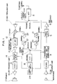
- Fig. 1 shows the construction of a first embodiment of the present invention or a block diagram of a TDD radio transceiver which makes transmission/reception in a 200 MHz band.
- the transceiver of the first embodiment includes a superheterodyne receiver portion which works at an intermediate frequency of 67 MHz and a transmitter portion which directly modulates a carrier at 200 MHz.
- reference numeral 1 designates a microphone
- numeral 2 a low frequency amplifier
- numeral 3 a CODEC
- numeral 4 a transmission burst producing circuit
- numeral 5 a modulator
- numeral 6 an amplifier
- numeral 7 a transmit/receive change-over switch
- numeral 8 a band pass filter (BPF) and numeral 9 an antenna, and these components form a transmitter portion.
- BPF band pass filter
- reference numeral 10 designates a high frequency amplifier, numeral 11 a mixer, numeral 12 an intermediate frequency band pass filter (IF ⁇ BPF), numeral 13 an intermediate frequency amplifier, numeral 14 a demodulator, numeral 15 a CODEC, numeral 16 a low frequency amplifier and numeral 17 a speaker, and these components form a receiver portion together with the transmit/receive change-over switch 7, the band pass filter 8 and the antenna 9.
- IF ⁇ BPF intermediate frequency band pass filter
- numeral 13 an intermediate frequency amplifier
- numeral 14 a demodulator numeral 15 a CODEC
- numeral 16 a low frequency amplifier
- numeral 17 a speaker
- reference numeral 18 designates an oscillator of a frequency in a UHF band, for example, 800 MHz
- numeral 19 a change-over switch
- numerals 20 and 21 1/2 frequency dividers
- numeral 22 a 1/3 frequency divider
- numeral 23 a 1/2 frequency divider and numeral 24 a timing control circuit
- the timing control circuit 24 controls the timing of the operation for the transmission burst producing circuit 4 and the demodulator 14 and also controls the timing of change-over for the transmit/receive change-over switch 7 and the change-over switch 19.
- An audio signal from the microphone 1 is amplified by the low frequency amplifier 2, is thereafter converted by the CODEC 3 into a digital signal and is then inputted through the transmission burst producing circuit 4 to the modulator 5.
- an output of the oscillator 18 of 800 MHz which is converted into 200 MHz after passing through two stages of the 1/2 frequency dividers 20 and 21 with the change-over switch 19 turned to the transmit side, is applied to the modulator 5 as a carrier signal to be emitted in the transmission state.
- a high frequency signal obtained by modulating this carrier signal of 200 MHz is amplified by the amplifier 6, is thereafter sent to the antenna 9 with the transmit/receive change-over switch 7 turned to the transmit side and through the band pass filter 8 and is emitted as a radio wave from the antenna 9.
- a signal at a 200 MHz received by the antenna 9 is inputted to the mixer 11 through the band pass filter 8, with the transmit/receive change-over switch 7 turned to the receive side and through the high frequency amplifier 10.
- the output of the oscillator 18 of 800 MHz is supplied to the receive side through the change-over switch 19 and is passed through the 1/3 frequency divider 22 and the 1/2 frequency divider 23. Therefore, a signal of 133 MHz, which is one sixth of the original oscillation frequency, is injected to the mixer 11 as a local frequency signal for a superheterodyne.
- the signal is frequency-converted by the mixer 11 into 67 MHz as an intermediate frequency in the receiver portion.
- the frequency-converted signal is send to the CODEC 15 through the intermediate frequency band pass filter 12, the intermediate frequency amplifier 13 and the demodulator 14 and is returned to an audio signal by the CODEC 15.
- the audio signal is amplified by the low frequency amplifier 16 and is thereafter outputted from the speaker 17.
- each of the change-over switch 19 and the transmit/receive change-over switch 7 is turned to the receive side. Therefore, the output of the oscillator 18 does not reach the frequency dividers 20 and 21 and hence the frequency dividers 20 and 21 are inactive. Accordingly, the transmitter portion does not generate a carrier signal of 200 MHz which is the same as the transmission frequency.
- the oscillator 18 of 800 MHz which is higher than the transmission and reception frequencies is provided, and the transmission frequency and the local oscillation frequency in the reception state are produced by the oscillator 18 and frequency dividers 20, 21 and 22 and 23 which have different division ratios.
- the frequencies generated in the equipment or transceiver in the reception state include only 266 MHz at the frequency divider 22 which is one third of 800 MHz and 133 MHz at the frequency divider 23 which is the local frequency, and there are not generated 200 MHz signal used for communication nor that in the vicinity of 200 MHz.
- the first embodiment can avoid the problems which were considered to be substantial in the conventional TDD transceiver, that is, the deterioration of reception sensitivity which results from the unceasing generation of a transmission frequency signal in the transceiver and the interference in other radio equipments which results from the leakage of the oscillator output at the transmission frequency or a frequency in the vicinity thereof to the exterior of the transceiver at the time other than the time of transmission.
- Fig. 2 shows the construction of a second embodiment of the present invention.
- the basical construction of the 200 MHz band TDD transceiver shown in Fig. 1 is utilized with an additional construction.
- a synthesizer for producing a 1.8 GHz signal to be mixed with the 200 MHz signal is used as a second oscillator.
- a transceiver or equipment according to the second embodiment provides an optimum equipment which realizes a so-called second-generation digital codeless telephone set.
- reference numeral 31 designates a microphone
- numeral 32 a low frequency amplifier
- numeral 33 a CODEC
- numeral 34 a transmission burst producing circuit
- numeral 35 a modulator
- numeral 36 an amplifier
- numeral 37 a band pass filter (BPF)
- numeral 38 a mixer
- numeral 39 a high frequency amplifier
- numeral 40 a transmit/receive change-over switch
- numeral 41 a band pass filter (BPF) and numeral 42 an antenna
- reference numeral 43 designates a high frequency amplifier, numerals 44 and 47 mixers, numerals 45 and 48 intermediate frequency band filters (IF ⁇ BPF's), numerals 46 and 49 intermediate frequency amplifiers, numeral 50 a demodulator, numeral 51 a CODEC, numeral 52 a low frequency amplifier and numeral 53 a speaker, and these components form a receiver portion together with the transmit/receive change-over switch 40, the band pass filter 41 and the antenna 42.
- IF ⁇ BPF's intermediate frequency band filters
- reference numeral 54 designates a first oscillator of 800 MHz
- numeral 55 a change-over switch
- numerals 56 and 57 1/2 frequency dividers
- numeral 58 a 1/3 frequency divider
- numeral 59 a 1/2 frequency divider
- numeral 60 a synthesizer which is a second oscillator
- numeral 61 a PLL (or a phase locked loop circuit)
- numeral 62 a VCO (voltage controlled oscillator)
- numeral 63 a timing control circuit
- the synthesizer 60 generates a local oscillation signal of 1.8 GHz by PLL 61 and the VCO 62.
- the timing control circuit 63 controls the timing of the operation for the transmission burst producing circuit 34 and the demodulator 50 and also controls the timing of change-over for the transmit/receive change-over switch 40 and the change-over switch 55.
- An audio signal from the microphone 31 is amplified by the low frequency amplifier 32, is thereafter converted by the CODEC 33 into a digital signal and is then inputted through the transmission burst producing circuit 34 to the modulator 35.
- an output of the oscillator 54 of 800 MHz which is converted into 200 MHz by passing through two stages of the 1/2 frequency dividers 56 and 57 with the change-over switch 55 turned to the transmit side, is applied to the modulator 35 as a carrier signal to be emitted in the transmission state.
- a high frequency signal obtained by modulating this frequency of 200 MHz is amplified by the amplifier 36, is passed through the band pass filter 37 and is thereafter mixed by the mixer 38 with an output of 1.8 GHz from the synthesizer 60 to be converted into 2 GHz. Thereafter, the converted signal is amplified by the high frequency amplifier 39, is sent to the antenna 42 with the transmit/receive change-over switch 40 turned to the transmit side and through the band pass filter 41 and is emitted as a radio wave from the antenna 42.
- a signal in a 2 GHz band received by the antenna 42 is inputted to the mixer 44 through the band pass filter 41, with the transmit/receive change-over switch 40 turned to the receive side and through the high frequency amplifier 43.
- a first intermediate frequency signal of 200 MHz is obtained from a first local oscillation signal generated by the synthesizer 60 and this signal is passed through the intermediate frequency band pass filter 45 and amplified by the intermediate frequency amplifier 46.
- an output of the oscillator 54 of 800 MHz is passed through the change-over switch 55 and is frequency-divided by the 1/3 frequency divider 58 and the 1/2 frequency divider 59 into 1/6 to obtain 133 MHz as a second local frequency signal for a superheterodyne.
- the second local signal is injected to the mixer 47 and frequency-converted into a second intermediate frequency signal of 67 MHz.
- the resultant signal is passed through the intermediate band filter 48 and is amplified by the intermediate frequency amplifier 49.
- the amplified signal is sent through the demodulator 50 to the CODEC 51 and is converted into an audio signal.
- the audio signal is amplified by the low frequency amplifier 52 and is thereafter outputted from the speaker 53.
- each of the change-over switch 55 and the transmit/receive change-over switch 40 is turned to the receive side. Therefore, the output of the oscillator 54 does not reach the frequency dividers 56 and 57 and therefore, the frequency dividers 56 and 57 are inactive. Accordingly, the transmitter portion does not generate the intermediate frequency signal of 200 MHz and the carrier at the transmission frequency of 2 GHz.
- the transmitter portion is constructed so as to mix an intermediate frequency of 200 MHz with the output of the 1.8 GHz synthesizer and the receiver portion is constructed as a double superheterodyne receiver which works at a first intermediate frequency of 200 MHz and a second intermediate frequency of 67 MHz.
- This construction provides an optimum equipment for realizing a so-called second-generation digital codeless telephone set which makes a communication through a frequency change-over in a plurality of carrier frequencies alotted for a 2 GHz.
- the present invention may also be provided with not only the above construction but also a construction in which a receiver portion includes at least one stage of superheterodyne frequency converter and a local oscillation frequency signal for the superheterodyne frequency converter is generated by a second oscillator, thereby making it possible to provide a time-division duplex radio transceiver optimum for a so-called second-generation digital codeless telephone set which makes a communication through a frequency change-over in a plurality of carrier frequencies.
- transmission/reception in various bands are made possible by changing the oscillation frequency of the synthesizer 60.
- the oscillation frequency is selected to be 600 MHz
- the equipment can be used as a digital portable telephone set in a 800 MHz band.
- the oscillation frequency is selected to be 1.3 GHz
- the equipment can be used as a digital portable telephone set in a 1.5 GHz band.
- Fig. 3 shows another embodiment of the oscillator and frequency divider portion.
- an oscillator 18 of 800 MHz is connected always to a 1/3 frequency divider 22 and a 1/2 frequency divider 23 on the receive side on one hand and through a switch 70 to 1/2 frequency dividers 20 and 21 on the other hand. Since the construction and operation of the other portion are the same as those in Fig. 1 or 2, the illustration and explanation thereof will be omitted.
- the switch 70 is closed so that a signal of 800 MHz generated from the oscillator 18 is frequency-divided by the 1/2 frequency dividers 20 and 21 to supply a carrier signal of 200 MHz to the modulator 5.
- the output of 800 MHz from the oscillator 18 is frequency-divided by the 1/3 frequency divider 22 and the 1/2 frequency divider 23 to supply a signal of 133 MHz to the mixer 11.
- the transmit/receive change-over switch 7 or 40 is turned to the transmit side, no reception signal is received.
- the switch In the reception state, on the other hand, the switch is opened or cut off. Accordingly, the oscillator 18 is not connected to the 1/2 frequency dividers 20 and 21 and thus the 1/2 frequency dividers 20 and 21 do not stop their operations. Therefore, no carrier signal at the transmission frequency is generated in the transceiver. It is preferable that the change-over of the switch 70 is interlocked with that of the transmit/receive change-over switch 7 or 40.
- Fig. 4 shows a further embodiment of the oscillator and frequency divider portion.
- This embodiment has oscillators for the exclusive use for transmission and reception, respectively.
- an oscillator 71 is connected to 1/2 frequency dividers 20 and 21 through a switch 73 to generate a transmission carrier signal.
- a switch 74 is connected to a terminal 76 so as to prevent an oscillator 72 from being connected to a 1/3 frequency divider 22 and a 1/2 frequency divider 23.
- the oscillator 72 is connected to the 1/3 frequency divider 22 and the 1/2 frequency divider 23 through the switch 74 to generate a local oscillation wave.
- the switch 73 is connected to a terminal 75 so as to stop the operation of the 1/2 frequency dividers 20 and 21.
- the switches 73 and 74 can be changed over in a manner interlocked with each other and in a manner interlocked with the transmit/receive change-over switch 7 or 40.
Landscapes
- Engineering & Computer Science (AREA)
- Signal Processing (AREA)
- Computer Networks & Wireless Communication (AREA)
- Transceivers (AREA)
- Noise Elimination (AREA)
Applications Claiming Priority (2)
| Application Number | Priority Date | Filing Date | Title |
|---|---|---|---|
| JP7601/91 | 1991-01-25 | ||
| JP3007601A JP2850160B2 (ja) | 1991-01-25 | 1991-01-25 | 時分割複信無線送受信装置 |
Publications (2)
| Publication Number | Publication Date |
|---|---|
| EP0496498A2 true EP0496498A2 (fr) | 1992-07-29 |
| EP0496498A3 EP0496498A3 (en) | 1993-01-13 |
Family
ID=11670326
Family Applications (1)
| Application Number | Title | Priority Date | Filing Date |
|---|---|---|---|
| EP19920300169 Withdrawn EP0496498A3 (en) | 1991-01-25 | 1992-01-09 | Time-division duplex radio transceiver |
Country Status (3)
| Country | Link |
|---|---|
| US (1) | US5319799A (fr) |
| EP (1) | EP0496498A3 (fr) |
| JP (1) | JP2850160B2 (fr) |
Cited By (21)
| Publication number | Priority date | Publication date | Assignee | Title |
|---|---|---|---|---|
| EP0533435A1 (fr) * | 1991-09-18 | 1993-03-24 | Nec Corporation | Appareil radio téléphonique avec diviseur de fréquences utilisé pendant l'émission et arrêté pendant la réception |
| EP0601336A1 (fr) * | 1992-11-06 | 1994-06-15 | Nec Corporation | Emetteur-récepteur pour système duplex temporel |
| EP0605954A3 (en) * | 1993-01-08 | 1994-09-07 | Plessey Semiconductors Ltd | Transmitter/receiver arrangements. |
| EP0618684A1 (fr) * | 1993-03-31 | 1994-10-05 | Matsushita Electric Industrial Co., Ltd. | Emetteur -récepteur radio pour duplex temporel |
| EP0622908A3 (fr) * | 1993-04-30 | 1994-11-30 | Motorola Inc | |
| EP0597653A3 (fr) * | 1992-11-11 | 1994-12-14 | Nokia Mobile Phones Ltd | Circuit radio-fréquence pour système d'accès multiple et à division de temps. |
| EP0653851A3 (fr) * | 1993-11-12 | 1996-04-10 | Philips Patentverwaltung | Radio-émetteur-récepteur multibande. |
| US5657344A (en) * | 1994-08-03 | 1997-08-12 | Samsung Electronics Co., Ltd. | Transmitting/receiving signal processing circuit in digital cordless telephone |
| EP0792052A1 (fr) * | 1996-02-26 | 1997-08-27 | Nec Corporation | Générateur de signal local |
| US5852603A (en) * | 1996-02-29 | 1998-12-22 | Nokia Mobile Phones Limited | Transceiver with switchable frequency band and bandwidth |
| WO1999025076A1 (fr) * | 1997-11-06 | 1999-05-20 | Koninklijke Philips Electronics N.V. | Emetteur-recepteur et systeme de telecommunications faisant appel a ce dernier |
| FR2771234A1 (fr) * | 1997-11-18 | 1999-05-21 | Seb Sa | Systeme et procede de transmission radio |
| WO2001020796A1 (fr) * | 1999-09-13 | 2001-03-22 | Telefonaktiebolaget Lm Ericsson (Publ) | Oscillateur a frequence commandee a deux bandes |
| DE10046586A1 (de) * | 2000-09-20 | 2002-04-04 | Infineon Technologies Ag | System und Verfahren zur Datenübertragung |
| EP0823791A3 (fr) * | 1996-08-05 | 2003-01-29 | Sony Corporation | Emetteur-récepteur |
| EP0797311A3 (fr) * | 1996-03-22 | 2003-02-05 | Matsushita Electric Industrial Co., Ltd. | Radio émetteur-récepteur mobile et à multibande avec un nombre réduit d'oscillateurs locaux |
| EP0829971A3 (fr) * | 1996-08-28 | 2003-07-16 | EADS Deutschland Gmbh | Circuit pour commutation émission-réception |
| EP1394931A3 (fr) * | 2002-08-23 | 2007-03-07 | Valeo Schalter und Sensoren GmbH | Méthode et dispositif pour produire et émettre de façon discontinue une fréquence fondamentale dans une fréquence porteuse prédeterminée |
| WO2013105020A1 (fr) * | 2012-01-09 | 2013-07-18 | Renesas Mobile Corporation | Procédé et appareil de communication duplex à répartition dans le temps |
| US8660041B2 (en) | 2012-01-09 | 2014-02-25 | Broadcom Corporation | Method and apparatus for time division duplex communication |
| EP3018829A4 (fr) * | 2013-07-03 | 2016-08-10 | Hytera Comm Corp Ltd | Terminal et procédé pour améliorer la sensibilité de réception du terminal |
Families Citing this family (72)
| Publication number | Priority date | Publication date | Assignee | Title |
|---|---|---|---|---|
| JPH05300048A (ja) * | 1992-04-14 | 1993-11-12 | Motorola Inc | 無線周波送受信機およびその動作方法 |
| KR100303703B1 (ko) * | 1993-03-10 | 2001-11-22 | 클라크 3세 존 엠. | 자기조정한계를지니는데이타신호비교기 |
| US5453714A (en) * | 1993-03-10 | 1995-09-26 | National Semiconductor Corporation | Binary FM demodulator with self-adjusting resonant operating frequency according to demodulated binary output signal duty cycle |
| DE59408452D1 (de) * | 1993-04-13 | 1999-08-12 | Siemens Ag | Sender-/Empfängeranordnung für höhere Frequenzen |
| FR2707063B1 (fr) * | 1993-06-25 | 1995-09-22 | Alcatel Mobile Comm France | |
| WO1995001020A1 (fr) * | 1993-06-25 | 1995-01-05 | Xircom, Incorporated | Detection de porteuses virtuelles pour reseau local de transmission sans fil a commande repartie |
| FI103442B (fi) * | 1993-09-24 | 1999-06-30 | Nokia Telecommunications Oy | Digitaalinen radiolinkkijärjestelmä ja radiolinkkilaite |
| US5511236A (en) * | 1993-12-07 | 1996-04-23 | National Semiconductor Corporation | Half duplex RF transceiver |
| CN1082301C (zh) * | 1994-09-10 | 2002-04-03 | 三星电子株式会社 | 数字无线电收发机 |
| US5515365A (en) * | 1994-10-03 | 1996-05-07 | Motorola, Inc. | Method and apparatus for reducing interference in a time division duplex communication system |
| FI98330C (fi) * | 1994-12-15 | 1997-05-26 | Nokia Mobile Phones Ltd | UHF-syntesoija |
| FR2742946B1 (fr) * | 1995-12-22 | 1998-01-16 | Alcatel Mobile Comm France | Terminal de radiocommunication multimode |
| KR100186225B1 (ko) * | 1995-12-27 | 1999-05-15 | 김광호 | 시분할 전이중 스프레드 스펙트럼 통신방식의 송수신장치 |
| JP2917890B2 (ja) * | 1996-02-09 | 1999-07-12 | 日本電気株式会社 | 無線送受信機 |
| US6839548B1 (en) * | 1996-03-01 | 2005-01-04 | International Business Machines Corporation | Radio transmitter |
| KR100186753B1 (ko) * | 1996-08-24 | 1999-05-15 | 삼성전자주식회사 | 직접 변복조 방식이 적용된 디지탈 무선 송수신 시스템 |
| DE19805963C2 (de) * | 1998-02-13 | 2001-02-22 | Siemens Ag | Integrierbare Schaltung zur Frequenzaufbereitung eines im UHF-Bereich arbeitenden Funk-Sende-Empfängers, insbesondere eines Schnurlostelefons |
| US6452909B1 (en) * | 1998-07-24 | 2002-09-17 | Texas Instruments Israel Ltd. | Time division duplex transceiver utilizing a single oscillator |
| US7515896B1 (en) | 1998-10-21 | 2009-04-07 | Parkervision, Inc. | Method and system for down-converting an electromagnetic signal, and transforms for same, and aperture relationships |
| US6694128B1 (en) | 1998-08-18 | 2004-02-17 | Parkervision, Inc. | Frequency synthesizer using universal frequency translation technology |
| US6061551A (en) | 1998-10-21 | 2000-05-09 | Parkervision, Inc. | Method and system for down-converting electromagnetic signals |
| US6091940A (en) | 1998-10-21 | 2000-07-18 | Parkervision, Inc. | Method and system for frequency up-conversion |
| US6614837B1 (en) * | 1998-09-25 | 2003-09-02 | Skyworks Solutions, Inc. | Device system and method for low noise radio frequency transmission |
| US6542722B1 (en) | 1998-10-21 | 2003-04-01 | Parkervision, Inc. | Method and system for frequency up-conversion with variety of transmitter configurations |
| US6370371B1 (en) | 1998-10-21 | 2002-04-09 | Parkervision, Inc. | Applications of universal frequency translation |
| US7236754B2 (en) | 1999-08-23 | 2007-06-26 | Parkervision, Inc. | Method and system for frequency up-conversion |
| US7027786B1 (en) | 1998-10-21 | 2006-04-11 | Parkervision, Inc. | Carrier and clock recovery using universal frequency translation |
| US6061555A (en) | 1998-10-21 | 2000-05-09 | Parkervision, Inc. | Method and system for ensuring reception of a communications signal |
| US6560301B1 (en) | 1998-10-21 | 2003-05-06 | Parkervision, Inc. | Integrated frequency translation and selectivity with a variety of filter embodiments |
| US6813485B2 (en) | 1998-10-21 | 2004-11-02 | Parkervision, Inc. | Method and system for down-converting and up-converting an electromagnetic signal, and transforms for same |
| US7039372B1 (en) | 1998-10-21 | 2006-05-02 | Parkervision, Inc. | Method and system for frequency up-conversion with modulation embodiments |
| US7295826B1 (en) | 1998-10-21 | 2007-11-13 | Parkervision, Inc. | Integrated frequency translation and selectivity with gain control functionality, and applications thereof |
| US7006805B1 (en) | 1999-01-22 | 2006-02-28 | Parker Vision, Inc. | Aliasing communication system with multi-mode and multi-band functionality and embodiments thereof, such as the family radio service |
| US6704549B1 (en) | 1999-03-03 | 2004-03-09 | Parkvision, Inc. | Multi-mode, multi-band communication system |
| US6704558B1 (en) | 1999-01-22 | 2004-03-09 | Parkervision, Inc. | Image-reject down-converter and embodiments thereof, such as the family radio service |
| US6873836B1 (en) | 1999-03-03 | 2005-03-29 | Parkervision, Inc. | Universal platform module and methods and apparatuses relating thereto enabled by universal frequency translation technology |
| US6853690B1 (en) | 1999-04-16 | 2005-02-08 | Parkervision, Inc. | Method, system and apparatus for balanced frequency up-conversion of a baseband signal and 4-phase receiver and transceiver embodiments |
| US6879817B1 (en) | 1999-04-16 | 2005-04-12 | Parkervision, Inc. | DC offset, re-radiation, and I/Q solutions using universal frequency translation technology |
| US7110435B1 (en) | 1999-03-15 | 2006-09-19 | Parkervision, Inc. | Spread spectrum applications of universal frequency translation |
| US7110444B1 (en) | 1999-08-04 | 2006-09-19 | Parkervision, Inc. | Wireless local area network (WLAN) using universal frequency translation technology including multi-phase embodiments and circuit implementations |
| US7693230B2 (en) | 1999-04-16 | 2010-04-06 | Parkervision, Inc. | Apparatus and method of differential IQ frequency up-conversion |
| US7065162B1 (en) | 1999-04-16 | 2006-06-20 | Parkervision, Inc. | Method and system for down-converting an electromagnetic signal, and transforms for same |
| US7072390B1 (en) | 1999-08-04 | 2006-07-04 | Parkervision, Inc. | Wireless local area network (WLAN) using universal frequency translation technology including multi-phase embodiments |
| US7054296B1 (en) | 1999-08-04 | 2006-05-30 | Parkervision, Inc. | Wireless local area network (WLAN) technology and applications including techniques of universal frequency translation |
| US8295406B1 (en) | 1999-08-04 | 2012-10-23 | Parkervision, Inc. | Universal platform module for a plurality of communication protocols |
| US6516184B1 (en) * | 1999-08-31 | 2003-02-04 | Skyworks Solutions, Inc. | Multi-band transceiver having multi-slot capability |
| KR20010029112A (ko) * | 1999-09-29 | 2001-04-06 | 김종수 | 공용 필터를 구비하는 반이중 무선통신장치 |
| US6826388B1 (en) * | 1999-11-15 | 2004-11-30 | Renesas Technology Corp. | Mobile communication apparatus including dividers in transmitter and receiver |
| US7082171B1 (en) | 1999-11-24 | 2006-07-25 | Parkervision, Inc. | Phase shifting applications of universal frequency translation |
| US6963734B2 (en) | 1999-12-22 | 2005-11-08 | Parkervision, Inc. | Differential frequency down-conversion using techniques of universal frequency translation technology |
| US7292835B2 (en) | 2000-01-28 | 2007-11-06 | Parkervision, Inc. | Wireless and wired cable modem applications of universal frequency translation technology |
| DE60138269D1 (de) * | 2000-02-28 | 2009-05-20 | Thomson Licensing | Architektur für schnurlose telefone |
| US7010286B2 (en) | 2000-04-14 | 2006-03-07 | Parkervision, Inc. | Apparatus, system, and method for down-converting and up-converting electromagnetic signals |
| US7554508B2 (en) | 2000-06-09 | 2009-06-30 | Parker Vision, Inc. | Phased array antenna applications on universal frequency translation |
| US7454453B2 (en) | 2000-11-14 | 2008-11-18 | Parkervision, Inc. | Methods, systems, and computer program products for parallel correlation and applications thereof |
| US7010559B2 (en) | 2000-11-14 | 2006-03-07 | Parkervision, Inc. | Method and apparatus for a parallel correlator and applications thereof |
| EP1259004A4 (fr) * | 2001-02-26 | 2009-05-13 | Mitsubishi Electric Corp | Convertisseur de frequence et dispositif de communication |
| JP2003032141A (ja) * | 2001-07-16 | 2003-01-31 | Audio Technica Corp | 双方向無線通信機 |
| US7085335B2 (en) | 2001-11-09 | 2006-08-01 | Parkervision, Inc. | Method and apparatus for reducing DC offsets in a communication system |
| US7072427B2 (en) | 2001-11-09 | 2006-07-04 | Parkervision, Inc. | Method and apparatus for reducing DC offsets in a communication system |
| US6975848B2 (en) | 2002-06-04 | 2005-12-13 | Parkervision, Inc. | Method and apparatus for DC offset removal in a radio frequency communication channel |
| US7321640B2 (en) | 2002-06-07 | 2008-01-22 | Parkervision, Inc. | Active polyphase inverter filter for quadrature signal generation |
| US7379883B2 (en) | 2002-07-18 | 2008-05-27 | Parkervision, Inc. | Networking methods and systems |
| US7460584B2 (en) | 2002-07-18 | 2008-12-02 | Parkervision, Inc. | Networking methods and systems |
| ATE363159T1 (de) * | 2003-03-11 | 2007-06-15 | Sony Ericsson Mobile Comm Ab | Mehrband-frequenzsynthetisierer |
| US7075289B2 (en) * | 2004-07-27 | 2006-07-11 | Der Ee Electrical Instrument Co., Ltd. | Wireless remote control measuring multipurpose meter |
| US20070173286A1 (en) * | 2005-04-04 | 2007-07-26 | Broadcom Corporation, A California Corporation | Distribution of shared local oscillation to multiple RF intefaces of a wireless device |
| KR100657770B1 (ko) * | 2006-02-28 | 2006-12-14 | 포스데이타 주식회사 | 무선통신용 로컬신호 발생 장치 및 로컬신호 생성 방법과이를 이용한 무선통신 시스템의 기지국 |
| EP2337314B1 (fr) * | 2008-10-10 | 2015-10-07 | NEC Corporation | Terminal mobile, procédé de commande de terminal mobile et support d'enregistrement |
| US9615147B2 (en) | 2010-05-17 | 2017-04-04 | Flir Systems, Inc. | Multisensory meter system |
| US9608567B2 (en) | 2011-05-30 | 2017-03-28 | Acconeer Ab | Transceiver module |
| US9143085B2 (en) | 2012-03-01 | 2015-09-22 | Qualcomm Incorporated | Frequency synthesizer architecture in a time-division duplex mode for a wireless device |
Family Cites Families (14)
| Publication number | Priority date | Publication date | Assignee | Title |
|---|---|---|---|---|
| US3324396A (en) * | 1964-09-28 | 1967-06-06 | Bell Telephone Labor Inc | Multiple conversion transceiver utilizing single oscillator |
| JPS51117510A (en) * | 1975-04-07 | 1976-10-15 | Shintou Denki Kk | Double superheterodyne receiver |
| US4061973A (en) * | 1976-03-25 | 1977-12-06 | Motorola, Inc. | Synthesizer |
| JPS5344110A (en) * | 1976-10-05 | 1978-04-20 | Saibanetsuto Kougiyou Kk | System for synchronizing and synthesizing frequency of radio transmitter*receiver |
| JPS5383409A (en) * | 1976-12-28 | 1978-07-22 | Saibanetsuto Kougiyou Kk | Frequency and phase synchronization transmitter*receiver |
| GB1596302A (en) * | 1978-02-13 | 1981-08-26 | Plessey Co Ltd | Transmitter/receivers |
| JPS59171334A (ja) * | 1983-03-18 | 1984-09-27 | Matsushita Electric Ind Co Ltd | 無線装置 |
| US4510595A (en) * | 1983-10-03 | 1985-04-09 | At&T Bell Laboratories | Modified time-division transmission technique for digital mobile radio systems |
| JPS60140931A (ja) * | 1983-12-28 | 1985-07-25 | Pioneer Electronic Corp | 通信装置 |
| GB8607022D0 (en) * | 1986-03-21 | 1986-04-30 | British Telecomm | Single frequency transceiver |
| US4903257A (en) * | 1987-05-27 | 1990-02-20 | Fujitsu Limited | Digital two-way radio-communication system using single frequency |
| JPH01126023A (ja) * | 1987-11-11 | 1989-05-18 | Hitachi Ltd | 送受同時通信無線機 |
| GB8806194D0 (en) * | 1988-03-16 | 1988-04-13 | Shaye Communications Ltd | Transceivers |
| JP2999484B2 (ja) * | 1989-07-29 | 2000-01-17 | アイコム株式会社 | 無線機 |
-
1991
- 1991-01-25 JP JP3007601A patent/JP2850160B2/ja not_active Expired - Fee Related
-
1992
- 1992-01-08 US US07/818,124 patent/US5319799A/en not_active Expired - Lifetime
- 1992-01-09 EP EP19920300169 patent/EP0496498A3/en not_active Withdrawn
Cited By (33)
| Publication number | Priority date | Publication date | Assignee | Title |
|---|---|---|---|---|
| AU656998B2 (en) * | 1991-09-18 | 1995-02-23 | Nec Corporation | Radio telephone apparatus |
| EP0533435A1 (fr) * | 1991-09-18 | 1993-03-24 | Nec Corporation | Appareil radio téléphonique avec diviseur de fréquences utilisé pendant l'émission et arrêté pendant la réception |
| US5553317A (en) * | 1991-09-18 | 1996-09-03 | Nec Corporation | Quadrature modulator for TDMA/TDD radio communication apparatus |
| CN1042782C (zh) * | 1992-11-06 | 1999-03-31 | 日本电气株式会社 | 在接收期间能够把发射机与接收机隔离的无线电通信设备 |
| EP0601336A1 (fr) * | 1992-11-06 | 1994-06-15 | Nec Corporation | Emetteur-récepteur pour système duplex temporel |
| US5483679A (en) * | 1992-11-06 | 1996-01-09 | Nec Corporation | Radio communication apparatus capable of isolating a receiver from a transmitter during a reception operation |
| EP0597653A3 (fr) * | 1992-11-11 | 1994-12-14 | Nokia Mobile Phones Ltd | Circuit radio-fréquence pour système d'accès multiple et à division de temps. |
| US5701594A (en) * | 1992-11-11 | 1997-12-23 | Nokia Mobile Phones Limited | Transmitter/receiver for a TDMA system using common IF SAW filter |
| GB2272605B (en) * | 1992-11-11 | 1996-11-27 | Nokia Mobile Phones Uk | Radio frequency circuit for a time division multiple access system |
| EP0605954A3 (en) * | 1993-01-08 | 1994-09-07 | Plessey Semiconductors Ltd | Transmitter/receiver arrangements. |
| US5446770A (en) * | 1993-03-31 | 1995-08-29 | Matsushita Electric Industrial Co., Ltd. | Time division duplex transceiver |
| EP0618684A1 (fr) * | 1993-03-31 | 1994-10-05 | Matsushita Electric Industrial Co., Ltd. | Emetteur -récepteur radio pour duplex temporel |
| EP0622908A3 (fr) * | 1993-04-30 | 1994-11-30 | Motorola Inc | |
| EP0653851A3 (fr) * | 1993-11-12 | 1996-04-10 | Philips Patentverwaltung | Radio-émetteur-récepteur multibande. |
| US5657344A (en) * | 1994-08-03 | 1997-08-12 | Samsung Electronics Co., Ltd. | Transmitting/receiving signal processing circuit in digital cordless telephone |
| EP0792052A1 (fr) * | 1996-02-26 | 1997-08-27 | Nec Corporation | Générateur de signal local |
| US5852603A (en) * | 1996-02-29 | 1998-12-22 | Nokia Mobile Phones Limited | Transceiver with switchable frequency band and bandwidth |
| EP0797311A3 (fr) * | 1996-03-22 | 2003-02-05 | Matsushita Electric Industrial Co., Ltd. | Radio émetteur-récepteur mobile et à multibande avec un nombre réduit d'oscillateurs locaux |
| EP0823791A3 (fr) * | 1996-08-05 | 2003-01-29 | Sony Corporation | Emetteur-récepteur |
| EP0829971A3 (fr) * | 1996-08-28 | 2003-07-16 | EADS Deutschland Gmbh | Circuit pour commutation émission-réception |
| US6697606B1 (en) | 1997-11-06 | 2004-02-24 | Koninklijke Philips Electronics N.V. | Transceiver and a telecommunication system having a transceiver |
| WO1999025076A1 (fr) * | 1997-11-06 | 1999-05-20 | Koninklijke Philips Electronics N.V. | Emetteur-recepteur et systeme de telecommunications faisant appel a ce dernier |
| FR2771234A1 (fr) * | 1997-11-18 | 1999-05-21 | Seb Sa | Systeme et procede de transmission radio |
| US6389266B1 (en) | 1999-09-13 | 2002-05-14 | Telefonaktiebolaget Lm Ericsson C Pub | Dual band VCO |
| WO2001020796A1 (fr) * | 1999-09-13 | 2001-03-22 | Telefonaktiebolaget Lm Ericsson (Publ) | Oscillateur a frequence commandee a deux bandes |
| DE10046586A1 (de) * | 2000-09-20 | 2002-04-04 | Infineon Technologies Ag | System und Verfahren zur Datenübertragung |
| EP1191682A3 (fr) * | 2000-09-20 | 2004-01-14 | Infineon Technologies AG | Procédé et système de transmission de données |
| EP1394931A3 (fr) * | 2002-08-23 | 2007-03-07 | Valeo Schalter und Sensoren GmbH | Méthode et dispositif pour produire et émettre de façon discontinue une fréquence fondamentale dans une fréquence porteuse prédeterminée |
| WO2013105020A1 (fr) * | 2012-01-09 | 2013-07-18 | Renesas Mobile Corporation | Procédé et appareil de communication duplex à répartition dans le temps |
| US8660041B2 (en) | 2012-01-09 | 2014-02-25 | Broadcom Corporation | Method and apparatus for time division duplex communication |
| US9391665B2 (en) | 2012-01-09 | 2016-07-12 | Broadcom Corporation | Method and apparatus for time division duplex communication |
| EP3018829A4 (fr) * | 2013-07-03 | 2016-08-10 | Hytera Comm Corp Ltd | Terminal et procédé pour améliorer la sensibilité de réception du terminal |
| US10009061B2 (en) | 2013-07-03 | 2018-06-26 | Hytera Communications Corp., Ltd. | Terminal and method for improving terminal reception sensitivity |
Also Published As
| Publication number | Publication date |
|---|---|
| JPH04240924A (ja) | 1992-08-28 |
| EP0496498A3 (en) | 1993-01-13 |
| JP2850160B2 (ja) | 1999-01-27 |
| US5319799A (en) | 1994-06-07 |
Similar Documents
| Publication | Publication Date | Title |
|---|---|---|
| US5319799A (en) | Signal oscillation method for time-division duplex radio transceiver and apparatus using the same | |
| US5802463A (en) | Apparatus and method for receiving a modulated radio frequency signal by converting the radio frequency signal to a very low intermediate frequency signal | |
| US5511236A (en) | Half duplex RF transceiver | |
| KR0143023B1 (ko) | 디지탈 무선전화기의 송수신 신호처리 회로 | |
| KR100219709B1 (ko) | 디지탈무선통신장치에있어서송수신신호처리회로 | |
| CN100392991C (zh) | 用于在多个无线电通信终端间通信的无线电通信方法和系统 | |
| CN100525479C (zh) | 多系统模式及多频带射频发射接收器及相关通信方法 | |
| WO1998008300A9 (fr) | Appareil et procede de reception d'un signal rf module | |
| US6449264B1 (en) | Radio transceiver with two frequency bands | |
| JPH06291697A (ja) | 送受信装置 | |
| CN103209004B (zh) | 一种多时隙收发信机 | |
| CA2078406C (fr) | Modulateur de signaux en quadrature pour appareil de radiocommunication amrt/ats | |
| EP0958653B1 (fr) | Generation d'un signal de transmission a l'aide d'un recepteur | |
| US6078790A (en) | Radio frequency generator for a radio communication system | |
| US6697606B1 (en) | Transceiver and a telecommunication system having a transceiver | |
| US6324385B1 (en) | Transmitting and receiving apparatus | |
| JPH05300048A (ja) | 無線周波送受信機およびその動作方法 | |
| JPS61103324A (ja) | 無線通信装置のシンセサイザ回路 | |
| JPH0637829A (ja) | バースト発振器 | |
| KR0168968B1 (ko) | 광대역 전압제어발진기능을 구비한 코드레스 전화기 | |
| JP3387112B2 (ja) | 送信装置 | |
| JPH11355138A (ja) | Pll回路及びそれを用いた無線通信端末装置 | |
| JP3287959B2 (ja) | 送受信装置 | |
| JP2004023653A (ja) | 無線送受信装置 | |
| JPH0837472A (ja) | 無線通信機 |
Legal Events
| Date | Code | Title | Description |
|---|---|---|---|
| PUAI | Public reference made under article 153(3) epc to a published international application that has entered the european phase |
Free format text: ORIGINAL CODE: 0009012 |
|
| AK | Designated contracting states |
Kind code of ref document: A2 Designated state(s): DE FR GB NL SE |
|
| PUAL | Search report despatched |
Free format text: ORIGINAL CODE: 0009013 |
|
| AK | Designated contracting states |
Kind code of ref document: A3 Designated state(s): DE FR GB NL SE |
|
| 17P | Request for examination filed |
Effective date: 19930204 |
|
| 17Q | First examination report despatched |
Effective date: 19950418 |
|
| 18D | Application deemed to be withdrawn |
Effective date: 19951031 |