EP0496556A2 - Magneto-optische Aufzeichnung - Google Patents
Magneto-optische Aufzeichnung Download PDFInfo
- Publication number
- EP0496556A2 EP0496556A2 EP92300460A EP92300460A EP0496556A2 EP 0496556 A2 EP0496556 A2 EP 0496556A2 EP 92300460 A EP92300460 A EP 92300460A EP 92300460 A EP92300460 A EP 92300460A EP 0496556 A2 EP0496556 A2 EP 0496556A2
- Authority
- EP
- European Patent Office
- Prior art keywords
- layer
- temperature
- layers
- medium
- pulse
- Prior art date
- Legal status (The legal status is an assumption and is not a legal conclusion. Google has not performed a legal analysis and makes no representation as to the accuracy of the status listed.)
- Granted
Links
Images


Classifications
-
- G—PHYSICS
- G11—INFORMATION STORAGE
- G11B—INFORMATION STORAGE BASED ON RELATIVE MOVEMENT BETWEEN RECORD CARRIER AND TRANSDUCER
- G11B11/00—Recording on or reproducing from the same record carrier wherein for these two operations the methods are covered by different main groups of groups G11B3/00 - G11B7/00 or by different subgroups of group G11B9/00; Record carriers therefor
- G11B11/03—Recording on or reproducing from the same record carrier wherein for these two operations the methods are covered by different main groups of groups G11B3/00 - G11B7/00 or by different subgroups of group G11B9/00; Record carriers therefor using recording by deforming with non-mechanical means, e.g. laser, beam of particles
-
- G—PHYSICS
- G11—INFORMATION STORAGE
- G11B—INFORMATION STORAGE BASED ON RELATIVE MOVEMENT BETWEEN RECORD CARRIER AND TRANSDUCER
- G11B11/00—Recording on or reproducing from the same record carrier wherein for these two operations the methods are covered by different main groups of groups G11B3/00 - G11B7/00 or by different subgroups of group G11B9/00; Record carriers therefor
- G11B11/10—Recording on or reproducing from the same record carrier wherein for these two operations the methods are covered by different main groups of groups G11B3/00 - G11B7/00 or by different subgroups of group G11B9/00; Record carriers therefor using recording by magnetic means or other means for magnetisation or demagnetisation of a record carrier, e.g. light induced spin magnetisation; Demagnetisation by thermal or stress means in the presence or not of an orienting magnetic field
- G11B11/105—Recording on or reproducing from the same record carrier wherein for these two operations the methods are covered by different main groups of groups G11B3/00 - G11B7/00 or by different subgroups of group G11B9/00; Record carriers therefor using recording by magnetic means or other means for magnetisation or demagnetisation of a record carrier, e.g. light induced spin magnetisation; Demagnetisation by thermal or stress means in the presence or not of an orienting magnetic field using a beam of light or a magnetic field for recording by change of magnetisation and a beam of light for reproducing, i.e. magneto-optical, e.g. light-induced thermomagnetic recording, spin magnetisation recording, Kerr or Faraday effect reproducing
- G11B11/10502—Recording on or reproducing from the same record carrier wherein for these two operations the methods are covered by different main groups of groups G11B3/00 - G11B7/00 or by different subgroups of group G11B9/00; Record carriers therefor using recording by magnetic means or other means for magnetisation or demagnetisation of a record carrier, e.g. light induced spin magnetisation; Demagnetisation by thermal or stress means in the presence or not of an orienting magnetic field using a beam of light or a magnetic field for recording by change of magnetisation and a beam of light for reproducing, i.e. magneto-optical, e.g. light-induced thermomagnetic recording, spin magnetisation recording, Kerr or Faraday effect reproducing characterised by the transducing operation to be executed
- G11B11/10504—Recording
- G11B11/10506—Recording by modulating only the light beam of the transducer
-
- G—PHYSICS
- G11—INFORMATION STORAGE
- G11B—INFORMATION STORAGE BASED ON RELATIVE MOVEMENT BETWEEN RECORD CARRIER AND TRANSDUCER
- G11B11/00—Recording on or reproducing from the same record carrier wherein for these two operations the methods are covered by different main groups of groups G11B3/00 - G11B7/00 or by different subgroups of group G11B9/00; Record carriers therefor
- G11B11/10—Recording on or reproducing from the same record carrier wherein for these two operations the methods are covered by different main groups of groups G11B3/00 - G11B7/00 or by different subgroups of group G11B9/00; Record carriers therefor using recording by magnetic means or other means for magnetisation or demagnetisation of a record carrier, e.g. light induced spin magnetisation; Demagnetisation by thermal or stress means in the presence or not of an orienting magnetic field
- G11B11/105—Recording on or reproducing from the same record carrier wherein for these two operations the methods are covered by different main groups of groups G11B3/00 - G11B7/00 or by different subgroups of group G11B9/00; Record carriers therefor using recording by magnetic means or other means for magnetisation or demagnetisation of a record carrier, e.g. light induced spin magnetisation; Demagnetisation by thermal or stress means in the presence or not of an orienting magnetic field using a beam of light or a magnetic field for recording by change of magnetisation and a beam of light for reproducing, i.e. magneto-optical, e.g. light-induced thermomagnetic recording, spin magnetisation recording, Kerr or Faraday effect reproducing
- G11B11/10502—Recording on or reproducing from the same record carrier wherein for these two operations the methods are covered by different main groups of groups G11B3/00 - G11B7/00 or by different subgroups of group G11B9/00; Record carriers therefor using recording by magnetic means or other means for magnetisation or demagnetisation of a record carrier, e.g. light induced spin magnetisation; Demagnetisation by thermal or stress means in the presence or not of an orienting magnetic field using a beam of light or a magnetic field for recording by change of magnetisation and a beam of light for reproducing, i.e. magneto-optical, e.g. light-induced thermomagnetic recording, spin magnetisation recording, Kerr or Faraday effect reproducing characterised by the transducing operation to be executed
- G11B11/10517—Overwriting or erasing
- G11B11/10519—Direct overwriting, i.e. performing erasing and recording using the same transducing means
- G11B11/10521—Direct overwriting, i.e. performing erasing and recording using the same transducing means using a single light spot
-
- G—PHYSICS
- G11—INFORMATION STORAGE
- G11B—INFORMATION STORAGE BASED ON RELATIVE MOVEMENT BETWEEN RECORD CARRIER AND TRANSDUCER
- G11B11/00—Recording on or reproducing from the same record carrier wherein for these two operations the methods are covered by different main groups of groups G11B3/00 - G11B7/00 or by different subgroups of group G11B9/00; Record carriers therefor
- G11B11/10—Recording on or reproducing from the same record carrier wherein for these two operations the methods are covered by different main groups of groups G11B3/00 - G11B7/00 or by different subgroups of group G11B9/00; Record carriers therefor using recording by magnetic means or other means for magnetisation or demagnetisation of a record carrier, e.g. light induced spin magnetisation; Demagnetisation by thermal or stress means in the presence or not of an orienting magnetic field
- G11B11/105—Recording on or reproducing from the same record carrier wherein for these two operations the methods are covered by different main groups of groups G11B3/00 - G11B7/00 or by different subgroups of group G11B9/00; Record carriers therefor using recording by magnetic means or other means for magnetisation or demagnetisation of a record carrier, e.g. light induced spin magnetisation; Demagnetisation by thermal or stress means in the presence or not of an orienting magnetic field using a beam of light or a magnetic field for recording by change of magnetisation and a beam of light for reproducing, i.e. magneto-optical, e.g. light-induced thermomagnetic recording, spin magnetisation recording, Kerr or Faraday effect reproducing
- G11B11/10582—Record carriers characterised by the selection of the material or by the structure or form
Definitions
- This invention relates to a method, apparatus, and medium for magneto-optical recording.
- the method of JA PUPA 62-175948 needs an external field for initialising the reference layer (initialising field) before recording (by the L process or H process), in addition to an external field applied during recording (a bias field). This makes the apparatus complicated.
- the above method also involves the problem that data recorded in the memory layer are lost owing to the influence of the strong initialising field.
- this method also involves the problem that strict requirements for the Curie temperatures and coercive forces of respective layers result in less flexibility in the selection of materials and necessitate accurate control of the compositions of materials during the preparation of media.
- the total thickness of four layers amounts to a value of the order of 2600 angstroms. This results in lower writing efficiency and hence requires higher laser energy.
- a magneto-optical medium consisting of two exchange-coupled RE-TM amorphous layers having similar Curie temperatures and only one of which is RE-rich without a compensation temperature, said two layers being laminated directly or indirectly with an intermediate layer that allows exchange-coupling to be interposed.
- apparatus for writing data on such a medium comprising:
- one of the two layers is magnetised in one direction. Either one of the magnetised RE-TM layers is used as the reference layer, and the other is used as the memory layer. Magnetisation of the reference layer has to be carried out only once, before all data writing processes. In contrast, JA PUPA 62-175948 magnetises the reference layer in a desired writing area every time data writing is carried out, that is, before each emission of a laser pulse. Note, therefore, that the magnetisation of the reference layer performed beforehand in the present invention is not the same as the "initialisation" referred to in JA PUPA 62-175948.
- a recording medium used in the prior art has a recording layer consisting of two layers, a memory layer and a reference layer, which are exchange-coupled. Overwriting is performed by utilising the difference in temperature dependence of the coercive forces of the two layers.
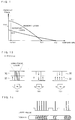
- Figure 1 shows the magnetic properties
- Figure 2 shows the overwriting process.
- the compositions of the two layers are adjusted so that the coercive force of the reference layer (Hr2) is smaller than that of the memory layer (Hr1) at room temperature (Tamb1), and the Curie temperature of the reference layer (Tc2) is higher than that of the memory layer (Tc1).
- one of the characteristics of this method is that an initialising field, as well as a bias field for recording, is applied before data is recorded on the memory layer.
- the directions of the bias field and the initialising field are anti-parallel.
- the magnitude of the bias field Hb is set at such a small value as to maintain the magnetisation of the reference layer unreversed in the L process, which will be referred to later.
- the magnitude of the initialising field Hini is set at a value larger than Hr2 but smaller than Hr1.
- Hini the magnetisation of the reference layer is oriented parallel to Hini (downward in the figure). The data recorded in the memory layer is not affected by Hini.
- the H process or L process is performed, depending on the bit data to be recorded.
- a low-power laser beam in the form of pulses is emitted so that the temperature of the memory layer TmL becomes Tc1 ⁇ TmL ⁇ Tc2.
- the magnetisation of the reference layer is not reversed. Therefore, the magnetisation of the memory layer is oriented in a direction determined by the exchange-coupling with the reference layer during the cooling process.
- exchange-coupling here means a phenomenon such that the subnetwork magnetisations of RE and TM atoms are aligned to those of similar, respectively, even in different layers.
- the magnetisation of the reference layer first coincides with the direction of the bias field (upward in the figure). That is, the direction of magnetisation of the reference layer is reversed.
- the magnetisation of the memory layer is oriented in a direction determined by the exchange-coupling with the reference layer. Since the direction of magnetisation of the reference layer has been reversed from that in the L process, the direction of magnetisation of the memory layer is also reversed from that in the L process.
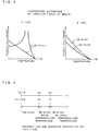
- Figure 3 shows two types of temperature dependence of the coercive force of double-layered films used in the present invention.
- a Curie temperature is a temperature at which the coercive force becomes zero.
- a compensation temperature is a temperature at which the coercive force diverges. In either case, the following two requirements must be satisfied:
- the invention largely removes restrictions on the materials used for media.
- a medium in the form of a lamination consisting of (1) an RE-rich layer without a compensation temperature and (2) a TM-rich layer is called A-type
- a medium in the form of a lamination consisting of (1) an RE-rich layer without a compensation temperature and (2) a RE-rich layer with a compensation temperature is called B-type.
- either of the two layers may be used as the memory layer.
- the layer facing the laser source behaves as the memory layer.
- an intermediate layer whose thickness does not prevent exchange-coupling between them. Insertion of a layer such as Tb or GdFeCo in order to adjust the strength of exchange-coupling is a known technique. See, for example, K. Aratani et al., "Overwriting on a magneto-optical disk with magnetic triple layers by means of the light intensity modulation method," Proc. SPIE 1078, 265 (1989).
- the magnetisation of the layer that will function as the reference layer is oriented in one direction.
- overwriting is possible in whatever state the memory layer is magnetised beforehand.
- magnetisation may be oriented in one direction beforehand throughout the entirety of the medium, including the reference layer. Therefore, preliminary magnetisation of the reference layer can be carried out by magnetising it uniformly in a sufficiently strong field before shipment. If the medium is not magnetised before shipment, magnetisation may be carried out by using a magneto-optical recording apparatus referred to later.
- bit data is written on the medium in a bias field. It is preferable to use short pulses (of a few nanoseconds) for writing one of the bit data and long pulses (tens of nanoseconds or more) for writing the other of the bit data. As disclosed by T. Ohtsuki et al.
- the direction of magnetisation of the memory layer is determined by the exchange-coupling with the reference layer. It is sufficient to apply a field of the order of 500 (Oe) by using, for example, a permanent magnet.
- the process executed while the reference layer is maintained at a low temperature below its Curie temperature is called the L process.
- both layers are heated above their Curie temperatures and marked temperature gradients are not induced in the direction of the thickness of the medium.
- magnetisation of each of the two layers is determined according to the direction of the bias field, because the exchange-coupling between the two layers is sufficiently small (if the Curie temperatures of the two layers are absolutely equal, the strength is 0 (Oe)).
- the process that includes a step in which the reference layer is heated to a high temperature near or above its Curie temperature is called the H process.
- the direction of magnetisation of the memory layer is determined by the bias field for the layer whose Curie temperature is higher (TcH layer). Therefore, at the instant when the medium has further cooled to the Curie temperature of the other layer (TcL layer), exchange-coupling with the TcH layer as well as the bias field is exerted on the TcL layer. At this time, the larger the difference between the Curie temperatures of the two layers, the greater the strength of the exchange-coupling. In the present invention, however, it is required that the direction of magnetisation of the TcL layer should follow the direction of the bias field.
- the difference between the Curie temperatures of the two layers must be so small that the strength of the exchange-coupling between the two layers does not prevent magnetisation of the memory layer by the bias field. As explained above, it is easy to produce such a double-layered film in which the Curie temperatures are sufficiently close.
- the memory layer 10 When short pulses are emitted, the memory layer 10 is heated to a temperature TmL above its Curie temperature, but the reference layer 12 is heated only to a temperature TrL below its Curie temperature (see Figure 5). As a result, immediately after the heating, only the reference layer 12 in the heated area maintains the magnetisation set before the heating (see (A) in Figure 6). When the memory layer 10 has cooled, the magnetisation is oriented downward by exchange-coupling with the reference layer 12 (see (B) in Figure 6).
- both the memory layer 10 and the reference layer 12 are heated to temperatures (TmH and TrH) above their Curie temperatures (see Figure 5). As a result, both layers in the heated area lose their magnetisations set before the heating (see (A) in Figure 7). When the medium has cooled, the magnetisation of both layers is oriented upward by the bias field ((B) in Figure 7). Throughout the L process ( Figure 6) and the H process ( Figure 7), the magnetisation of the reference layer 12 is maintained upward as in the original state.
- the memory layer 20 When short pulses are emitted, the memory layer 20 is heated to the temperature TmL above its Curie temperature, but the reference layer 22 is heated only to the temperature TrL below its Curie temperature (see Figure 8). Therefore, immediately after the heating, only the reference layer 22 maintains the magnetisation set before the heating in the heated area (see (A) in Figure 9).
- the magnetisation When the memory layer 20 is cooled below the Curie temperature, the magnetisation is first oriented downward by the exchange-coupling with the reference layer 22 (see (B) in Figure 9). When the memory layer 20 is further cooled below its compensation temperature, the magnetisation is changed upward, and the medium is stabilised in this state at room temperature.
- both the memory layer 20 and the reference layer 22 are heated to temperatures (TmH and TrH) above their Curie temperatures (see Figure 8). As a result, both layers in the heated area lose their magnetisation set before the heating (see (A) in Figure 10).
- TmH and TrH temperatures above their Curie temperatures
- both layers in the heated area lose their magnetisation set before the heating (see (A) in Figure 10).
- the magnetisation of both layers is first oriented upward by the bias field ((B) in Figure 10).
- the temperature of the memory layer 20 decreases below its compensation temperature, only the magnetisation of the memory layer 20 is reversed downward ((C) in Figure 10).
- the direction of magnetisation of the reference layer 22 remains upward as in the initial state.
- the memory layer 30 When short pulses are emitted, the memory layer 30 is heated to a temperature TmL above its Curie temperature, but the reference layer 32 is heated only to a temperature TrL below its Curie temperature (see Figure 11). If the peak temperature TrL is lower than the compensation temperature immediately after the heating, only the reference layer 32 maintains the magnetisation set before the heating in the heated area (see (A) in Figure 12). Therefore, when the memory layer 30 is cooled below its Curie temperature, the magnetisation is oriented upward by exchange-coupling with the reference layer 32 (see (B) in Figure 12). In another case where the peak temperature TrL of the reference layer 32 exceeds the compensation temperature, the direction of magnetisation of the reference layer 32 immediately after the heating is reversed downward ((A′) in Figure 12).
- both the memory layer 30 and the reference layer 32 are heated to temperatures (TmH and TrH) above their respective Curie temperatures (see Figure 11). Therefore, both layers in the heated area lose their magnetisation set before the heating (see (A) in Figure 13).
- TmH and TrH temperatures above their respective Curie temperatures
- both layers in the heated area lose their magnetisation set before the heating (see (A) in Figure 13).
- the magnetisation of both layers is first oriented downward by the bias field ((B) in Figure 13).
- the temperature of the reference layer 32 decreases below the compensation temperature, only the magnetisation of the reference layer 32 is reversed upward ((C) in Figure 13).
- the magnetisation of the reference layer 32 remains upward as in the initial state.
- Figure 14 is a schematic diagram of the laser power and the shape of the domains formed upon execution of overwriting.
- a continuous series of short pulses is used for one of the bit data, and long pulses different in duration are used for the other of the bit data.
- the formed domains are shaped like arrow feathers, in the same way as those formed by the field modulation overwrite method. Therefore, compatibility of data is expected between the light modulation overwrite method and the field modulation overwrite method.
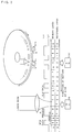
- FIG. 15 shows a schematic view illustrating the composition of a magneto-optical recording apparatus according to the invention.
- This apparatus includes a means 42, which may be a rotating means, for moving a recording medium 40, a means 44 for generating a bias field, a laser source 46, and a means responsive to the bit data to be recorded for modulating the duration and power of laser pulses. Between the laser source 46 and the recording medium 40 may be interposed a known optical system.
- the means for generating a bias field may be an electromagnet or a permanent magnet. A permanent magnet is more advantageous from the viewpoint of power consumption and heat generation.
- the means 48 modulates the time width and strength of the current pulses to be supplied to the semiconductor diode, in response to the bit data to be recorded.
- the magnetisation can be oriented in one direction throughout the medium, including the reference layer, before the bit data are recorded.
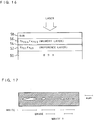
- Figure 16 shows the construction of a medium used in an experiment on overwriting.
- a RE-rich reference layer 52 that is 1200 angstroms thick and made of Tb31Fe69
- an intermediate layer 54 that is 6 angstroms thick and made of Tb
- a TM-rich memory layer 56 that is 800 angstroms thick and made of Tb20.5Fe79.5
- a protective layer 58 that is 700 angstroms thick and made of SiN.
- the thicknesses of the respective layers were estimated from their sputtering times.
- the memory layer 56 and the reference layer 52 of the prepared medium were oriented in one direction beforehand.
- the diameter of the focused laser spot used in the experiment was 0.47 microns (full-width at half-maximum), and the laser beam was emitted from the side of the protective layer 58 of the medium.
- the strength of the bias field was 480 (Oe), and the numerical aperture of the objective lens of the optical system was 0.95.
- the L process (writing) and H process (erasure) of overwriting are as shown in Figures 7 and 8, respectively.
- the duration of the laser pulse was 3.8 ns, and the power was 14.5 mW.
- the duration of the laser pulse was 50 ns, and the power was 4.5 mW.
- the power range that permits writing was examined by varying the power while maintaining the duration of the laser pulse for the writing process (L process) at 3.8 ns.
- the successful range was from 10 mW to 37 mW.
Landscapes
- Physics & Mathematics (AREA)
- Optics & Photonics (AREA)
Applications Claiming Priority (2)
| Application Number | Priority Date | Filing Date | Title |
|---|---|---|---|
| JP3021472A JP2567996B2 (ja) | 1991-01-23 | 1991-01-23 | 光磁気記録方法及び装置 |
| JP21472/91 | 1991-01-23 |
Publications (3)
| Publication Number | Publication Date |
|---|---|
| EP0496556A2 true EP0496556A2 (de) | 1992-07-29 |
| EP0496556A3 EP0496556A3 (en) | 1992-11-25 |
| EP0496556B1 EP0496556B1 (de) | 1998-04-22 |
Family
ID=12055920
Family Applications (1)
| Application Number | Title | Priority Date | Filing Date |
|---|---|---|---|
| EP92300460A Expired - Lifetime EP0496556B1 (de) | 1991-01-23 | 1992-01-20 | Magneto-optische Aufzeichnung |
Country Status (11)
| Country | Link |
|---|---|
| US (2) | US5224080A (de) |
| EP (1) | EP0496556B1 (de) |
| JP (1) | JP2567996B2 (de) |
| KR (1) | KR950010421B1 (de) |
| CN (1) | CN1023264C (de) |
| AR (1) | AR244457A1 (de) |
| BR (1) | BR9200185A (de) |
| CA (1) | CA2059179C (de) |
| DE (1) | DE69225154T2 (de) |
| MY (2) | MY119488A (de) |
| TW (1) | TW198758B (de) |
Cited By (3)
| Publication number | Priority date | Publication date | Assignee | Title |
|---|---|---|---|---|
| EP0611120A3 (de) * | 1993-02-10 | 1995-02-01 | Canon Kk | Überschreibungsfähiges magnetooptisches Aufzeichnungsverfahren. |
| EP0596716A3 (de) * | 1992-11-06 | 1996-09-11 | Sharp Kk | Magnetooptischer Aufzeichungsträger, Aufzeichnungs- und Wiedergabemethode sowie für diesen magnetooptischen Aufzeichnungsträger entworfener optischer Abtastkopf. |
| US6665235B2 (en) | 1992-11-06 | 2003-12-16 | Sharp Kabushiki Kaisha | Magneto-optical recording medium and recording and reproducing method and optical head designed for the magneto-optical recording medium |
Families Citing this family (18)
| Publication number | Priority date | Publication date | Assignee | Title |
|---|---|---|---|---|
| JP2567996B2 (ja) * | 1991-01-23 | 1996-12-25 | インターナショナル・ビジネス・マシーンズ・コーポレイション | 光磁気記録方法及び装置 |
| JPH04355239A (ja) * | 1991-05-31 | 1992-12-09 | Ricoh Co Ltd | 光磁気記録方法及び光磁気記録媒体 |
| JP3159742B2 (ja) * | 1991-10-07 | 2001-04-23 | キヤノン株式会社 | 光磁気記録再生方法 |
| JPH06131722A (ja) * | 1992-10-16 | 1994-05-13 | Canon Inc | 光磁気記録媒体およびその記録方法 |
| JP3056902B2 (ja) * | 1992-11-30 | 2000-06-26 | キヤノン株式会社 | 光磁気記録媒体 |
| JP3092363B2 (ja) | 1992-12-01 | 2000-09-25 | 松下電器産業株式会社 | 光磁気記録媒体 |
| JPH07311986A (ja) * | 1994-05-18 | 1995-11-28 | Matsushita Electric Ind Co Ltd | 光磁気記録媒体 |
| US5414678A (en) * | 1994-09-02 | 1995-05-09 | Minnesota Mining And Manufacturing Company | Magneto-optic recording medium having two recording layers, and drive for same |
| KR970010705A (ko) * | 1995-08-28 | 1997-03-27 | 안승찬 | 바이오 세라믹을 이용한 판넬 |
| US20030179657A1 (en) * | 2000-04-19 | 2003-09-25 | Hitoshi Noguchi | Magneto-optical disk device capable of performing magnetic domain expansion reproduction by dc magnetic field and reproducing method |
| CN100364097C (zh) * | 2003-03-31 | 2008-01-23 | 松下电器产业株式会社 | 存储单元、使用该存储单元的存储器、存储单元制造方法和存储器记录/读取方法 |
| EP1610387B1 (de) | 2003-03-31 | 2010-05-19 | Panasonic Corporation | Speicherzelle, speicher mit der speicherzelle, speicherzellenherstellungsverfahren und speicheraufzeichnungs-/leseverfahren |
| US7736765B2 (en) * | 2004-12-28 | 2010-06-15 | Seagate Technology Llc | Granular perpendicular magnetic recording media with dual recording layer and method of fabricating same |
| US8110298B1 (en) | 2005-03-04 | 2012-02-07 | Seagate Technology Llc | Media for high density perpendicular magnetic recording |
| US8119263B2 (en) * | 2005-09-22 | 2012-02-21 | Seagate Technology Llc | Tuning exchange coupling in magnetic recording media |
| US8697260B2 (en) * | 2008-07-25 | 2014-04-15 | Seagate Technology Llc | Method and manufacture process for exchange decoupled first magnetic layer |
| US7867637B2 (en) * | 2008-11-17 | 2011-01-11 | Seagate Technology Llc | Low coupling oxide media (LCOM) |
| US9142240B2 (en) | 2010-07-30 | 2015-09-22 | Seagate Technology Llc | Apparatus including a perpendicular magnetic recording layer having a convex magnetic anisotropy profile |
Family Cites Families (10)
| Publication number | Priority date | Publication date | Assignee | Title |
|---|---|---|---|---|
| JP2521908B2 (ja) * | 1985-06-11 | 1996-08-07 | 株式会社ニコン | オ―バ―ライト可能な光磁気記録方法、それに使用される光磁気記録装置及び光磁気記録媒体、並びに変調方法、変調装置及び光磁気記録媒体 |
| CA1322408C (en) * | 1986-08-20 | 1993-09-21 | Tomiji Tanaka | Thermomagnetic recording method applying power modulated laser on a magnetically coupled double layer structure of perpendicular anisotropy film |
| JP2642639B2 (ja) * | 1987-09-14 | 1997-08-20 | オリンパス光学工業株式会社 | 光磁気記録方法 |
| JP2712301B2 (ja) * | 1988-06-07 | 1998-02-10 | 株式会社ニコン | オーバーライト可能な光磁気記録媒体 |
| JP2712312B2 (ja) * | 1988-06-24 | 1998-02-10 | 株式会社ニコン | オーバーライト可能な光磁気記録媒体 |
| JPH0227548A (ja) * | 1988-07-15 | 1990-01-30 | Nikon Corp | 小型化されたow型光磁気記録装置 |
| EP0382859B1 (de) * | 1988-08-24 | 1998-11-04 | Mitsubishi Denki Kabushiki Kaisha | Magnetooptisches speichermedium |
| JPH03113760A (ja) * | 1989-09-22 | 1991-05-15 | Nikon Corp | 光磁気ピットポジション記録方法及びそれに使用される記録装置 |
| US5235569A (en) * | 1990-06-13 | 1993-08-10 | Nikon Corporation | Magnetooptical recording method, and apparatus used in the method |
| JP2567996B2 (ja) * | 1991-01-23 | 1996-12-25 | インターナショナル・ビジネス・マシーンズ・コーポレイション | 光磁気記録方法及び装置 |
-
1991
- 1991-01-23 JP JP3021472A patent/JP2567996B2/ja not_active Expired - Fee Related
- 1991-09-30 TW TW080107705A patent/TW198758B/zh active
- 1991-10-24 AR AR91321504A patent/AR244457A1/es active
- 1991-12-20 MY MYPI95002367A patent/MY119488A/en unknown
- 1991-12-20 CN CN91111738A patent/CN1023264C/zh not_active Expired - Fee Related
- 1991-12-20 MY MYPI91002378A patent/MY110296A/en unknown
- 1991-12-20 KR KR1019910023600A patent/KR950010421B1/ko not_active Expired - Fee Related
-
1992
- 1992-01-10 CA CA002059179A patent/CA2059179C/en not_active Expired - Fee Related
- 1992-01-20 EP EP92300460A patent/EP0496556B1/de not_active Expired - Lifetime
- 1992-01-20 DE DE69225154T patent/DE69225154T2/de not_active Expired - Fee Related
- 1992-01-22 BR BR929200185A patent/BR9200185A/pt unknown
- 1992-02-18 US US07/821,520 patent/US5224080A/en not_active Expired - Fee Related
- 1992-11-03 US US07/970,895 patent/US5325343A/en not_active Expired - Lifetime
Cited By (7)
| Publication number | Priority date | Publication date | Assignee | Title |
|---|---|---|---|---|
| EP0596716A3 (de) * | 1992-11-06 | 1996-09-11 | Sharp Kk | Magnetooptischer Aufzeichungsträger, Aufzeichnungs- und Wiedergabemethode sowie für diesen magnetooptischen Aufzeichnungsträger entworfener optischer Abtastkopf. |
| EP0974961A3 (de) * | 1992-11-06 | 2000-07-05 | Sharp Kabushiki Kaisha | Magnetooptischer Aufzeichnungsträger und Verfahren zur Aufzeichnung und Wiedergabe und für den magnetooptischen Aufzeichnungsträger ausgebildetes optische Kopf |
| US6261707B1 (en) | 1992-11-06 | 2001-07-17 | Sharp Kabushiki Kaisha | Magneto-optical recording medium and recording and reproducing method and optical head designed for the magneto-optical recording medium |
| US6483785B1 (en) | 1992-11-06 | 2002-11-19 | Sharp Kk | Magneto-optical recording method using the relation of beam diameter and an aperture of converging lens |
| US6665235B2 (en) | 1992-11-06 | 2003-12-16 | Sharp Kabushiki Kaisha | Magneto-optical recording medium and recording and reproducing method and optical head designed for the magneto-optical recording medium |
| EP0611120A3 (de) * | 1993-02-10 | 1995-02-01 | Canon Kk | Überschreibungsfähiges magnetooptisches Aufzeichnungsverfahren. |
| US5652738A (en) * | 1993-02-10 | 1997-07-29 | Canon Kabushiki Kaisha | Magnetooptical recording method for overwriting information on a recording medium includes selecting one of two recording modes based on recording information |
Also Published As
| Publication number | Publication date |
|---|---|
| CA2059179C (en) | 1996-09-17 |
| BR9200185A (pt) | 1992-10-06 |
| CN1063573A (zh) | 1992-08-12 |
| US5325343A (en) | 1994-06-28 |
| MY119488A (en) | 2005-06-30 |
| DE69225154T2 (de) | 1998-11-19 |
| DE69225154D1 (de) | 1998-05-28 |
| AR244457A1 (es) | 1993-10-29 |
| US5224080A (en) | 1993-06-29 |
| CN1023264C (zh) | 1993-12-22 |
| JPH04238132A (ja) | 1992-08-26 |
| JP2567996B2 (ja) | 1996-12-25 |
| MY110296A (en) | 1998-04-30 |
| EP0496556B1 (de) | 1998-04-22 |
| EP0496556A3 (en) | 1992-11-25 |
| KR920015293A (ko) | 1992-08-26 |
| TW198758B (de) | 1993-01-21 |
| KR950010421B1 (ko) | 1995-09-16 |
Similar Documents
| Publication | Publication Date | Title |
|---|---|---|
| EP0496556B1 (de) | Magneto-optische Aufzeichnung | |
| US5216663A (en) | Magneto-optic recording medium and manufacturing method | |
| US5087532A (en) | Direct-overwrite magneto-optic media | |
| US5163031A (en) | Method of recording tetra-value signal on magneto-optical recording medium with plural magnetic layers | |
| US5679455A (en) | Magneto-optic recording medium and apparatus | |
| US6671233B1 (en) | Magneto-optical recording medium and reproduction method therefor | |
| US5187694A (en) | Magneto-optical recording medium comprising recording layer and thermal bias layer, and method for recording, erasing and overwriting on the medium | |
| KR940001452B1 (ko) | 광자기 기록매체 및 이를 사용한 광자기 기록재생장치 | |
| US5965285A (en) | Magneto-optical recording medium and reproducing method for the same | |
| US5091896A (en) | Method and apparatus for magneto-optical recording using a demagnetization field and erasing using external magnetic field | |
| JPH0573981A (ja) | パワーマージンが拡大されたオーバーライト可能な光磁気記録方法及びそれに使用される光磁気記録装置 | |
| US5105400A (en) | Method of magneto-optically recording and erasing information onto a magneto-optical information storage medium | |
| JP2828993B2 (ja) | 光磁気記録媒体及びそれを用いた情報記録方法 | |
| US5574703A (en) | Magneto-optical method and apparatus for recording/reproducing data | |
| JP3092363B2 (ja) | 光磁気記録媒体 | |
| JP2941486B2 (ja) | 光磁気記録媒体 | |
| KR930010474B1 (ko) | 광자기 기록매체 및 광자기 기록매체의 제조방법 | |
| JP3592399B2 (ja) | 光磁気記録媒体 | |
| JP2782957B2 (ja) | 光磁気記録媒体 | |
| JP3057450B2 (ja) | 光磁気記録媒体 | |
| JP3228964B2 (ja) | 光磁気記録媒体 | |
| JPH01220239A (ja) | 光磁気記録素子 | |
| JPS63237242A (ja) | 光磁気記録方式 | |
| JPH02128342A (ja) | 光磁気記録媒体及びそれを用いた情報記録方法 | |
| JPH09282726A (ja) | 光磁気記録媒体 |
Legal Events
| Date | Code | Title | Description |
|---|---|---|---|
| PUAI | Public reference made under article 153(3) epc to a published international application that has entered the european phase |
Free format text: ORIGINAL CODE: 0009012 |
|
| AK | Designated contracting states |
Kind code of ref document: A2 Designated state(s): DE FR GB IT |
|
| PUAL | Search report despatched |
Free format text: ORIGINAL CODE: 0009013 |
|
| AK | Designated contracting states |
Kind code of ref document: A3 Designated state(s): DE FR GB IT |
|
| 17P | Request for examination filed |
Effective date: 19921119 |
|
| 17Q | First examination report despatched |
Effective date: 19950224 |
|
| GRAG | Despatch of communication of intention to grant |
Free format text: ORIGINAL CODE: EPIDOS AGRA |
|
| GRAG | Despatch of communication of intention to grant |
Free format text: ORIGINAL CODE: EPIDOS AGRA |
|
| GRAH | Despatch of communication of intention to grant a patent |
Free format text: ORIGINAL CODE: EPIDOS IGRA |
|
| GRAH | Despatch of communication of intention to grant a patent |
Free format text: ORIGINAL CODE: EPIDOS IGRA |
|
| GRAA | (expected) grant |
Free format text: ORIGINAL CODE: 0009210 |
|
| AK | Designated contracting states |
Kind code of ref document: B1 Designated state(s): DE FR GB IT |
|
| ITF | It: translation for a ep patent filed | ||
| REF | Corresponds to: |
Ref document number: 69225154 Country of ref document: DE Date of ref document: 19980528 |
|
| ET | Fr: translation filed | ||
| PLBE | No opposition filed within time limit |
Free format text: ORIGINAL CODE: 0009261 |
|
| 26N | No opposition filed | ||
| REG | Reference to a national code |
Ref country code: GB Ref legal event code: IF02 |
|
| PGFP | Annual fee paid to national office [announced via postgrant information from national office to epo] |
Ref country code: FR Payment date: 20020116 Year of fee payment: 11 |
|
| PGFP | Annual fee paid to national office [announced via postgrant information from national office to epo] |
Ref country code: DE Payment date: 20021230 Year of fee payment: 12 |
|
| PG25 | Lapsed in a contracting state [announced via postgrant information from national office to epo] |
Ref country code: FR Free format text: LAPSE BECAUSE OF NON-PAYMENT OF DUE FEES Effective date: 20030930 |
|
| REG | Reference to a national code |
Ref country code: FR Ref legal event code: ST |
|
| PGFP | Annual fee paid to national office [announced via postgrant information from national office to epo] |
Ref country code: GB Payment date: 20040105 Year of fee payment: 13 |
|
| PG25 | Lapsed in a contracting state [announced via postgrant information from national office to epo] |
Ref country code: DE Free format text: LAPSE BECAUSE OF NON-PAYMENT OF DUE FEES Effective date: 20040803 |
|
| PG25 | Lapsed in a contracting state [announced via postgrant information from national office to epo] |
Ref country code: IT Free format text: LAPSE BECAUSE OF NON-PAYMENT OF DUE FEES;WARNING: LAPSES OF ITALIAN PATENTS WITH EFFECTIVE DATE BEFORE 2007 MAY HAVE OCCURRED AT ANY TIME BEFORE 2007. THE CORRECT EFFECTIVE DATE MAY BE DIFFERENT FROM THE ONE RECORDED. Effective date: 20050120 Ref country code: GB Free format text: LAPSE BECAUSE OF NON-PAYMENT OF DUE FEES Effective date: 20050120 |
|
| GBPC | Gb: european patent ceased through non-payment of renewal fee |
Effective date: 20050120 |