EP0496560A2 - Verfahren und Vorrichtung zum Walzformen von Streifenmaterial - Google Patents
Verfahren und Vorrichtung zum Walzformen von Streifenmaterial Download PDFInfo
- Publication number
- EP0496560A2 EP0496560A2 EP92300469A EP92300469A EP0496560A2 EP 0496560 A2 EP0496560 A2 EP 0496560A2 EP 92300469 A EP92300469 A EP 92300469A EP 92300469 A EP92300469 A EP 92300469A EP 0496560 A2 EP0496560 A2 EP 0496560A2
- Authority
- EP
- European Patent Office
- Prior art keywords
- unit
- strip
- roll
- strip material
- rolls
- Prior art date
- Legal status (The legal status is an assumption and is not a legal conclusion. Google has not performed a legal analysis and makes no representation as to the accuracy of the status listed.)
- Granted
Links
Images


Classifications
-
- B—PERFORMING OPERATIONS; TRANSPORTING
- B26—HAND CUTTING TOOLS; CUTTING; SEVERING
- B26D—CUTTING; DETAILS COMMON TO MACHINES FOR PERFORATING, PUNCHING, CUTTING-OUT, STAMPING-OUT OR SEVERING
- B26D7/00—Details of apparatus for cutting, cutting-out, stamping-out, punching, perforating, or severing by means other than cutting
- B26D7/26—Means for mounting or adjusting the cutting member; Means for adjusting the stroke of the cutting member
- B26D7/2628—Means for adjusting the position of the cutting member
- B26D7/265—Journals, bearings or supports for positioning rollers or cylinders relatively to each other
-
- B—PERFORMING OPERATIONS; TRANSPORTING
- B21—MECHANICAL METAL-WORKING WITHOUT ESSENTIALLY REMOVING MATERIAL; PUNCHING METAL
- B21D—WORKING OR PROCESSING OF SHEET METAL OR METAL TUBES, RODS OR PROFILES WITHOUT ESSENTIALLY REMOVING MATERIAL; PUNCHING METAL
- B21D5/00—Bending sheet metal along straight lines, e.g. to form simple curves
- B21D5/06—Bending sheet metal along straight lines, e.g. to form simple curves by drawing procedure making use of dies or forming-rollers, e.g. making profiles
- B21D5/08—Bending sheet metal along straight lines, e.g. to form simple curves by drawing procedure making use of dies or forming-rollers, e.g. making profiles making use of forming-rollers
-
- B—PERFORMING OPERATIONS; TRANSPORTING
- B26—HAND CUTTING TOOLS; CUTTING; SEVERING
- B26D—CUTTING; DETAILS COMMON TO MACHINES FOR PERFORATING, PUNCHING, CUTTING-OUT, STAMPING-OUT OR SEVERING
- B26D7/00—Details of apparatus for cutting, cutting-out, stamping-out, punching, perforating, or severing by means other than cutting
- B26D7/26—Means for mounting or adjusting the cutting member; Means for adjusting the stroke of the cutting member
- B26D7/2614—Means for mounting the cutting member
Definitions
- the invention relates to a method and apparatus for a roll forming strip material.
- Roll forming is used extensively for shaping strip metal material, particularly aluminium alloy material, which is used in a large variety of ways.
- Strip material is used for venetian blinds slats and for panelling materials and often it is necessary to effect quite marked deformations of the strip material during the roll forming process.
- the roll forming apparatus must be capable of being changed over from making one product to making another. For example, it is quite common for the strip material to be available in a number of different finishes and a number of different widths and when one particular production run has been completed, it is necessary to change over to another stock of strip material or to adapt the forming rolls for other shapes of product and in order to vary the length of the finished products to be cut off.
- It is now proposed, according to one aspect of the present invention, to provide a method of roll forming strip material comprising continuously feeding the strip material from a coil thereof by means of a strip feed unit, cutting off a predetermined length thereof as the strip is fed and continuing to feed the cut length of strip material through at least one roll form unit, the drive of the rolls of which is arranged to feed the strip material at least as fast as the rate at which the strip feed unit feeds the material.
- the at least one roll form unit comprises one of a set of such units and, when it is desired to change the profile of a rolled strip material, the roll form unit is disconnected from the strip feed unit and it is replaced by a different one of the set. It has been found that this can be carried out very rapidly, particularly as the rolls of the roll form unit themselves do not have to be changed, but merely the whole unit has to be changed.
- the length of the strip material fed into the strip unit is sensed by means of a strip length recording unit, and a signal from the recording unit is used to trigger the cutting off of the strip material.
- This cutting is advantageously carried out by a rotary cutter mounted on the strip feed unit and the signal from the recording unit triggers a clutch to operate the rotary cutting unit.
- the strip material should be punched, to provide apertures, notches, tabs etc., in the finally rolled strip material. It is contemplated that this could be effected by interposing between the strip feed unit and said at least one roll form unit, a punching unit which is advantageously designed to punch the cut strip material as it is fed therethrough, without interrupting the supply of the cut strip material to the roll form unit.
- a strip forming apparatus comprising a support for at least one coil of strip material, a strip feed unit including feed rollsfor feeding strip material from a coil thereof mounted on said support, a cutter on said strip feed unit for cutting off a predetermined length of strip material as the strip material is fed, at least one roll form unit mounted adjacent said strip feed unit to receive cut strip material lengths therefrom, forming rolls mounted in said at least one roll form unit, and means to drive the feed rolls of the strip feed unit and the forming rolls of said at least one roll form unit, whereby the peripheral speed of the rolls of the roll form unit is at least the same as the peripheral speed of the rolls of the strip feed unit.
- the drive means is mounted on the feed unit and causes the rolls of the at least one roll forming unit to be driven at the same peripheral speed as that of the rolls of the strip feed unit.
- the feed unit which includes a drive pinion, driven by said drive means, said drive pinion being engageable with a driven pinion mounted on the roll forming unit, with the pitch circles of the pinions have a common tangent lying on the abutting end faces of the feed unit and the roll forming unit respectively.
- the drive means may include a motor driving a flexible drive element, e.g. a double-sided toothed belt, which passes around wheels,e.g. toothed wheels, mounted to rotate with the feed rolls and the drive roll.
- a flexible drive element e.g. a double-sided toothed belt, which passes around wheels,e.g. toothed wheels, mounted to rotate with the feed rolls and the drive roll.
- the cutter may be a rotary cutter assembly and, if desired, this may be driven by the flexible drive element and thus may itself include a further wheel, e.g. a toothed wheel.
- the feed unit may further comprise a strip length recording unit which gives a signal when a predetermined length of strip material has been fed into the feed unit.
- a clutch may be associated with the cutter, the clutch being operable by a signal.
- a rotary cutter it may comprise a first roll with a blade on its periphery, a second roll with a complementary groove on its periphery, means mounting said rolls for counter-rotation, one of said rolls being eccentrically mounted so that, in one rotational position, strip material can pass freely between the first and second rolls and, upon rotation from that position, the blade is brought into contact with the strip material to cut it.
- the feed unit may be provided with means signalling an obstruction of the strip feed and disengaging the drive in case of malfunction.
- the support for the coil of strip material advantageously comprises a generally horizontal support surface on which the strip coil is mounted, with its axis vertical, this has the advantage that the strip can uncoil in an orderly manner, because gravity urges it towards the supporting surface. Furthermore, the coils of strip material are held in position on the coil holder by gravity without requiring any further positioning means.
- a guide means is provided to change the orientation of the strip material so that it lies in a horizontal plane as it is fed into the feed unit.
- a plurality of horizontal supports may be provided, to support a plurality of coils from which a selected strip may be fed.
- roll forming strip material may be of different widths, from time to time one needs to provide rolls which are of a different axial length in the same roll forming unit, rather than supply a different roll forming unit. Conventionally this is done by having each roll formed by two end portions and a centre portion. Removing or replacing the centre roll portion can be time consuming.
- a roll form unit comprising at least one pair of co-operable rolls, wherein at least one of the rolls of said at least one roll form unit comprises a shaft having an axial key thereon, two end roll portions each having a keyway co-operable with said key, means to releasably lock said end roll portions onto said shaft to allow said portions to be moved axially, at least two pairs of semi-cylindrical centre shell portions mounted on said shaft between said end roll portions, the shell portions of one pair each having a semi-circular ridge at one axial end and the shell portions of the other pair having a semi-circular cavity at the end facing the shells of said one pair, and keyways in said shell portions offset by 90°, whereby when said pairs of shell portions are clamped between said end roll portions, the rims engage in the grooves to lock said shell portions in place.
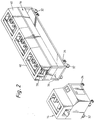
- the apparatus illustrated includes several basic assemblies. Thus there is a support assembly 10 followed by a guide assembly 12, a working assembly 13 and an out-feed table 18.
- the working assembly 13 includes a cutting and in-feed unit 14 and a roll forming unit 16. This may be one of several roll forming units and a second unit 17 may be used to replace the unit 16.
- the support assembly illustrated comprises a base 20, having an upstanding pillar 22 on which are pivotally mounted four support tables 24,25,26,27. On at least one of these is mounted a coil 28.
- the coil 28 which is being used is that on the top table 24 and the strip material 30 is fed from this via the guide assembly 12 so that the orientation of the strip material is changed from the vertical plane to the horizontal plane as the material is fed into the feed unit 14.
- Each of units 14,16 have trolley wheels 32 (see Figure 2) and retractable support legs 34 which are used when the unit has been rolled on the wheels 32 to its desired position.
- the roll forming unit 16 includes a main frame 36, a form roll assembly 38 and covers 40.
- the cutting and feed unit 14 is provided with a drive motor 42 having a drive pulley 44 thereon around which is passed a flexible drive element 46, for example, a drive chain or a double-sided toothed flexible belt.
- a flexible drive element 46 for example, a drive chain or a double-sided toothed flexible belt.
- the drive element 46 takes drive to the shaft 48 of the in-feed unit, to a disengageable clutch device 50 and to a drive pinion 52.
- the end face 54 of the unit 14 is located so as to be a tangent to the pitch circle of the pinion 52 for a reason to be explained below.
- connectors 56 which are used to cooperate with further connector elements on the roll forming unit 16.
- the pinion 52 meshes with a driven pinion 58 on the roll form unit 16, the abutting end face of which is a tangent to the pitch circle of the pinion 58 so that the two pinions 52,58 accurately mesh with one another.
- a pulley 60 or the like around which passes a further flexible drive element 62 which again may be a chain, a drive belt or in particular a double-sided toothed drive belt. This is used to drive the roller shaft 43 of the roll form unit 16.
- the drive from the single drive motor 42 is used to drive the rolls of the cutting and feed unit 14 and of the roll form unit 16.
- the rolls are driven at the same peripheral speed. It will also be possible for the rolls of the roll forming unit 16 to be driven at a higher peripheral speed than those of the unit 14.
- the actual drive arrangement for the unit 16 is fairly standard and further description of that is not thought necessary.
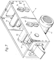
- FIG. 7 further details of the feed and cutting unit 14 are given. Many of the parts have been omitted for the sake of clarity. Lower and upper in-feed rolls 64,66 are provided, the upper one of these being mounted for limited vertical movement and being mounted on the drive shaft 48 previously described.
- a length recording unit 67 of a commercially available the supplies appropriate signals to an electronic control device, also of a commercially available type, which triggers the operation, after a predetermined interval, of the clutch device 50 (not shown in Figure 7) through which the shafts 68,70 can be driven to rotate the cutter wheels or rollers 72,74 through a full turn.
- the structure of the cutter wheels is illustrated in Figures 8 and 9.
- the drive motor 42 is shown with its toothed wheel 44 which drives a belt which in turn drives a driven wheel 45 associated with the clutch 50.
- the driven wheel 45 can thus either free wheel or the clutch can engage the shaft 76 and the gear wheel 78.
- the gear wheel 78 would drive the gear wheel 80 which, in turn, will rotate the upper shaft 82, so that the upper and lower shafts 76,82 always rotate together.
- Figures 9A and 9B show the cutter rollers 72,74 in their operative and inoperative positions. At least one of the rollers, in this case the lower roller 72, is mounted eccentrically on its shaft 76, so that upon rotation it moves towards the other roller if rotated from the inoperative position of Figure 9B to the opposite position of Figure 9A. It can be seen that the lower roller 72 is provided with a generally axially extending cavity 84 and the upper roller 74 with a complementary generally axially extending knife-blade 86. It will be appreciated that these could be mounted the other way round.
- the cutter rollers Upon actuation of the clutch 50, the cutter rollers will always rotate through a full turn in the direction of the arrows 88,90 whereupon they will again stop rotating when in a position as illustrated in Figure 9B.
- the strip material will pass from right to left, as viewed in these figures, and will be cut by the blade 86.
- a similar arrangement, not shown, can be provided in a punching unit which has not been illustrated and in which one or more holes, notches, recesses, tabs or the like may be formed in the strip material.
- a punching unit could be placed between the in-feed and cutter unit 14 and the roll forming unit 16 so that it punches unrolled material.
- the actual form of the roll assembly 38 illustrated in Figures 10, 11 and 12 includes a machine frame having a base 92, side walls 94 and a cross-brace member 96.
- Figure 10 also shows the roller shafts 43 which are each driven through a toothed wheel 98.
- the roll shafts are mounted in bearings 100, one of which, here the upper one, being adjustable to take into account the distance between the opposing shafts of a pair.
- Figure 12 illustrates in more detail the bearing arrangement for the shafts and shows how the shafts are specifically adapted to allow instant accurate relocation of the shafts with respect to the form roller frame upon each removal.
- removal of the roller shafts is necessary to arrange the form rollers thereon or any fresh form rollers when that is desired.
- the usual form of such roller 102 is illustrated in Figure 13 and is seen to comprise several separate parts 104,106,108. This arrangement allows different widths of profile to be formed with the same set of roller parts. If a middle roller part 106 is removed between the rim forming roller part 104,108, then a panel can be obtained with a narrower web profile. It will be appreciated that re-engaging of the roller parts to give the different width requires the shafts 43 to be removed.
- Figure 14 shows an alternative arrangement.
- the parts 104,108 are as in Figure 13 from which it will be seen that the central portion is made up of three units 110,112,114 each formed in two parts 110a,110b; 112a,112b; 114a,114b respectively, each of semi-annular form.
- the parts 110a,110b as well as the parts 114a,114b are each formed with semi-annular grooves 116.
- the central parts 112a,112b are formed with complementary semi-annular ridges 118 on each axial end.
- the parts 110,114 are also provided with a complementary half-keyways which are aligned with the keyway 122 of the central part 112. It will be seen that the keyway 122 is angularly displaced from the complementary half-keyways 120.
Landscapes
- Engineering & Computer Science (AREA)
- Mechanical Engineering (AREA)
- Life Sciences & Earth Sciences (AREA)
- Forests & Forestry (AREA)
- Advancing Webs (AREA)
- Perforating, Stamping-Out Or Severing By Means Other Than Cutting (AREA)
Applications Claiming Priority (2)
| Application Number | Priority Date | Filing Date | Title |
|---|---|---|---|
| GB9101289A GB2251819A (en) | 1991-01-21 | 1991-01-21 | Method and apparatus for roll forming strip material. |
| GB9101289 | 1991-01-21 |
Publications (3)
| Publication Number | Publication Date |
|---|---|
| EP0496560A2 true EP0496560A2 (de) | 1992-07-29 |
| EP0496560A3 EP0496560A3 (en) | 1992-09-09 |
| EP0496560B1 EP0496560B1 (de) | 1995-09-20 |
Family
ID=10688764
Family Applications (1)
| Application Number | Title | Priority Date | Filing Date |
|---|---|---|---|
| EP92300469A Expired - Lifetime EP0496560B1 (de) | 1991-01-21 | 1992-01-20 | Verfahren und Vorrichtung zum Walzformen von Streifenmaterial |
Country Status (3)
| Country | Link |
|---|---|
| EP (1) | EP0496560B1 (de) |
| DE (1) | DE69204858T2 (de) |
| GB (1) | GB2251819A (de) |
Cited By (2)
| Publication number | Priority date | Publication date | Assignee | Title |
|---|---|---|---|---|
| AT407496B (de) * | 1994-06-03 | 2001-03-26 | Rolf Dipl Ing Dr Techn Marr | Feststoffmasse zur, vorzugsweise im wesentlichen simultanen, entfernung von gasförmig metallischem quecksilber und ionischen quecksilberverbindungen aus prozess- und abgasströmen, verfahren zu ihrer herstellung, verfahren zu ihrer angegebenen anwendung sowie vorrichtungen zum thermischen behandeln von quecksilberkontaminierten gütern |
| CN102514027A (zh) * | 2012-01-16 | 2012-06-27 | 林志宪 | 一种用于纸张覆膜机中的切纸拉断装置 |
Family Cites Families (10)
| Publication number | Priority date | Publication date | Assignee | Title |
|---|---|---|---|---|
| GB884189A (en) * | 1959-07-09 | 1961-12-06 | Tube Making Machines Ltd | Improvements in machines for making metal tubing |
| US3413437A (en) * | 1965-04-15 | 1968-11-26 | Nippon Kokan Kk | Apparatus for the continuous manufacture of lightweight and composite metallic i-beams |
| US3421353A (en) * | 1967-10-12 | 1969-01-14 | Robertson Co H H | Method and apparatus for making corrugated building sheets |
| GB1353813A (en) * | 1971-07-07 | 1974-05-22 | Oliver Machinery Co | Roll-forming machines |
| US4549422A (en) * | 1983-04-29 | 1985-10-29 | Harrow Donald A | Cup and roll machine |
| BR8402675A (pt) * | 1984-05-30 | 1986-01-07 | Bruno Fuchs | Maquina de perfilar telhas auto-portantes |
| US4660399A (en) * | 1985-06-03 | 1987-04-28 | Suter Frank L | Mobile roll-forming machine |
| SE462202B (sv) * | 1986-08-15 | 1990-05-21 | Br Hoeglunds Maskinuthyrning A | Anlaeggning foer profilering av plaat |
| US4811587A (en) * | 1987-10-28 | 1989-03-14 | Knudson Gary Art | Apparatus for making panels |
| US4831857A (en) * | 1988-03-18 | 1989-05-23 | Tishken Products Co. | Machine with quick disconnect between spindle drive train and power transmission |
-
1991
- 1991-01-21 GB GB9101289A patent/GB2251819A/en not_active Withdrawn
-
1992
- 1992-01-20 DE DE69204858T patent/DE69204858T2/de not_active Expired - Fee Related
- 1992-01-20 EP EP92300469A patent/EP0496560B1/de not_active Expired - Lifetime
Cited By (3)
| Publication number | Priority date | Publication date | Assignee | Title |
|---|---|---|---|---|
| AT407496B (de) * | 1994-06-03 | 2001-03-26 | Rolf Dipl Ing Dr Techn Marr | Feststoffmasse zur, vorzugsweise im wesentlichen simultanen, entfernung von gasförmig metallischem quecksilber und ionischen quecksilberverbindungen aus prozess- und abgasströmen, verfahren zu ihrer herstellung, verfahren zu ihrer angegebenen anwendung sowie vorrichtungen zum thermischen behandeln von quecksilberkontaminierten gütern |
| CN102514027A (zh) * | 2012-01-16 | 2012-06-27 | 林志宪 | 一种用于纸张覆膜机中的切纸拉断装置 |
| CN102514027B (zh) * | 2012-01-16 | 2015-02-18 | 林志宪 | 一种用于纸张覆膜机中的切纸拉断装置 |
Also Published As
| Publication number | Publication date |
|---|---|
| EP0496560A3 (en) | 1992-09-09 |
| EP0496560B1 (de) | 1995-09-20 |
| GB2251819A (en) | 1992-07-22 |
| GB9101289D0 (en) | 1991-03-06 |
| DE69204858D1 (de) | 1995-10-26 |
| DE69204858T2 (de) | 1996-02-08 |
Similar Documents
| Publication | Publication Date | Title |
|---|---|---|
| DE69515784T2 (de) | Rotierendes Schneidwerkzeug | |
| US4295842A (en) | Stripping device for removing waste sheet board | |
| US6085626A (en) | Rapid adjustment rotary dies | |
| WO1999055484A9 (en) | Die-cutter with planetary configuration | |
| CN112916571B (zh) | 一种刷条回收设备 | |
| EP0496560B1 (de) | Verfahren und Vorrichtung zum Walzformen von Streifenmaterial | |
| US5657677A (en) | Apparatus having an interchangeable covering for cutting semi-rigid sheets one by one, in particular sheets of cardboard | |
| US4536176A (en) | Crimp blade holder | |
| US4089090A (en) | Arrangement for perforating a stripe | |
| JP2511784B2 (ja) | ロ―タリ―カッタ― | |
| US3192810A (en) | Punching mechanism with tool smoothing means | |
| CA2439613C (en) | Rotary apparatus and method | |
| EP0239398B1 (de) | Schneidmaschine für Zierketten | |
| EP0259433B1 (de) | Verbesserungen für querschlitzvorrichtungen | |
| DE3235690A1 (de) | Geraet zum handhaben von duennen blaettern oder materialboegen | |
| GB2406069A (en) | Methods and apparatus for die cutting | |
| US5088309A (en) | Rotary punch | |
| WO1990002639A1 (en) | Apparatus for handling sheet material | |
| US4766707A (en) | Strip of loosely connected hold down clips | |
| US2085863A (en) | Punching machine | |
| US3322011A (en) | Flying punch | |
| US4601693A (en) | Apparatus for crimping a moving web | |
| US3135152A (en) | Rotary perforating roll units supported for movement towards and away from each other | |
| US5293799A (en) | Punching and perforating unit with combined punching and perforating cylinders | |
| EP0352616B1 (de) | Kontinuierlich angetriebener Perforierer |
Legal Events
| Date | Code | Title | Description |
|---|---|---|---|
| PUAI | Public reference made under article 153(3) epc to a published international application that has entered the european phase |
Free format text: ORIGINAL CODE: 0009012 |
|
| PUAL | Search report despatched |
Free format text: ORIGINAL CODE: 0009013 |
|
| AK | Designated contracting states |
Kind code of ref document: A2 Designated state(s): DE FR GB IT NL SE |
|
| AK | Designated contracting states |
Kind code of ref document: A3 Designated state(s): DE FR GB IT NL SE |
|
| 17P | Request for examination filed |
Effective date: 19930216 |
|
| 17Q | First examination report despatched |
Effective date: 19930928 |
|
| GRAA | (expected) grant |
Free format text: ORIGINAL CODE: 0009210 |
|
| AK | Designated contracting states |
Kind code of ref document: B1 Designated state(s): DE FR GB IT NL SE |
|
| REF | Corresponds to: |
Ref document number: 69204858 Country of ref document: DE Date of ref document: 19951026 |
|
| ET | Fr: translation filed | ||
| ITF | It: translation for a ep patent filed | ||
| PLBE | No opposition filed within time limit |
Free format text: ORIGINAL CODE: 0009261 |
|
| 26N | No opposition filed | ||
| PGFP | Annual fee paid to national office [announced via postgrant information from national office to epo] |
Ref country code: SE Payment date: 19990107 Year of fee payment: 8 |
|
| PGFP | Annual fee paid to national office [announced via postgrant information from national office to epo] |
Ref country code: GB Payment date: 19990121 Year of fee payment: 8 |
|
| PGFP | Annual fee paid to national office [announced via postgrant information from national office to epo] |
Ref country code: DE Payment date: 19991231 Year of fee payment: 9 |
|
| PGFP | Annual fee paid to national office [announced via postgrant information from national office to epo] |
Ref country code: FR Payment date: 20000112 Year of fee payment: 9 |
|
| PG25 | Lapsed in a contracting state [announced via postgrant information from national office to epo] |
Ref country code: GB Free format text: LAPSE BECAUSE OF NON-PAYMENT OF DUE FEES Effective date: 20000120 |
|
| PG25 | Lapsed in a contracting state [announced via postgrant information from national office to epo] |
Ref country code: SE Free format text: LAPSE BECAUSE OF NON-PAYMENT OF DUE FEES Effective date: 20000121 |
|
| PGFP | Annual fee paid to national office [announced via postgrant information from national office to epo] |
Ref country code: NL Payment date: 20000131 Year of fee payment: 9 |
|
| GBPC | Gb: european patent ceased through non-payment of renewal fee |
Effective date: 20000120 |
|
| EUG | Se: european patent has lapsed |
Ref document number: 92300469.1 |
|
| PG25 | Lapsed in a contracting state [announced via postgrant information from national office to epo] |
Ref country code: NL Free format text: LAPSE BECAUSE OF NON-PAYMENT OF DUE FEES Effective date: 20010801 |
|
| PG25 | Lapsed in a contracting state [announced via postgrant information from national office to epo] |
Ref country code: FR Free format text: LAPSE BECAUSE OF NON-PAYMENT OF DUE FEES Effective date: 20010928 |
|
| NLV4 | Nl: lapsed or anulled due to non-payment of the annual fee |
Effective date: 20010801 |
|
| PG25 | Lapsed in a contracting state [announced via postgrant information from national office to epo] |
Ref country code: DE Free format text: LAPSE BECAUSE OF NON-PAYMENT OF DUE FEES Effective date: 20011101 |
|
| REG | Reference to a national code |
Ref country code: FR Ref legal event code: ST |
|
| PG25 | Lapsed in a contracting state [announced via postgrant information from national office to epo] |
Ref country code: IT Free format text: LAPSE BECAUSE OF NON-PAYMENT OF DUE FEES;WARNING: LAPSES OF ITALIAN PATENTS WITH EFFECTIVE DATE BEFORE 2007 MAY HAVE OCCURRED AT ANY TIME BEFORE 2007. THE CORRECT EFFECTIVE DATE MAY BE DIFFERENT FROM THE ONE RECORDED. Effective date: 20050120 |