EP0496570A2 - Dispositif d'identification d'un système à deux niveaux avec optimisation - Google Patents
Dispositif d'identification d'un système à deux niveaux avec optimisation Download PDFInfo
- Publication number
- EP0496570A2 EP0496570A2 EP92300491A EP92300491A EP0496570A2 EP 0496570 A2 EP0496570 A2 EP 0496570A2 EP 92300491 A EP92300491 A EP 92300491A EP 92300491 A EP92300491 A EP 92300491A EP 0496570 A2 EP0496570 A2 EP 0496570A2
- Authority
- EP
- European Patent Office
- Prior art keywords
- function
- parameter
- output
- values
- inputs
- Prior art date
- Legal status (The legal status is an assumption and is not a legal conclusion. Google has not performed a legal analysis and makes no representation as to the accuracy of the status listed.)
- Granted
Links
Images




Classifications
-
- G—PHYSICS
- G05—CONTROLLING; REGULATING
- G05B—CONTROL OR REGULATING SYSTEMS IN GENERAL; FUNCTIONAL ELEMENTS OF SUCH SYSTEMS; MONITORING OR TESTING ARRANGEMENTS FOR SUCH SYSTEMS OR ELEMENTS
- G05B17/00—Systems involving the use of models or simulators of said systems
- G05B17/02—Systems involving the use of models or simulators of said systems electric
Definitions
- This invention relates to a field of system control, and more particularly, to structural identification and parameter identification, and the use thereof in system controllers.
- model structure and parameters for an unknown or incompletely known process system is important for both control and diagnosis.
- Estimates of system parameters are an essential aspect of adaptive/predictive control and auto-tuning.
- changes in system parameters or structures can be valuable diagnostic indicators. For example, a sudden increase in the delay of a transport process can imply a rerouted pipeline.
- the model of the system is based on the relationship between the inputs to the systems and the outputs, or responses, identified within or from the system by sensors or other monitors of the system's activities. For example, turning up the boiler in the furnace room would increase the heat in the room at different rates depending on various other conditions within the monitored environment of the room.
- the response measured as a change in temperature in the room plotted against time, will generate some kind of curve.
- the shape of the curve, the slope of the upward response, and the order of the equation which defines the curve can each vary considerably depending on the nature of the monitored environment.
- Neural networks have their own drawbacks. They are generally time consuming and computationally expensive, particularly in the training phase, and particularly if the neural network model is implemented in software on a single processor and does not have a dedicated hardware implementation. However, as neural network processing becomes less expensive, it may be useful to use the neural network for the parameter identification as well as the structure identification.
- the two-level system identifier of this patent employs a neural network as a pattern classifier to solve the structural identification problem. It uses modern algorithmic techniques to estimate the parameter values corresponding to the identified structure.
- Initial parameter values may also be determined using a neural network.
- Continued parameter optimization of an on-line system is also taught. Finally, a description of continued on-line tuning or training, using optimization data, is described.
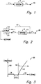
- Fig. 1 is a conceptual block diagram of a basic open-loop control system.
- Fig. 2 is a block diagram of a basic closed-loop control system.
- Fig. 3 is a plot of a response curve against time.
- Fig. 4 is a block diagram of the basic elements of the two-level system identifier.
- Fig. 5 is a more detailed block diagram of a two-level system identifier.
- Fig. 6 is a block diagram of a series of switches and structured blocks/components of a system.
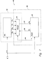
- Fig. 7 is a block diagram of a structure identifier and a parameter estimator.
- Fig. 8 is a block diagram of a controlled system.
- Fig. 9 is a block diagram of system simulation.
- Fig. 10 is a block diagram of neural network training.
- An HVAC system Heating, Ventilating and Air Conditioning system
- An HVAC system is applicable to a generally closed building space and responds to a human operator who controls the setpoints, or maybe just the temperature and windows for ventilation (and possibly curtains for modification of heat loads from sunlight and prevention of heat loss through the windows).
- the human turns the system off and uses his window controls during seasonable temperatures, keeping the air conditioning on and the curtains closed at the hottest times, and the heat on and the curtains closed at the coldest times. He generally will move the setpoint up when he feels cold and the setpoint down when he feels hot.
- the setpoint as determined on the thermostat which is in the room that the human controls, either provides input directly to the boiler, ventilating system and air conditioning, or goes through an intermediary, a controller, which will provide the same inputs to the mechanical equipment, but in a more efficient manner than the human could do so.
- a controller which will provide the same inputs to the mechanical equipment, but in a more efficient manner than the human could do so.
- a system 11 having inputs "u” and “N” going into the system, and outputs "y” coming out of the system.
- the "u” going into the system would be the heat delivered by the furnace, the coolness delivered by the air conditioner, and the rate of flow at which the ventilation (or other delivery) system delivers either of these inputs.
- the output from the room, "y”, is (in the example) the measured temperature which changes because of the inputs "u”. In the room there are uncontrolled inputs, or inputs that are controllable through means other than that available through the thermostat.
- N for "noise”
- the system 10 is identified in a qualitative manner.
- the human may effect inputs “N” without going through the controller, and inputs “u” through the controller and, if present, will do so in response to changes in the system which affect him.
- the thermostat also monitors "y” and can effect its own changes to "u” to cause “y” to match the setpoint.
- a closed-loop system 20 is described, having a system 11, noise inputs "N”, controllable inputs u, controlled outputs y, and a return loop 13 which returns y to the controller 12.
- the controller may or may not contain a model 31.
- a graph 30 of the response curve 17 plotting the response 19 (of y) against the time 18, is shown.
- dead time the time from which the signal is given to the boiler to the time at which the temperature of the room is affected.
- the droop in curve 17 indicated in the time region 15 indicates an inverse response in the response curve. This may happen where a blower goes on and cools the room somewhat before heat is delivered, for example.
- the remaining part of the curve 17 is an upward sloping curve in time area 16. This part of the curve is called the "integral action" of the response curve.
- a response curve such as this curve 17 may be produced by a single step change in setpoint in a system. Not every response curve will have the same features as this one, of course, and the response curve of room-measurable features such as humidity, rate of air flow through the room, etc., may be quite different in response to the same set of inputs into the room. For example, the slope of part 16 of curve 17 may flatten dramatically on a very hot day, if a relatively low power air cooling system is employed, or may remain quite similar, if the air cooling system is quite strong.
- the model can exhibit variations in two ways. First, structural variations are possible. Possible structural variations can include:
- the mathematical model can contain parameters which can be assigned different values. For example, when a system contains a delay, the actual value of the delay can be a parameter.
- a simulation model 61 is shown.
- the model can be a set of algorithms, programs, or even an analog device, if desired.
- a neural network 62 has associated with it a learning algorithm 63 as described previously.
- the arrows 64 represent the algorithm's ability to adjust the neural network, whether by adjusting internal weights or by other means.
- Inputs y and u pasing through the network 62 produce an output s 0, which is compared with s at point 65.
- the learning algorithm uses the comparison received on line 66 to accomplish modification through representative arrow 64. The process is iteratively repeated until s 0....x is sufficiently close to s so as to be negligible in context or minimized.
- model descriptions can be randomly or thoughtfully generated, and input parameters applied to them in simulation to generate response curves for each model.
- the neural network must be one which is capable of non-linear function mapping. Two examples would be networks that are of the back-propagation or radial-basis function types.
- the input parameters themselves may be random or carefully generated to match expected actual parameters if desired. It is probably helpful that some noise, either random or periodic, or some combination, be introduced into the simulation for robustness. Closed-loop, nonstep input, and even arbitrary inputs can be used, as well as a basic open-loop step input model.
- the more variety of models in the simulator used to create the training data set the more likely the system identifier is to select an accurate model for the system intended to be controlled in the real world. Of course, the more complexity introduced, the more costly the running of the network and the simulations is. Therefore, where the process can be accurately described as open-loop, step input, such a basis for training should be used.
- the training set of data should be compiled with a simulator which has been constructed with reference to the real world situation that the controller having the two-level system identifier will find itself employed in.
- Real world examples could be used instead, of course, but the compilation of such data would be tedious, prone to error, costly, and quite time consuming.
- the training of the neural network requires that corresponding inputs and output(s) are fed into the network, iteratively, until the output from the neural network matches the output(s) which correspond to those inputs from the given example.
- This technique and concept or tool is employed in this invention as well. It is, however, put to different purposes.
- process input and output data 21 is input to a response pattern classifier 22 and a parameter estimator 25.
- the response pattern classifier 22 provides the structure identification for the system under consideration.
- a transfer function representative of the structure identified 24 is input from the response pattern classifier 22 to the parameter estimator 25.
- the parameter estimator uses the model identified in the transfer function 24 to find initial values of the parameters 27 associated with said transfer function, and iteratively process these parameters through its internal processes until the actual process input and output data 21 match the process input and output data which would be predicted using the parameters estimated in the identified structure.
- the transfer function in which the structure 24 is identified to the parameter estimator 25, can be viewed as a series of structural switches in one embodiment.
- the inputs U(s) may be applied directly to the gain factor 35, to yield the output Y(s).
- U(s) and Y(s) are the Laplace transforms of the time-varying input and output signals, u(t) and y(t), respectively.
- Gain is generally represented as K p .
- the inputs U(s) will instead be applied through switch 31 to the delay function in box S D . If there is no delay, switch 31 will direct inputs U(s) around the delay function where they will be directed by switch 32, either around or through the lead-lag parameter function indicated by box S LL . The process is repeated for switch 33 and box S L , and switch 34 and box S I , the lag and integral functions respectively. Thus, if all the switches go through the function boxes, the system is identified as having a response curve with delay, lead-lag, lag, and integral. The order of the switches may, of course, be changed if desired without any harm to the overall working of the identification process. It will be noted that there is no switch before the gain box 35 because the gain function is believed to be present in all structural formulas.
- the structure identification described above is merely one embodiment.
- the structure can be described or identified in other ways. But these other ways must correspond to the acceptable inputs to the parameter estimator used. For example, if the response pattern classifier were to pass merely the order number of the equation which describes the response patterns found in the training data set, a parameter estimator could be constructed to use these numbers to generate the equation which describes or identifies the structure of the system from a limited set of equations contained within the parameter estimator.
- H(s) b0s m +b1s m-1 +...b m s n +a1s n-1 +...a n
- a and b are parameter vectors, but in this form, cannot be called common parameter names such as delay, lead-lag, etc., and where n ⁇ m.
- H(s) is a transfer function.
- Fig. 7 in which the structure identifier or response pattern classifier 22 is shown in dotted line, containing a neural network NN, having switches S D , S LL , S L , S I , on the outputs similarly denominated in the drawing.
- the systems process input and output data 21 passed through the neural network NN, and, in one embodiment, provides binary on or off outputs through the switches S X . This then would configure the transfer function H(s, p ) 23.
- " p " is the set of parameters associated with the identified structural blocks.
- the parameter estimator 25 may also employ box 23 or a duplicate structure (not shown) to test the identified structure and parameters estimated and the relationship generated thereby, against the actual inputs u and outputs y (21).
- the actual time-varying inputs and outputs u(t) and y(t) are sampled, and the sampled vectors u and y are provided as input to the system identification method described herein.
- the parameter estimator comparator 38 receives inputs u and outputs y (21), and employs input u over line 36 as input to box 23.
- system identification is accomplished by setting a series of switches S x by a neural network NN.
- the switches are set in response to inputs u and y from line 21.
- the setting of the switches generates a formula or transfer function which identifies the structure of the system by a software or hardware implementation of box 23. (Software implementations are preferred for smaller and less time-sensitive applications, and hardware is preferred wherever faster processing is desired.)
- the transfer function H(s, p ) is provided to the parameter estimator 25.
- System identification is considered accomplished when the parameter estimator completes its processing.
- the parameter estimator 25 employs the software or hardware implementation of the transfer function in box 23 by allowing or transferring u inputs over line 36 to the transfer function at the same time as it provides its first set of parameter estimates p1 across line 31 into the transfer function.
- the output of box 23, for each u , p pair or set, produces an output on line 37, y m .
- a flow diagram 50 details the inputs and outputs between the elements of the system used to identify parameters.
- a dynamic structure identifier 41 receives inputs from the process u p and outputs from the process y p .
- the inputs from the process are also fed to the general process dynamic model 42 which provides the simulation function in this device.
- the output process data u p is also provided to the non-linear parameter identifier 43 which contains an optimization program.
- the dynamic structure identifier 41 provides a structural index s which is similar or identical to the transfer function described above, to the non-linear parameter identifier 43.
- the non-linear parameter identifier also is provided with an output from the process model 42, y m .
- the model 42 generally produces a gradient (partial y/partial p) which can be provided to the parameter identifier 43, or generated independently within the parameter identifier if so desired.
- the parameter identifier produces an output "p" as a complex or multistep process. It compares the output process data "y p " to the model output data "y m .” If these are not sufficiently close as to be negligible for purposes of whatever system is being controlled, then the gradient (either determined by box 42 and passed to box 43, or generated within box 43) is used with an optimization algorithm to generate a change in the output parameters p , calculated to more closely match y p with y m . Many methods for performing this type of calculation are well known and no particular calculation method is preferred. Some produce faster results but require more computational power, so the method chosen is a matter of design choice.
- the output p from box 43 is provided to the model in box 42.
- the model employs the process input u p and passes it through the structure identified by the structure index s received from the structure identifier 41.
- the parameters it 42 uses are based on the optimization carried out in box 43, using the difference between y p and y m , the gradient, and the last p generated to produce the next p or "p" output.
- box 38 in Fig. 7 roughly corresponds to boxes 42 and 43. However, some part of the box 23 which contains the identified structure would logically belong in box 42 of Fig. 5.
- the structure identifier' and the parameter estimator can be constructed using software or hardware.
- the parameter estimator must receive some indication of the structure identified by a structure identifier, or at least be able to operate on one to produce parameter estimates.
- the parameter estimates need to be fed through a model which depends also on the identified structure and the process inputs to generate model outputs.
- the model outputs and the process outputs must be employed by the parameter estimator to produce a new parameter estimate.
- the process outputs and the process inputs must both be provided to the structure identifier.
- initial parameter estimation may be described with reference to the control system and process interface diagram 60.
- the inputs U p and the outputs Y p are monitored in the system or process under control. These are provided as inputs to a feed-forward neural network 51, which is used as an initial parameter estimator.
- the same neural network can produce structural indexes s to identify the structure as outputs at the same time it provides parameter estimates p .
- These outputs s and p are both provided to box 52 which provides the function of non-linear optimization (a feedback or iterative type function). Box 52 also receives as inputs U p and Y p .
- box 52 is similar to boxes 42 and 43, but has the additional input p0, which is the initial parameter estimate generated by neural network 51.
- Outputs s and p from box 51 may also be provided to a man-machine interface 53 for analysis if desired. Such analysis may have the purpose of improving the controller, or the system or process under control.
- An alarm system 54 may operate as an intelligent interface to the man-machine interface 53 if so desired.
- the man-machine interface 53 may have direct control inputs to the system or process (such as the man closing the drapes in the simplistic example used in the beginning of this exposition).
- the controller 55 is controlled by outputs from the optimization box 52, p *.
- This output p * may also be provided to the man-machine interface and may also be provided through an alarm system if desired.
- p * is the optimized output of the portion of box 52 which is equivalent to box 43 of Fig. 5.
- p * is the set of parameters which most exactly fits the curve that is the relation between U p and Y p .
- These parameters are fed to the controller 55 through a translator 56, which interprets the data in the manner required by the controller to produce output u c , the control inputs to the system or process under control.
- the input values up and the estimated parameters ( p ), taken together with the results generated by the general process dynamic model 42, i.e., Y m output, provides a training set consistent with real data. That is, if the simulator is equivalent to the training data generator, then this data is consistent and can be used as inputs to the neural network for enhancing and enlarging the training data set.
- the network itself is trainable on-line, during operation of the system. This training is most powerful when used for parameter estimation because it allows for the generation of more accurate p 0′s, or initial parameter values.
- optimization problems are ubiquitous in all fields of engineering and science. Thus, the optimization techniques described herein are of broad applicability. In a general sense, optimization techniques are applicable to problems requiring the minimization ( or maximization, but that is not important here) of some function E( x , p ) of two variables, x and p . These variables can be either scalars or vectors of arbitrary dimensionality.
- x is the combination of the process input vector u p and the process output vector y p
- p is still the parameter vector
- the function E is the degree of match between y p and the model output y m computed from u p and p .
- the F* M ( x ) is afunction or mapping that produces an initial estimate of p given the vector x .
- the optimisation method serves as a "corrector.”
- the key to this approach is the definition of F* M ( x ).
- Non-linear neural networks and supervised learning algorithms provide an attractive and efficient solution.
- a learning algorithm such as the back-propagation learning rule (described in Rumelhart et. al in "Learning Representations by Back-Propagating Errors", Nature 323, October 9, 1986) or Radial Basis Functions (Moody and Darken, "Fast Learning in Networks of Locally-Tuned Processing Units", Neural Computations 1 , pages 281-294, 1989), can be employed.
- These algorithms determine network parameters such as connection weights so as to minimize the output error of the network over the training set.
- the execution speed of the trained neural network is fast, even on urdimentary hardware where the network is built on software running on the rudimentary hardware.
- the training algorithms can be quite time consuming. However, on-line training is possible if used to fine tune a coarsely-trained network. Since the optimizer generates "consistent" x and p * vectors during its operation, this data can be reused for on-line training.
- the learning algorithm employed, or some other learning algorithm to be used in the field must be fielded along with the trained network.
Landscapes
- Physics & Mathematics (AREA)
- General Physics & Mathematics (AREA)
- Engineering & Computer Science (AREA)
- Automation & Control Theory (AREA)
- Feedback Control In General (AREA)
Applications Claiming Priority (2)
| Application Number | Priority Date | Filing Date | Title |
|---|---|---|---|
| US64359591A | 1991-01-22 | 1991-01-22 | |
| US643595 | 1991-01-22 |
Publications (3)
| Publication Number | Publication Date |
|---|---|
| EP0496570A2 true EP0496570A2 (fr) | 1992-07-29 |
| EP0496570A3 EP0496570A3 (en) | 1993-08-04 |
| EP0496570B1 EP0496570B1 (fr) | 1998-06-03 |
Family
ID=24581484
Family Applications (1)
| Application Number | Title | Priority Date | Filing Date |
|---|---|---|---|
| EP92300491A Expired - Lifetime EP0496570B1 (fr) | 1991-01-22 | 1992-01-21 | Dispositif d'identification d'un système à deux niveaux avec optimisation |
Country Status (4)
| Country | Link |
|---|---|
| US (1) | US5825645A (fr) |
| EP (1) | EP0496570B1 (fr) |
| JP (1) | JP3556956B2 (fr) |
| DE (1) | DE69225723T2 (fr) |
Cited By (2)
| Publication number | Priority date | Publication date | Assignee | Title |
|---|---|---|---|---|
| EP1033637A3 (fr) * | 1999-03-02 | 2001-05-02 | Yamaha Hatsudoki Kabushiki Kaisha | Procédé et appareil pour l'optimisation d'une caractéristique globale d' un dispositif utilisant une méthode heuristique |
| EP3699699A1 (fr) * | 2019-02-19 | 2020-08-26 | Siemens Aktiengesellschaft | Procédé de fourniture d'un modèle pour au moins une machine, système d'apprentissage, procédé de simulation de fonctionnement d'une machine ainsi que système de simulation |
Families Citing this family (68)
| Publication number | Priority date | Publication date | Assignee | Title |
|---|---|---|---|---|
| ATE315815T1 (de) * | 1997-07-31 | 2006-02-15 | Sulzer Markets & Technology Ag | Verfahren zum überwachen von anlagen mit mechanischen komponenten |
| US6002232A (en) * | 1997-08-15 | 1999-12-14 | Iowa State University Research Foundation, Inc. | Robust vibration suppression methods and systems |
| US6513073B1 (en) * | 1998-01-30 | 2003-01-28 | Brother Kogyo Kabushiki Kaisha | Data output method and apparatus having stored parameters |
| US6033814A (en) * | 1998-02-26 | 2000-03-07 | Micron Technology, Inc. | Method for multiple process parameter matching |
| US7206646B2 (en) | 1999-02-22 | 2007-04-17 | Fisher-Rosemount Systems, Inc. | Method and apparatus for performing a function in a plant using process performance monitoring with process equipment monitoring and control |
| US6975219B2 (en) | 2001-03-01 | 2005-12-13 | Fisher-Rosemount Systems, Inc. | Enhanced hart device alerts in a process control system |
| US8044793B2 (en) | 2001-03-01 | 2011-10-25 | Fisher-Rosemount Systems, Inc. | Integrated device alerts in a process control system |
| US7562135B2 (en) | 2000-05-23 | 2009-07-14 | Fisher-Rosemount Systems, Inc. | Enhanced fieldbus device alerts in a process control system |
| US6654649B2 (en) * | 1999-12-22 | 2003-11-25 | Aspen Technology, Inc. | Computer method and apparatus for optimized controller in a non-linear process |
| US6587845B1 (en) * | 2000-02-15 | 2003-07-01 | Benjamin B. Braunheim | Method and apparatus for identification and optimization of bioactive compounds using a neural network |
| US8363744B2 (en) | 2001-06-10 | 2013-01-29 | Aloft Media, Llc | Method and system for robust, secure, and high-efficiency voice and packet transmission over ad-hoc, mesh, and MIMO communication networks |
| ATE274718T1 (de) | 2000-06-26 | 2004-09-15 | Siemens Ag | Universelles verfahren zur vorausberechnung von parametern industrieller prozesse |
| US6594531B2 (en) * | 2000-12-22 | 2003-07-15 | Koninklijke Philips Electronics N.V. | Modular optimizer with foreign module learning feature for optimization of component placement machines |
| DE10109223C1 (de) | 2001-02-26 | 2002-08-01 | Siemens Ag | Verfahren zum Betreiben einer Gießwalzanlage |
| US7720727B2 (en) | 2001-03-01 | 2010-05-18 | Fisher-Rosemount Systems, Inc. | Economic calculations in process control system |
| US6813532B2 (en) | 2001-03-01 | 2004-11-02 | Fisher-Rosemount Systems, Inc. | Creation and display of indices within a process plant |
| EP1364263B1 (fr) | 2001-03-01 | 2005-10-26 | Fisher-Rosemount Systems, Inc. | Partage de donnees dans une installation de traitement |
| US7389204B2 (en) | 2001-03-01 | 2008-06-17 | Fisher-Rosemount Systems, Inc. | Data presentation system for abnormal situation prevention in a process plant |
| US6954713B2 (en) * | 2001-03-01 | 2005-10-11 | Fisher-Rosemount Systems, Inc. | Cavitation detection in a process plant |
| US6795798B2 (en) | 2001-03-01 | 2004-09-21 | Fisher-Rosemount Systems, Inc. | Remote analysis of process control plant data |
| US8073967B2 (en) | 2002-04-15 | 2011-12-06 | Fisher-Rosemount Systems, Inc. | Web services-based communications for use with process control systems |
| US7162534B2 (en) | 2001-07-10 | 2007-01-09 | Fisher-Rosemount Systems, Inc. | Transactional data communications for process control systems |
| US7600234B2 (en) | 2002-12-10 | 2009-10-06 | Fisher-Rosemount Systems, Inc. | Method for launching applications |
| US8935298B2 (en) | 2002-12-30 | 2015-01-13 | Fisher-Rosemount Systems, Inc. | Integrated navigational tree importation and generation in a process plant |
| US7493310B2 (en) | 2002-12-30 | 2009-02-17 | Fisher-Rosemount Systems, Inc. | Data visualization within an integrated asset data system for a process plant |
| US7152072B2 (en) | 2003-01-08 | 2006-12-19 | Fisher-Rosemount Systems Inc. | Methods and apparatus for importing device data into a database system used in a process plant |
| US7953842B2 (en) | 2003-02-19 | 2011-05-31 | Fisher-Rosemount Systems, Inc. | Open network-based data acquisition, aggregation and optimization for use with process control systems |
| US7103427B2 (en) | 2003-02-28 | 2006-09-05 | Fisher-Rosemont Systems, Inc. | Delivery of process plant notifications |
| US6915235B2 (en) | 2003-03-13 | 2005-07-05 | Csi Technology, Inc. | Generation of data indicative of machine operational condition |
| US7634384B2 (en) | 2003-03-18 | 2009-12-15 | Fisher-Rosemount Systems, Inc. | Asset optimization reporting in a process plant |
| US7299415B2 (en) | 2003-06-16 | 2007-11-20 | Fisher-Rosemount Systems, Inc. | Method and apparatus for providing help information in multiple formats |
| US7030747B2 (en) | 2004-02-26 | 2006-04-18 | Fisher-Rosemount Systems, Inc. | Method and system for integrated alarms in a process control system |
| DE102004009623B3 (de) * | 2004-02-27 | 2005-10-27 | Fujitsu Siemens Computers Gmbh | Verfahren und Vorrichtung zur Ansteuerung eines Lüfters |
| US7079984B2 (en) | 2004-03-03 | 2006-07-18 | Fisher-Rosemount Systems, Inc. | Abnormal situation prevention in a process plant |
| US7676287B2 (en) | 2004-03-03 | 2010-03-09 | Fisher-Rosemount Systems, Inc. | Configuration system and method for abnormal situation prevention in a process plant |
| US7515977B2 (en) | 2004-03-30 | 2009-04-07 | Fisher-Rosemount Systems, Inc. | Integrated configuration system for use in a process plant |
| US7536274B2 (en) | 2004-05-28 | 2009-05-19 | Fisher-Rosemount Systems, Inc. | System and method for detecting an abnormal situation associated with a heater |
| WO2005124491A1 (fr) | 2004-06-12 | 2005-12-29 | Fisher-Rosemount Systems, Inc. | Systeme et methode de detection d'une situation anormale associee a un gain de process d'une boucle de controle |
| US7181654B2 (en) | 2004-09-17 | 2007-02-20 | Fisher-Rosemount Systems, Inc. | System and method for detecting an abnormal situation associated with a reactor |
| US9201420B2 (en) | 2005-04-08 | 2015-12-01 | Rosemount, Inc. | Method and apparatus for performing a function in a process plant using monitoring data with criticality evaluation data |
| US8005647B2 (en) | 2005-04-08 | 2011-08-23 | Rosemount, Inc. | Method and apparatus for monitoring and performing corrective measures in a process plant using monitoring data with corrective measures data |
| US7272531B2 (en) | 2005-09-20 | 2007-09-18 | Fisher-Rosemount Systems, Inc. | Aggregation of asset use indices within a process plant |
| US7912676B2 (en) | 2006-07-25 | 2011-03-22 | Fisher-Rosemount Systems, Inc. | Method and system for detecting abnormal operation in a process plant |
| US8145358B2 (en) | 2006-07-25 | 2012-03-27 | Fisher-Rosemount Systems, Inc. | Method and system for detecting abnormal operation of a level regulatory control loop |
| US8606544B2 (en) | 2006-07-25 | 2013-12-10 | Fisher-Rosemount Systems, Inc. | Methods and systems for detecting deviation of a process variable from expected values |
| US7657399B2 (en) | 2006-07-25 | 2010-02-02 | Fisher-Rosemount Systems, Inc. | Methods and systems for detecting deviation of a process variable from expected values |
| JP5197610B2 (ja) | 2006-09-28 | 2013-05-15 | フィッシャー−ローズマウント システムズ,インコーポレイテッド | 熱交換器における異常状態の防止 |
| US8489360B2 (en) | 2006-09-29 | 2013-07-16 | Fisher-Rosemount Systems, Inc. | Multivariate monitoring and diagnostics of process variable data |
| US8032340B2 (en) | 2007-01-04 | 2011-10-04 | Fisher-Rosemount Systems, Inc. | Method and system for modeling a process variable in a process plant |
| US8032341B2 (en) | 2007-01-04 | 2011-10-04 | Fisher-Rosemount Systems, Inc. | Modeling a process using a composite model comprising a plurality of regression models |
| US7827006B2 (en) | 2007-01-31 | 2010-11-02 | Fisher-Rosemount Systems, Inc. | Heat exchanger fouling detection |
| US10410145B2 (en) | 2007-05-15 | 2019-09-10 | Fisher-Rosemount Systems, Inc. | Automatic maintenance estimation in a plant environment |
| US8301676B2 (en) | 2007-08-23 | 2012-10-30 | Fisher-Rosemount Systems, Inc. | Field device with capability of calculating digital filter coefficients |
| US7702401B2 (en) | 2007-09-05 | 2010-04-20 | Fisher-Rosemount Systems, Inc. | System for preserving and displaying process control data associated with an abnormal situation |
| US9323247B2 (en) | 2007-09-14 | 2016-04-26 | Fisher-Rosemount Systems, Inc. | Personalized plant asset data representation and search system |
| US8055479B2 (en) | 2007-10-10 | 2011-11-08 | Fisher-Rosemount Systems, Inc. | Simplified algorithm for abnormal situation prevention in load following applications including plugged line diagnostics in a dynamic process |
| EP2110722A1 (fr) * | 2008-04-17 | 2009-10-21 | Siemens Aktiengesellschaft | Système de simulation d'installations automatisées |
| BRPI0921635A2 (pt) * | 2008-10-31 | 2016-01-05 | Optimum Energy Llc | sistemas e métodos para controlar a eficiência de consumo de energia |
| US9201752B2 (en) * | 2010-01-19 | 2015-12-01 | Ca, Inc. | System and method for correlating empirical data with user experience |
| DE102010012682B4 (de) * | 2010-03-24 | 2011-10-27 | Deutsch-Französisches Forschungsinstitut Saint-Louis | Verfahren zur Regelung unter Verwendung eines neuronalen Netzes und Einrichtung hierzu |
| DE102011017435B3 (de) * | 2011-04-18 | 2012-05-16 | Deutsch Französisches Forschungsinstitut Saint Louis | Verfahren zur Regelung unter Verwendung von neuronalen Netzen und Einrichtung hierzu |
| US9927788B2 (en) | 2011-05-19 | 2018-03-27 | Fisher-Rosemount Systems, Inc. | Software lockout coordination between a process control system and an asset management system |
| US9529348B2 (en) | 2012-01-24 | 2016-12-27 | Emerson Process Management Power & Water Solutions, Inc. | Method and apparatus for deploying industrial plant simulators using cloud computing technologies |
| DE102013202155A1 (de) * | 2013-02-08 | 2014-08-14 | Fraunhofer-Gesellschaft zur Förderung der angewandten Forschung e.V. | Verfahren zum Prüfen oder Identifizieren einer Modellstruktur |
| JP6957967B2 (ja) | 2017-05-16 | 2021-11-02 | 富士通株式会社 | 生成プログラム、生成方法、生成装置、及びパラメータ生成方法 |
| EP3713462B1 (fr) * | 2017-11-21 | 2022-11-23 | Illycaffe' S.p.A. | Machine pour distribuer des boissons à base de café, et procédé et programme de distribution correspondants |
| CN111651809B (zh) * | 2020-04-08 | 2022-08-26 | 中船第九设计研究院工程有限公司 | 一种基于带中间逻辑层映射模型的吊车梁快速估算方法 |
| CN111708347B (zh) * | 2020-06-08 | 2021-09-14 | 湖北三江航天万峰科技发展有限公司 | 一种基于矢量字的控制设备测试装置及方法 |
Family Cites Families (6)
| Publication number | Priority date | Publication date | Assignee | Title |
|---|---|---|---|---|
| US4858147A (en) * | 1987-06-15 | 1989-08-15 | Unisys Corporation | Special purpose neurocomputer system for solving optimization problems |
| JP2755644B2 (ja) * | 1989-01-20 | 1998-05-20 | 株式会社東芝 | 制御系の設計方法及び設計支援装置 |
| US4972363A (en) * | 1989-02-01 | 1990-11-20 | The Boeing Company | Neural network using stochastic processing |
| JPH0660826B2 (ja) * | 1989-02-07 | 1994-08-10 | 動力炉・核燃料開発事業団 | プラントの異常診断方法 |
| US5111531A (en) * | 1990-01-08 | 1992-05-05 | Automation Technology, Inc. | Process control using neural network |
| ATE163777T1 (de) * | 1990-10-10 | 1998-03-15 | Honeywell Inc | Identifizierung eines prozesssystems |
-
1992
- 1992-01-21 EP EP92300491A patent/EP0496570B1/fr not_active Expired - Lifetime
- 1992-01-21 DE DE69225723T patent/DE69225723T2/de not_active Expired - Lifetime
- 1992-01-22 JP JP02996792A patent/JP3556956B2/ja not_active Expired - Fee Related
-
1995
- 1995-05-15 US US08/441,238 patent/US5825645A/en not_active Expired - Lifetime
Cited By (5)
| Publication number | Priority date | Publication date | Assignee | Title |
|---|---|---|---|---|
| EP1033637A3 (fr) * | 1999-03-02 | 2001-05-02 | Yamaha Hatsudoki Kabushiki Kaisha | Procédé et appareil pour l'optimisation d'une caractéristique globale d' un dispositif utilisant une méthode heuristique |
| US6549815B1 (en) | 1999-03-02 | 2003-04-15 | Yamaha Hatsudoki Kabushiki Kaisha | Method and apparatus for optimizing overall characteristics of device, using heuristic method |
| EP3699699A1 (fr) * | 2019-02-19 | 2020-08-26 | Siemens Aktiengesellschaft | Procédé de fourniture d'un modèle pour au moins une machine, système d'apprentissage, procédé de simulation de fonctionnement d'une machine ainsi que système de simulation |
| WO2020169363A1 (fr) | 2019-02-19 | 2020-08-27 | Siemens Aktiengesellschaft | Procédé pour la fourniture d'un modèle pour au moins une machine, système de formation, procédé pour la simulation d'un fonctionnement d'une machine ainsi que système de simulation |
| CN113454544A (zh) * | 2019-02-19 | 2021-09-28 | 西门子股份公司 | 为至少一个机器提供模型的方法、训练系统、模拟机器运行的方法及模拟系统 |
Also Published As
| Publication number | Publication date |
|---|---|
| DE69225723D1 (de) | 1998-07-09 |
| JPH0628332A (ja) | 1994-02-04 |
| JP3556956B2 (ja) | 2004-08-25 |
| DE69225723T2 (de) | 1998-12-03 |
| EP0496570A3 (en) | 1993-08-04 |
| EP0496570B1 (fr) | 1998-06-03 |
| US5825645A (en) | 1998-10-20 |
Similar Documents
| Publication | Publication Date | Title |
|---|---|---|
| EP0496570B1 (fr) | Dispositif d'identification d'un système à deux niveaux avec optimisation | |
| Xiong et al. | Model-free adaptive control for unknown MIMO nonaffine nonlinear discrete-time systems with experimental validation | |
| US5920478A (en) | Multi-input multi-output generic non-interacting controller | |
| US5625552A (en) | Closed loop neural network automatic tuner | |
| Zhang et al. | Design and Implementation of hybrid modeling and PFC for oxygen content regulation in a coke furnace | |
| Trabelsi et al. | Fuzzy identification of a greenhouse | |
| Kinoshita et al. | Design of a data-oriented cascade control system | |
| WO1996005541A1 (fr) | Controleur d'accord en cascade et procede d'utilisation correspondant | |
| Yokoyama et al. | Convergence property for iterative data-driven PID gain tuning based on generalized minimum variance regulatory control | |
| Menées et al. | Fuzzy model predictive control for nonlinear processes | |
| Lopez-Rivera et al. | Optimal multivariable control design based on a fuzzy model for an unmanned aerial vehicle | |
| Tan et al. | Repetitive control approach towards automatic tuning of Smith predictor controllers | |
| da Silva Moreira et al. | Closed-loop frequency data-driven PID retuning | |
| El Aoud et al. | Intelligent control for a greenhouse climate | |
| WO1996003699A1 (fr) | Dispositif de reglage par mise automatique a l'echelle et son procede d'utilisation | |
| Mendes et al. | Adaptive fuzzy generalized predictive control based on Discrete-Time TS fuzzy model | |
| Alsofyani et al. | A simple approach for designing a PID controller for an experimental air blower system | |
| Solis et al. | Stabilizing dynamic state feedback controller synthesis: a reinforcement learning approach | |
| Zhang et al. | Particle swarm optimization based optimization for batch processes | |
| Kretchmar et al. | Robust reinforcement learning control | |
| Sbarbaro et al. | A nonlinear controller based on self-organizing maps | |
| Bekhiti et al. | Adaptive Block Pole Placement For MIMO Systems. | |
| Qiang et al. | Iterative PID Regulatory Control Design using Gradient Estimate of LQG evaluation | |
| Sandoz | An application of computer-aided control system design | |
| Klopot et al. | A metamorphic controller for plant control system design |
Legal Events
| Date | Code | Title | Description |
|---|---|---|---|
| PUAI | Public reference made under article 153(3) epc to a published international application that has entered the european phase |
Free format text: ORIGINAL CODE: 0009012 |
|
| AK | Designated contracting states |
Kind code of ref document: A2 Designated state(s): BE DE FR GB IT NL |
|
| PUAL | Search report despatched |
Free format text: ORIGINAL CODE: 0009013 |
|
| AK | Designated contracting states |
Kind code of ref document: A3 Designated state(s): BE DE FR GB IT NL |
|
| 17P | Request for examination filed |
Effective date: 19931222 |
|
| 17Q | First examination report despatched |
Effective date: 19950502 |
|
| GRAG | Despatch of communication of intention to grant |
Free format text: ORIGINAL CODE: EPIDOS AGRA |
|
| GRAG | Despatch of communication of intention to grant |
Free format text: ORIGINAL CODE: EPIDOS AGRA |
|
| GRAH | Despatch of communication of intention to grant a patent |
Free format text: ORIGINAL CODE: EPIDOS IGRA |
|
| GRAH | Despatch of communication of intention to grant a patent |
Free format text: ORIGINAL CODE: EPIDOS IGRA |
|
| ITF | It: translation for a ep patent filed | ||
| GRAA | (expected) grant |
Free format text: ORIGINAL CODE: 0009210 |
|
| AK | Designated contracting states |
Kind code of ref document: B1 Designated state(s): BE DE FR GB IT NL |
|
| REF | Corresponds to: |
Ref document number: 69225723 Country of ref document: DE Date of ref document: 19980709 |
|
| ET | Fr: translation filed | ||
| PG25 | Lapsed in a contracting state [announced via postgrant information from national office to epo] |
Ref country code: BE Free format text: LAPSE BECAUSE OF NON-PAYMENT OF DUE FEES Effective date: 19990131 |
|
| PLBE | No opposition filed within time limit |
Free format text: ORIGINAL CODE: 0009261 |
|
| 26N | No opposition filed | ||
| BERE | Be: lapsed |
Owner name: HONEYWELL INC. Effective date: 19990131 |
|
| REG | Reference to a national code |
Ref country code: GB Ref legal event code: IF02 |
|
| PG25 | Lapsed in a contracting state [announced via postgrant information from national office to epo] |
Ref country code: IT Free format text: LAPSE BECAUSE OF NON-PAYMENT OF DUE FEES;WARNING: LAPSES OF ITALIAN PATENTS WITH EFFECTIVE DATE BEFORE 2007 MAY HAVE OCCURRED AT ANY TIME BEFORE 2007. THE CORRECT EFFECTIVE DATE MAY BE DIFFERENT FROM THE ONE RECORDED. Effective date: 20050121 |
|
| PGFP | Annual fee paid to national office [announced via postgrant information from national office to epo] |
Ref country code: NL Payment date: 20071219 Year of fee payment: 17 |
|
| NLV4 | Nl: lapsed or anulled due to non-payment of the annual fee |
Effective date: 20090801 |
|
| PG25 | Lapsed in a contracting state [announced via postgrant information from national office to epo] |
Ref country code: NL Free format text: LAPSE BECAUSE OF NON-PAYMENT OF DUE FEES Effective date: 20090801 |
|
| PGFP | Annual fee paid to national office [announced via postgrant information from national office to epo] |
Ref country code: GB Payment date: 20091211 Year of fee payment: 19 |
|
| PGFP | Annual fee paid to national office [announced via postgrant information from national office to epo] |
Ref country code: FR Payment date: 20100125 Year of fee payment: 19 |
|
| PGFP | Annual fee paid to national office [announced via postgrant information from national office to epo] |
Ref country code: DE Payment date: 20100129 Year of fee payment: 19 |
|
| GBPC | Gb: european patent ceased through non-payment of renewal fee |
Effective date: 20110121 |
|
| REG | Reference to a national code |
Ref country code: FR Ref legal event code: ST Effective date: 20110930 |
|
| PG25 | Lapsed in a contracting state [announced via postgrant information from national office to epo] |
Ref country code: FR Free format text: LAPSE BECAUSE OF NON-PAYMENT OF DUE FEES Effective date: 20110131 |
|
| PG25 | Lapsed in a contracting state [announced via postgrant information from national office to epo] |
Ref country code: GB Free format text: LAPSE BECAUSE OF NON-PAYMENT OF DUE FEES Effective date: 20110121 |
|
| REG | Reference to a national code |
Ref country code: DE Ref legal event code: R119 Ref document number: 69225723 Country of ref document: DE Effective date: 20110802 |
|
| PG25 | Lapsed in a contracting state [announced via postgrant information from national office to epo] |
Ref country code: DE Free format text: LAPSE BECAUSE OF NON-PAYMENT OF DUE FEES Effective date: 20110802 |